2AD9Z-INS101197613.56 MHz RFID Reader
Thermo Fisher Scientific Inc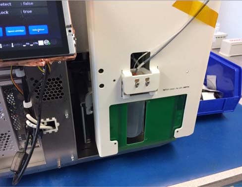
Click to zoom
Application Details
- Equipment Class
- DXX - Part 15 Low Power Communication Device Transmitter
- Date of Grant
- Mar 12, 2015
- Application Purpose
- Original Equipment
- Date of Application
- Mar 12, 2015
- Equipment Note
- 13.56 MHz RFID Reader
- Frequency Range
- 13.56000000 - 13.56000000
- Company
- Thermo Fisher Scientific Inc
- Country
- United States
Documents & Files
Document Text
Text extracted from the exhibit documents filed with the FCC. Open a document above to read the original.
Users Manual
RFID Module Regulatory Information Pub. No. MAN0014027 Rev. A.0 RFID Module This RFID module utilizes near field communication technology. It operates at 13.56 MHz. It is based on the NXP CLRC663 chipset. The RFID module is powered and controlled by USB from the host system. In our DNA sequencing instrument, this RFID module only communicates with our consumable RFID tags during the initialization of each genetic sequencing run while the instrument's door is closed. Once the correct reagents are detected and tags recorded this module will remain in the idle mode until the next sequencing run in several hours. There are no user serviceable parts on this module. The module can only be serviced by Thermo Fisher Scientific personnel. The antenna for this module is fixed and cannot be modified. Note: On the sequencing instrument, RFID regulatory information can be found on the touchscreen under Options4Regulatory info. Regulatory information FCC Notice (for U.S. Customers): This device complies with Part 15 of the FCC Rules: Operation is subject to the following conditions: 1.This device may not cause harmful interference, and 2. This device must accept any interference received, including interference that may cause undesired operation. Changes and Modifications not expressly approved by Thermo Fisher Scientific can void your authority to operate this equipment under Federal Communications Commissions rules. Canada: This device complies with Industry Canada licence-exempt RSS standard(s). Operation is subject to the following two conditions: (1) this device may not cause interference, and (2) this device must accept any interference, including interference that may cause undesired operation of the device. Le present appareil est conforme aux CNR d'Industrie Canada applicables aux appareils radio exempts de licence. L'exploitation est autorisee aux deux conditions suivantes : (1) l'appareil ne doit pas produire de brouillage, et (2) l'utilisateur de l'appareil doit accepter tout brouillage radioelectrique subi, meme si le brouillage est susceptible d'en compromettre le fonctionnement. Limited product warranty Life Technologies Corporation and/or its affiliate(s) warrant their products as set forth in the Life Technologies' General Terms and Conditions of Sale found on Life Technologies' website at www.lifetechnologies.com/termsandconditions. If you have any questions, please contact Life Technologies at www.lifetechnologies.com/support. PRODUCT INFORMATION SHEET For Research Use Only. Not for use in diagnostic procedures. The information in this guide is subject to change without notice. DISCLAIMER TO THE EXTENT ALLOWED BY LAW, LIFE TECHNOLOGIES AND/OR ITS AFFILIATE(S) WILL NOT BE LIABLE FOR SPECIAL, INCIDENTAL, INDIRECT, PUNITIVE, MULTIPLE, OR CONSEQUENTIAL DAMAGES IN CONNECTION WITH OR ARISING FROM THIS DOCUMENT, INCLUDING YOUR USE OF IT. ©2015 Thermo Fisher Scientific Inc. All rights reserved. All trademarks are the property of Thermo Fisher Scientific and its subsidiaries unless otherwise specified. For support visit thermofisher.com/techresources or email [email protected] lifetechnologies.com 4 June 2015
External Photos
External photos: FCC ID: 2AD9Z-INS1011976 and IC: 12763A-INS1011976
Internal Photos
Internal photos: FCC ID: 2AD9Z-INS1011976 and IC: 12763A-INS1011976 Front Rear Transmitter Close Up
Test Report
Compliance Worldwide, Inc. - 357 Main Street - Sandown, NH 03873 (603) 887 3903 Fax 887 6445 http://www.complianceworldwide.com COMPLIANCE WORLDWIDE INC. TEST REPORT 485-14 In Accordance with the Requirements of Federal Communications Commission CFR Title 47 Part 15.225, Subpart C Industry Canada RSS 210, Issue 8, Annex 2 Low Power License-Exempt Radio Communication Devices Intentional Radiators Issued to Thermo Fischer Scientific, Inc. Life Sciences Division 246 Good Lane, Suite 100 Guildford, CT 06437 for the ION Torrent 13.56 MHz RFID Reader Module FCC ID: 2AD9Z-INS1011976 IC: 12763A- INS1011976 Report Issued on March 4, 2015 Tested by This test report shall not be reproduced, except in full, without written permission from Compliance Worldwide, Inc. Test Number: 485-14 Issue Date: 03/04/2015 Page 2 of 18 Compliance Worldwide, Inc. - 357 Main Street - Sandown, NH 03873 (603) 887 3903 Fax 887 6445 http://www.cw-inc.com Table of Contents 1 Scope................................................................................................................................................... 3 2 Product Details .................................................................................................................................... 3 2.1. Manufacturer ............................................................................................................................. 3 2.2. Model Number........................................................................................................................... 3 2.3. Serial Number ........................................................................................................................... 3 2.4. Description ................................................................................................................................ 3 2.5. Power Source............................................................................................................................ 3 2.6. Hardware Revision.................................................................................................................... 3 2.7. Software Revision ..................................................................................................................... 3 2.8. EMC Modifications .................................................................................................................... 3 3. Product Configuration ......................................................................................................................... 3 3.1. Operational Characteristics & Software ....................................................................................3 3.2. EUT Hardware .......................................................................................................................... 3 3.3. EUT Connected Hardware ........................................................................................................ 3 3.4. EUT Cables/Transducers.......................................................................................................... 3 3.5. Support Equipment ................................................................................................................... 3 3.6. Block Diagram........................................................................................................................... 4 4. Measurements Parameters ................................................................................................................ 4 4.1. Measurement Equipment Used to Perform Test ...................................................................... 4 4.2. Measurement & Equipment Setup ............................................................................................ 4 4.3. Measurement Procedure .......................................................................................................... 5 5. Choice of Equipment for Test Suits .................................................................................................... 5 5.1. Choice of Model ........................................................................................................................ 5 5.2. Presentation .............................................................................................................................. 5 5.3. Choice of Operating Frequencies ............................................................................................. 5 6. Measurement Summary ..................................................................................................................... 6 7. Measurement Data ............................................................................................................................. 6 7.1. Antenna Requirement ............................................................................................................... 6 7.2. Operation within the Band 13.110 MHz – 14.010 MHz (Field Strength)................................... 7 7.3. Operation within the Band 13.110 MHz – 14.010 MHz (Frequency Tolerance) ....................... 8 7.4. Transmitter Spurious Radiated Emissions................................................................................ 9 7.4. Transmitter Spurious Radiated Emissions (Harmonic Emissions) ......................................... 20 7.5. Power Line Conducted Emissions .......................................................................................... 21 7.6. Occupied Bandwidth ............................................................................................................... 24 7.7. 99% Power Bandwidth ............................................................................................................ 25 8. Test Site Description ........................................................................................................................ 26 Test Number: 485-14 Issue Date: 03/04/2015 Page 3 of 18 Compliance Worldwide, …
Text truncated - open the document above for the full version.
Test Setup Photos
Test Set up photos: FCC ID: 2AD9Z-INS1011976 and IC: 12763A-INS1011976 Frequency Tolerance Frequency Tolerance Radiated Bilog Front Radiated Bilog Rear Loop Conducted Emissions
Contact Information
Applicant
Scott Taylor(Staff Engineer)
Test Firm
Compliance Worldwide, Inc.Deb Bourbeau
Technical Specifications
| # | Rule Parts | Frequency Range | Power Output |
|---|---|---|---|
| 1 | 15C | 13.56 MHz - 13.56 MHz | - |