2ADAKSFFR615WUH1Small Form Factor Repeater
Etherstack Inc.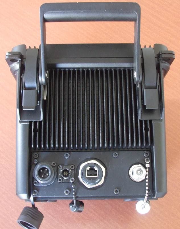
Click to zoom
Application Details
- Equipment Class
- TNB - Licensed Non-Broadcast Station Transmitter
- Date of Grant
- Mar 05, 2015
- Application Purpose
- Original Equipment
- Date of Application
- Mar 05, 2015
- Equipment Note
- Small Form Factor Repeater
- Frequency Range
- 440.00000000 - 512.00000000
- Company
- Etherstack Inc.
- Country
- United States
Documents & Files
Document Text
Text extracted from the exhibit documents filed with the FCC. Open a document above to read the original.
Users Manual
SFFR-6 User Manual SFFR-6 USER MANUAL Version 2.04a | February 2015 Small Form Factor Tactical Repeater and Base Station SFFR-6 User Manual Contents Doc ID: ES1002-UM02-v204a Copyright © 2014 Etherstack London Limited Page ii 1 Introduction ................................................................................................................. 6 1.1 Overview ..................................................................................................................................................................... 7 1.2 Document Conventions............................................................................................................................................... 7 1.3 Features ...................................................................................................................................................................... 8 1.4 Technical Specifications ............................................................................................................................................ 10 2 Getting Started .......................................................................................................... 11 2.1 Package Contents ...................................................................................................................................................... 12 2.2 Getting to know your GoBox ..................................................................................................................................... 13 2.2.1 Locking Clamps ................................................................................................................................................... 13 2.2.2 Lid ....................................................................................................................................................................... 13 2.2.3 Interface Module ................................................................................................................................................ 14 2.2.4 Battery Compartment ........................................................................................................................................ 15 2.2.5 Control Module .................................................................................................................................................. 15 2.2.5.1 Ethernet (Programming Port) ......................................................................................................................... 15 2.2.5.2 Accessory Connector ...................................................................................................................................... 15 2.2.5.3 Status Window ............................................................................................................................................... 16 2.2.5.4 Backlight Button ............................................................................................................................................. 16 2.2.5.5 Power Button ................................................................................................................................................. 16 2.2.5.6 Rotary Dial and Button ................................................................................................................................... 16 2.2.5.7 Tx and RX LED ................................................................................................................................................. 16 2.2.5.8 Power LED ...................................................................................................................................................... 16 2.2.6 Radio Module ..................................................................................................................................................... 16 2.2.7 Duplexer ............................................................................................................................................................. 17 2.2.8 Power Amplifier.................................................................................................................................................. 17 3 Configuration ............................................................................................................. 18 3.1 Before you begin ....................................................................................................................................................... 19 3.1.1 About GoBox Configuration Files ....................................................................................................................... 19 3.1.2 About Operational Profiles ................................................................................................................................. 19 3.1.3 About Duplexer Group Tags ............................................................................................................................... 19 3.1.4 What you need to program and test your GoBox .............................................................................................. 20 3.1.4.1 Laptop or PC with an Ethernet Interface ........................................................................................................ 20 3.1.4.2 Radios ............................................................................................................................................................. 20 3.2 Connecting to your GoBox configuration interface .................................................................................................. 21 3.3 Managing Operational Profiles ................................................................................................................................. 22 3.3.1 Adding a P25 Conventional Repeating Profile .............................................................................................…
Text truncated - open the document above for the full version.
Attestation Statements
Etherstack Inc | New York (GMT -5) 1115 Broadway, Suite #1276 New York, NY 10010 UNITED STATES E: [email protected] P: +1 917 661 4110 Sydney (GMT +10) P: +61 2 8399 7500 [email protected] Yokohama (GMT +9) P: +81 45 342 9050 [email protected] London (GMT) P: +44 207 734 0200 [email protected] Date: 2 nd March 2015 Federal Communications Commission Equipment Authorization Branch 7435 Oakland Mills Road Columbia, MD 21046 United States of America. To whom it may concern: ATTESTATION STATEMENT - FCC ID: 2ADAKSFFR615WUH1 As per 47CFR Section 90.203(j)(5), Etherstack Inc hereby affirm the above model is capable of the spectrum efficiency standard of one voice channel per 6.25kHz of channel bandwidth. The model is capable via 2 digitized 3600 bps voice channels over a single 9600 bps digital modulation within 12.5kHz of channel bandwidth. Additionally, Etherstack Inc, affirm the equipment is capable of supporting a minimum data rate of 4800 bits per second per 6.25 kHz of channel bandwidth. The model is capable via 9600 bps digital modulation within 12.5kHz of channel bandwidth. Please contact me if you require any additional information. Yours faithfully, Doug J Chapman, Vice President Business Development Etherstack Inc.
Cover Letter(s)
Etherstack Inc | New York (GMT -5) 1115 Broadway, Suite #1276 New York, NY 10010 UNITED STATES E: [email protected] P: +1 917 661 4110 Sydney (GMT +10) P: +61 2 8399 7500 [email protected] Yokohama (GMT +9) P: +81 45 342 9050 [email protected] London (GMT) P: +44 207 734 0200 [email protected] Date: 17 th February 2015 Federal Communications Commission Equipment Authorisation Branch 7435 Oakland Mills Road Columbia, MD 21046 United States of America. To whom it may concern: CONFIDENTIALITY REQUEST - FCC ID: 2ADAKSFFR615WUH1 With reference to FCC 47 CFR Section 0.457 (d) (ii) and pursuant to rule Section 0.459, long-term confidentiality is requested as follows. Specific Information: Schematics, Block Diagrams, Parts Lists, Tune-Up Procedure and Theory of Operation/Operational Description. Etherstack considers that all the above specific information contains trade secrets which are not made routinely available to the public or to our competitors. Disclosure of this information could result in an unfair advantage to our competitors. It should be treated as confidential for the duration of the Grant of Authorisation. Please contact me if you require any additional information. Yours faithfully, Doug J Chapman, Vice President Business Development Etherstack Inc.
Cover Letter(s)
Etherstack Inc | New York (GMT -5) 1115 Broadway, Suite #1276 New York, NY 10010 UNITED STATES E: [email protected] P: +1 917 661 4110 Sydney (GMT +10) P: +61 2 8399 7500 [email protected] Yokohama (GMT +9) P: +81 45 342 9050 [email protected] London (GMT) P: +44 207 734 0200 [email protected] 17 th February, 2015. Timco Engineering, Inc. 849 NW State Road 45 P.O. Box 370 Newberry, Florida 32669. FCC ID: 2ADAKSFFR615WUH1 Subject: Etherstack Inc. justification letter for expanded frequency range 440 - 479 MHz Gentlemen, You have asked Etherstack Inc. for justification to have the 440-479 MHz frequency range appear on the face of the FCC Grant of Certification for a Part 90 Certification. (1) This radio repeater is used in systems by Federal and Public Safety agencies including Police, Fire, and Emergency Medical Services, etc. (2) This frequency range is regarded as usual and customary by the United States Federal Government and its various departments, user organizations and the military to appear on the face of the equipment Grant of Certification. (3) Etherstack Inc. Marketing Department plans to ensure that USA users, other than those specifically identified in this letter, do not operate within the bands of 440-479 MHz, as controlled by the users’ FCC station license. (4) This device will not be marketed to USA users, other than those identified in the letter, namely the US Government and its various departments, user organizations and the military, for operation in 440-479 MHz frequency range. (5) Equipment programming is the responsibility of Authorized Service Personnel. (6) The radio repeater complies with 47 CFR Part 90.203(e), in that the operator cannot directly program the transmit frequencies using the normally accessible external controls. (7) As per FCC KDB634817 guidance, “as an alternative to listing the exact frequencies, we acknowledge that it’s a violation of the FCC Rules if this device operates on unauthorized frequencies. Yours faithfully, Doug J Chapman, Vice President Business Development Etherstack Inc.
External Photos
____________________________________________________________________________________________________________________________________________________________________________ Page 19 of 21 Test Report No 141017.1 3 rd December 2014. This report may not be reproduced except in full. 9. PHOTOGRAPHS
ID Label/Location Info
16/02/15 dd/mm/yy v100 Revisions: Changes madeREV Brand label position FCC / IC Identification label position Model / Serial Number label position i n d u s t r i a l d e s i g n tel (direct) 02 9337 6266 171 Hopetoun Avenue Watsons Bay NSW 2030 Australia tel + 61 2 9337 6255 mob 0411 114369 fax 02 9337 6355 www.cube.net.au [email protected] File Name: ES1002-MA11_v100_Location_FCC_ID_Label Drawing Number: ES1001-MA11 Scale: Not to Scale Sheet size A4 Drawn by: Graeme MacDonald Title: Location of FCC / IC Identification Label Date R 3.00 Typ Title: SFFR615WUH1 FCC ID Label 49.00 24.00 Label Dimensions File Name: ES1002- MP48_v1 00_FCC_ID Base Material: Aluminium 0.25mm thick nom. Adhesi ve : 3M 468MP, 0.13 thick nom. Drawn by: Graeme MacDonald Sca le 1:1 Sheet si ze A4 Colour: Natural (si lve r) i n d u s t r i a l d e s i g n tel (direct) 02 9337 6266 171 Hopetoun Avenue Watsons Bay NSW 2030 Australia tel + 61 2 9337 6255 mob 0411 114369 fax 02 9337 6355 www.cube.net.au [email protected] Print: Black (text is silve r in black ground) Part Number: ES1002- MP48 Date 16/02/15 dd /mm/yy v1 00 Revi si ons: Changes made REV
Internal Photos
IGEP PCB Assembly Main Chassis Backplane PCB Assembly PB02 Power Amplifier PCB Assembly PB03 Duplexer PCB Assembly PB04 Transceiver Carrier PCB Assembly PB06 Controller Display PCB Assembly PB07 DC Power Management PCB Assembly PB08 AC-DC PCB Assembly PB09 UHF Filter PCB Assembly XR25 Transceiver PCB Assembly
RF Exposure Info
____________________________________________________________________________________________________________________________________________________________________________ Page 17 of 21 Test Report No 141017.1 3 rd December 2014. This report may not be reproduced except in full. Exposure of humans to RF fields As per FCC KDB 447498 D01 and Section 2.1091 radio frequency transmitters are required to be operated in a manner that ensures the public is not exposed to RF energy levels. Calculations have been made using the General Public/Uncontrolled Exposure limits that are defined in Section 1.1310. Minimum safe distances have been calculated below. Power density, mW/cm 2 = E 2 /3770 - General Population / Uncontrolled exposure limit will be 0.29 mW/cm 2 (f/1500 = 440 MHz/1500) As this radio can operate over the range of 440 - 512 MHz the lowest frequency of operation in the USA, which will give the worst case result, would be 440 MHz. The minimum distance from the antenna at which the MPE is met is calculated from the equation relating field strength in V/m, transmit power in watts, transmit antenna gain, transmitter duty cycle and separation distance in metres: Power Density = 0.29 mW/cm 2 = E 2 /3770 E= √0.29*3770 E = 33.1 V/m The rated maximum transmitter power (P) = 15 watts (+40 dBm). A duty cycle (DC) of 100% as the transmitter is a base station could possibly be operated for long periods of time. Transmitter is operated using a quarter wave whip antenna with a gain (G) of 2.14 dBi (1.64). The safe distance would be calculated as follows: d = √ (30 * P * G*DC) / E d = √ (30 * 15 * 1.64 * 1.0) / 33.1 d = 0.82 metres or 82 cm Result: Complies if the safe distances defined above are applied.
Test Report
____________________________________________________________________________________________________________________________________________________________________________ Page 1 of 22 Test Report No 141017.1 6th March 2015. This report may not be reproduced except in full. EMC Technologies (NZ) Ltd PO Box 68-307, Newton Auckland New Zealand Phone 09 360 0862 Fax 09 360 0861 E-Mail Address: [email protected] Web Site: www.emctech.com.au TEST REPORT Etherstack Inc. SFFR615WUH1 UHF Small Form Factor Repeater tested to the Code of Federal Regulations (CFR) 47 Part 90 –Private Land Mobile Services for Etherstack Inc. This Test Report is issued with the authority of: _______________________________ Andrew Cutler - General Manager ____________________________________________________________________________________________________________________________________________________________________________ Page 2 of 22 Test Report No 141017.1 6th March 2015. This report may not be reproduced except in full. Table of Contents 1. COMPLIANCE STATEMENT 3 2. RESULT SUMMARY 3 3. ATTESTATION 4 4. CLIENT INFORMATION 5 5. TEST SAMPLE DESCRIPTION 5 6. TEST RESULTS 7 7. TEST EQUIPMENT USED 19 8. ACCREDITATIONS 19 9. PHOTOGRAPHS 20 ____________________________________________________________________________________________________________________________________________________________________________ Page 3 of 22 Test Report No 141017.1 6th March 2015. This report may not be reproduced except in full. 1. COMPLIANCE STATEMENT The Etherstack Inc. SFFR615WUH1 UHF Small Form Factor Repeater complies with the limits defined in 47 CFR Part 90 and 47 CFR Part 2 when tested in-accordance with the test methods described in 47 CFR Part 2 and ANSI/ TIA-603-C. 2. RESULT SUMMARY The results of testing, carried out between 12 th and the 25 th November 2014, are summarised below. Clause Description Result 90.203 Certification required Noted 2.1046 90.205 RF power output Power and antenna height limits Noted Complies 2.1049 2.202 90.207 90.209 90.210 Occupied bandwidth Bandwidths Types of emissions Bandwidth limitations Emission masks Noted Noted Complies Complies Complies 2.1051 Spurious emissions at antenna terminals Complies 2.1053 Field strength of spurious radiation Complies 2.1055 90.213 Frequency stability Frequency stability Noted Complies 90.214 Transient frequency behaviour Complies 1.1310 Radio frequency exposure limits Complies ____________________________________________________________________________________________________________________________________________________________________________ Page 4 of 22 Test Report No 141017.1 6th March 2015. This report may not be reproduced except in full. 3. ATTESTATION This report describes the tests and measurements performed for the purpose of determining compliance with the specification with the following conditions: The client selected the test sample. The report relates only to the sample tested. This report does not contain corrections or erasures. Measurement uncertainties with statistical confidence intervals of 95% are shown below test results. Both Class A and Class B uncertainties have been accounted for, as well as influence uncertainties where appropriate. In addition this equipment has been tested in accordance with the requirements contained in the appropriate Commission regulations. All compliance statements have been made with respect of the specification limit with no reference to the measurement uncertainty. To the best of my knowledge, these tests were performed using measurement procedures that are consistent with industry or Commission standards and demonstrate that the equipment complies with the appropriate standards. I further certify that the necessary measurements were made by EMC Technologies NZ Ltd, 47 MacKelvie Street, Grey Lynn, Auckland, New Zealand. Andrew Cutler General Manager EMC Technologies NZ Ltd ____________________________________________________________________________________________________________________________________________________________________________ Page 5 of 22 Test Report No 141017.1 6th March 2015. This report may not be reproduced except in full. 4. CLIENT INFORMATION Company Name Etherstack Inc. Address 1115 Broadway, Suite 1276, New York, NY10010 Country United States of America Contact Mr Doug Chapman 5. TEST SAMPLE DESCRIPTION Brand Name Etherstack Inc. Model Number SFFR615WUH1 Product UHF Small Form Factor Repeater Manufacturer Etherstack London Ltd Country of Origin Australia Serial Number 1200018 FCC I.D 2ADAKSFFR615WUH1 Product overview The SFFR615WUH1 is a small form factor portable repeater that is self-powered and can operate as an APCO P25 standalone repeater. Power Supply: DC Supply 12 Vdc 10.8 – 15.6 volt dc Max 10 amps AC Supply: 100 - 240 Vdc (47-63 Hz) Internal Batteries 11.25 Vdc Li-ION rechargeable x 2 Output Power 1 W (+30.0 dBm) to 15 watts (+41.8 dBm) ____________________________________________________________________________________________________________________________________________________________________________ Page 6 of 22 Test Report No 141017.1 6th March 2015. This report may not be reproduced except in full. Transmitter FCC Frequency Bands Part 90: 440 - 512 MHz Test frequency Emission Designators 8K10F1D 8K10F1E 8K10F7D 8K10F7E 8K10F1W 8K10F7W Standard Temperature and Humidity Temperature: +15 C to + 30 C maintained. Relative Humidity: 20% to 75% observed. Standard Test Power Source Standard Test Voltage: 13.8 Vdc Extreme Temperature High Temperature: + 50 C maintained. Low Temperature: - 30 C maintained. Extreme Test Voltages Low Voltage: 10.8 Vdc High Voltage: 15.6 Vdc Frequency (MHz) Power (Watts) Spacing (kHz) 487.7250 15.0 12.5 ____________________________________________________________________________________________________________________________________________________________________________ Page 7 of 22 Test Report No 141017.1 6th March 2015. This re…
Text truncated - open the document above for the full version.
Test Setup Photos
____________________________________________________________________________________________________________________________________________________________________________ Page 20 of 21 Test Report No 141017.1 3 rd December 2014. This report may not be reproduced except in full. Radiated emissions setup ____________________________________________________________________________________________________________________________________________________________________________ Page 21 of 21 Test Report No 141017.1 3 rd December 2014. This report may not be reproduced except in full.
Contact Information
Applicant
Douglas Chapman(V.P. Business Development)
Test Firm
EMC Technologies NZ Ltd.Andrew Cutler
Technical Specifications
| # | Rule Parts | Frequency Range | Power Output | Emission | Tolerance |
|---|---|---|---|---|---|
| 6 | 9 | 440 MHz - 512 MHz | 15 W | 8K10F1W | 1 ppm |