2ADAL-VA7401Vector Stadium Receiver
Catapult Sports Pty Ltd
Click to zoom
Application Details
- Equipment Class
- UWB - Ultra Wideband Transmitter
- Date of Grant
- Aug 25, 2020
- Application Purpose
- Original Equipment
- Date of Application
- Aug 24, 2020
- Equipment Note
- Vector Stadium Receiver
- Frequency Range
- 3638.10000000 - 4374.80000000
- Company
- Catapult Sports Pty Ltd
- Country
- United States
Documents & Files
Document Text
Text extracted from the exhibit documents filed with the FCC. Open a document above to read the original.
Users Manual
1 Catapult Vector User Manual Contents 1. OUTLINE ...................................................................................................................Pg. 2 2. VECTOR S7 DEVICE ................................................................................................ Pg. 2 - 4 3. SYSTEM LOGIN ........................................................................................................Pg. 4 - 5 4. COLLECTING DATA ..................................................................................................Pg. 6 - 7 5. DOWNLOADING DATA ..........................................................................................Pg. 7 - 8 6. SOFTWARE USER GUIDE LINKS ............................................................................. Pg. 8 7. VECTOR ANCHOR & VECTOR DOCK ..................................................................... Pg. 9 - 10 8. SUPPORT & HELP ................................................................................................... Pg. 10 9. REGULATORY NOTICES ......................................................................................... Pg. 10 - 11 2 1. OUTLINE The Catapult Vector S7device is a professional-grade GNSS system designed to measure the performance of elite athletes within individual and team sports. This document introduces the Vector S7 hardware components and provides an explanation of functionality and general operation. The OpenField software system Data is collected live and downloaded to the OpenField console and can then be uploaded to the OpenField cloud post session. To store the collected data on the OpenField cloud, data must be synced from the console to the cloud over a solid internet connection. Users have the option to use the OpenField+ mobile/iPad app to view live data through a mobile or an iPad over a local Catapult Wi-Fi. This improves accessibility as it enables users to be more mobile around the pitch and to share live data more easily with coaches and players. The hardware components of the Vector system include the Vector devices, a wireless UWB receiver(s) for GPS/GNSS and RTLS tracking. 2. VECTOR S7 DEVICE The Vector S7 is a wearable (combined) GNSS / LPS device with embedded microsensors that is used to measure the performance of elite athletes, in both real-time and post session. The Vector S7 device contains the following measurement sensors and components: GNSS module (10Hz GNSS / 18Hz GPS) GNSS antenna RTLS antenna Tri-axial Accelerometer (up to 1000 Hz) Tri-axial Gyroscope (up to 1000 Hz) Tri-axial Magnetometer (up to 1000Hz) Magnetic Heart Rate Receiver ECG heart rate board (up to 250Hz) Bluetooth Low Energy Device status LED’s Haptic feedback via vibration unit UWB Antenna All sensors are sampling continuously, and data is logged onto an onboard SD card as well as transmitted live via ultra-wide-band (UWB) or Bluetooth (BLE). 3 Figure 1. – Vector S7 wearable Device DEVICE ICON/LED FUNCTIONALITY A: Indicates the state of the battery (charging, low battery, ect) B: Indicates a connection to the sateliete (GNSS) or ClearSky RTLS system. C: Indicates a connection to Heart Rate D: Indicates use of ultra-wide band. E: Indicates a connection to Bluetooth. Vector S7 Device Operation Overview: 1. Charging: Each Vector S7 device is charged and configured, prior to use, using the specifically designed Vector Dock. This is a 24-device tray that connects to mains supply mains supply for the purpose of Vector S7 charging. 2. Configuration: Configuration of the Vector S7 occurs via USB serial connection from the dock to the desktop software (OpenField) where athlete and device settings are transferred and stored on the Vector S7 device. This process occurs automatically as the devices are recognized by the system and as each device is assigned to an athlete. 3. Assigning Athletes to Devices: after logging in and pressing start, navigating to the settings menu will show athletes. Pressing ‘auto-assign’ will assign device ID’s to players and will then transfer this configuration to the devices as described above 4. Starting a live session: Connect the Vector Anchor via USB. In the software from the main screen, press the ‘quick start’ icon to start a live session. Vector S7 devices will show in ‘active players’ once they obtain GNSS lock and data transmission will begin. You can check if data is incoming by checking the orange and black bar in the top right corner of the interface. Press ‘All’ in active 4 players box then press ‘+period’ to start recording. To end the live session, press the stop icon 5. Download Session: Turn the devices off by pressing the button on the side of the device for 2 seconds and release. Place Vector S7 devices in Vector Dock press the dock ‘ignition button’ and connect USB to PC. Press settings then transfer. Press begin transfer. Once display says ‘finished’, data can be viewed from calendar. DEVICE CONNECTORS & FEATURES Top Charging LED: Located on the top of the device is a LED used to indicate the charging and enumeration state of the device. Power Button: The power button has been placed on the edge of the device to make the device harder to press during play and thus minimizing accidental device turn offs. HR pins: Allows the user to clip the device into a vest to collect HR data using an intergrated heart rate vest. Charging Pins: Allows the device to connect to the Vector Dock which enables the device(s) to charge and connect / data transfer to the PC. FIRST USE AND CHARGE Ensure the devices are fully charged before using them to collect data for a session. To charge the devices, connect the Vector Dock to a power supply and then place the devices into an individual dock slot on the Vector charging dock. The top LED charging light will flash when the device is charging. The top battery LED turns solid green when the device is fully charged. To turn the device on, press the button on the side of the device or set a…
Text truncated - open the document above for the full version.
Attestation Statements
Supplier's Declaration of Conformity 47 CFR § 2.1077 Compliance Information Unique Identifier VA7401 Responsible Party Catapult Sports Pty. Ltd 181 Ballardvale Street Wilmington Massachusetts 01887 United States of America E-mail: [email protected] FCC Compliance Statement This device complies with Part 15 of the FCC Rules. Operation is subject to the following two conditions: (1) This device may not cause harmful interference, and (2) this device must accept any interference received, including interference that may cause undesired operation.
External Photos
PHOTOS - EXTERNAL Company: Catapult Sports Product Name: Vector Stadium Receiver Report No.: CATA03 – External Photos Title: CATA03 – External Photos To: Serial #: Issue Date: 09 June 2020 Page: 2 of 9 This test report may be reproduced in full only. The document may only be updated by MiCOM Labs personnel. All changes will be noted in the Document History section of the report. MiCOM Labs, 575 Boulder Court, Pleasanton, California 94566 USA, Phone: +1 (925) 462 0304, Fax: +1 (925) 462 0306, www.micomlabs.com 1. External Photographs 1.1.1. Product - External CATA03 Back Title: CATA03 – External Photos To: Serial #: Issue Date: 09 June 2020 Page: 3 of 9 This test report may be reproduced in full only. The document may only be updated by MiCOM Labs personnel. All changes will be noted in the Document History section of the report. MiCOM Labs, 575 Boulder Court, Pleasanton, California 94566 USA, Phone: +1 (925) 462 0304, Fax: +1 (925) 462 0306, www.micomlabs.com CATA03 Front Top Title: CATA03 – External Photos To: Serial #: Issue Date: 09 June 2020 Page: 4 of 9 This test report may be reproduced in full only. The document may only be updated by MiCOM Labs personnel. All changes will be noted in the Document History section of the report. MiCOM Labs, 575 Boulder Court, Pleasanton, California 94566 USA, Phone: +1 (925) 462 0304, Fax: +1 (925) 462 0306, www.micomlabs.com CATA03 Left Side Title: CATA03 – External Photos To: Serial #: Issue Date: 09 June 2020 Page: 5 of 9 This test report may be reproduced in full only. The document may only be updated by MiCOM Labs personnel. All changes will be noted in the Document History section of the report. MiCOM Labs, 575 Boulder Court, Pleasanton, California 94566 USA, Phone: +1 (925) 462 0304, Fax: +1 (925) 462 0306, www.micomlabs.com CATA03 Ports Title: CATA03 – External Photos To: Serial #: Issue Date: 09 June 2020 Page: 6 of 9 This test report may be reproduced in full only. The document may only be updated by MiCOM Labs personnel. All changes will be noted in the Document History section of the report. MiCOM Labs, 575 Boulder Court, Pleasanton, California 94566 USA, Phone: +1 (925) 462 0304, Fax: +1 (925) 462 0306, www.micomlabs.com CATA03 Right Side Title: CATA03 – External Photos To: Serial #: Issue Date: 09 June 2020 Page: 7 of 9 This test report may be reproduced in full only. The document may only be updated by MiCOM Labs personnel. All changes will be noted in the Document History section of the report. MiCOM Labs, 575 Boulder Court, Pleasanton, California 94566 USA, Phone: +1 (925) 462 0304, Fax: +1 (925) 462 0306, www.micomlabs.com CATA03 Top Side Title: CATA03 – External Photos To: Serial #: Issue Date: 09 June 2020 Page: 8 of 9 This test report may be reproduced in full only. The document may only be updated by MiCOM Labs personnel. All changes will be noted in the Document History section of the report. MiCOM Labs, 575 Boulder Court, Pleasanton, California 94566 USA, Phone: +1 (925) 462 0304, Fax: +1 (925) 462 0306, www.micomlabs.com EUT opened 575 Boulder Court Pleasanton, California 94566, USA Tel: +1 (925) 462 0304 Fax: +1 (925) 462 0306 www.micomlabs.com
Internal Photos
PHOTOS - INTERNAL Company: Catapult Sports Product Name: Vector Stadium Receiver Report No.: CATA03 – Internal Photos Title: CATA03 Internal Photos To: Serial #: Issue Date: 15 June 2020 Page: 2 of 7 This test report may be reproduced in full only. The document may only be updated by MiCOM Labs personnel. All changes will be noted in the Document History section of the report. MiCOM Labs, 575 Boulder Court, Pleasanton, California 94566 USA, Phone: +1 (925) 462 0304, Fax: +1 (925) 462 0306, www.micomlabs.com 1. Internal Photographs 1.1.1. Product - Internal IO Board Bottom Title: CATA03 Internal Photos To: Serial #: Issue Date: 15 June 2020 Page: 3 of 7 This test report may be reproduced in full only. The document may only be updated by MiCOM Labs personnel. All changes will be noted in the Document History section of the report. MiCOM Labs, 575 Boulder Court, Pleasanton, California 94566 USA, Phone: +1 (925) 462 0304, Fax: +1 (925) 462 0306, www.micomlabs.com IO Board Top Main Board Bottom Title: CATA03 Internal Photos To: Serial #: Issue Date: 15 June 2020 Page: 4 of 7 This test report may be reproduced in full only. The document may only be updated by MiCOM Labs personnel. All changes will be noted in the Document History section of the report. MiCOM Labs, 575 Boulder Court, Pleasanton, California 94566 USA, Phone: +1 (925) 462 0304, Fax: +1 (925) 462 0306, www.micomlabs.com Main Board RF Module Removed Main Board Top Title: CATA03 Internal Photos To: Serial #: Issue Date: 15 June 2020 Page: 5 of 7 This test report may be reproduced in full only. The document may only be updated by MiCOM Labs personnel. All changes will be noted in the Document History section of the report. MiCOM Labs, 575 Boulder Court, Pleasanton, California 94566 USA, Phone: +1 (925) 462 0304, Fax: +1 (925) 462 0306, www.micomlabs.com Main Board Top Shield off Main Board Top Shields on Title: CATA03 Internal Photos To: Serial #: Issue Date: 15 June 2020 Page: 6 of 7 This test report may be reproduced in full only. The document may only be updated by MiCOM Labs personnel. All changes will be noted in the Document History section of the report. MiCOM Labs, 575 Boulder Court, Pleasanton, California 94566 USA, Phone: +1 (925) 462 0304, Fax: +1 (925) 462 0306, www.micomlabs.com RF Module Bottom RF Module Top 575 Boulder Court Pleasanton, California 94566, USA Tel: +1 (925) 462 0304 Fax: +1 (925) 462 0306 www.micomlabs.com
RF Exposure Info
MPE/RF EXPOSURE TEST REPORT FCC CFR 47 Part 1.1310 Report No.: CATA03_FCC_MPE Rev A Company: Catapult Sports Pty Ltd Model Name: VA7401 MPE/RF EXPOSURE TEST REPORT Company: Catapult Sports Pty Ltd Model Name: VA7401 To: FCC CFR 47 Part 1.1310 Test Report Serial No.: CATA03_FCC_MPE Rev A This report supersedes: NONE Applicant: Catapult Sports Pty Ltd Company 75-83 High St Prahran Melbourne, Victoria 3181 Australia Issue Date: 11 th June 2020 This Test Report is Issued Under the Authority of: MiCOM Labs, Inc. 575 Boulder Court Pleasanton California 94566 USA Phone: +1 (925) 462-0304 Fax: +1 (925) 462-0306 www.micomlabs.com MiCOM Labs is an ISO 17025 Accredited Testing Laboratory Title: Catapult Sports Pty Ltd Company To: FCC CFR 47 Part 1.1310 Serial #: CATA03_FCC_MPE Rev A Issue Date: 11 th June 2020 Page: 3 of 4 This test report may be reproduced in full only. The document may only be updated by MiCOM Labs personnel. All changes will be noted in the Document History section of the report. MiCOM Labs, 575 Boulder Court, Pleasanton, California 94566 USA, Phone: +1 (925) 462 0304, Fax: +1 (925) 462 0306, www.micomlabs.com 1. MAXIMUM PERMISSABLE EXPOSURE Calculations for Maximum Permissible Exposure Levels Power Density = Pd (mW/cm 2 ) = EIRP/(4*π*d 2 ) EIRP = P * G P = Peak output power (mW) G = Antenna numeric gain (numeric) d = Separation distance (cm) Numeric Gain = 10 ^ (G (dBi)/10) The calculations in the table below use the highest conducted power values together with the lowest antenna gain specified for the EUT. These calculations represent worst case in terms of the exposure levels. Freq. Band (MHz) Ant Gain (dBi) Numeric Gain (numeric) Peak Output Power (dBm) Peak Output Power (mW) Calculated Power Density (mW/cm 2 ) @ 20cm Power Density Limit (mW/cm 2 ) Min Calculated safe distance for Limit (cm) Calculated Power Density (mW/cm 2 ) @ Safe Distance 2400.0 - 2483.5 (WiFi) 4.0 2.51 19.80 95.50 0.048 1.00 4.37 1.00 5150.0 - 5850.0 (WiFi) 7.0 5.01 11.49 14.09 0.014 1.00 2.37 1.00 2400.0 - 2483.5 (BLE) 2.0 2 1.58 6.90 0.00154 1.00 0.79 1.00 3993.6 (UWB) 2.0 1.58 -8.72 0.13 0.00004 1.00 0.13 1.00 NOTE: for mobile or fixed location transmitters the minimum separation distance is 20cm, even if calculations indicate the MPE distance to be less. NOTE: MPE exemption applies for the VA7401 as the EIRP is <20mW Specification - Maximum Permissible Exposure Limits The Limit is defined in Table 1 of FCC §1.1310. 575 Boulder Court Pleasanton, California 94566, USA Tel: +1 (925) 462 0304 Fax: +1 (925) 462 0306 www.micomlabs.com
Test Report
REGULATORY COMPLIANCE TEST REPORT FCC Part 15 Subpart F 15.519, 15.521 - UWB Device Report No.: CATA03-U10 Rev A Company: Catapult Sports Pty Ltd Model Name: VA7401 REGULATORY COMPLIANCE TEST REPORT Company: Catapult Sports Pty Ltd Model Name: VA7401 To: FCC CFR 47 Part 15 Subpart F 15.519, 15.521 Test Report Serial No.: CATA03-U10 Rev A This report supersedes: NONE Applicant: Catapult Sports Pty Ltd Company 75-83 High St Prahran Melbourne, Victoria 3181 Australia Issue Date: 20th August 2020 This Test Report is Issued Under the Authority of: MiCOM Labs, Inc. 575 Boulder Court Pleasanton California 94566 USA Phone: +1 (925) 462-0304 Fax: +1 (925) 462-0306 www.micomlabs.com MiCOM Labs is an ISO 17025 Accredited Testing Laboratory Title: Catapult Sports Pty Ltd Company VA7401 To: FCC CFR 47 Part 15F, 15.519, 15.521 Serial #: CATA03-U10 Rev A Issue Date: 20th August 2020 Page: 3 of 48 This test report may be reproduced in full only. The document may only be updated by MiCOM Labs personnel. All changes will be noted in the Document History section of the report. MiCOM Labs, 575 Boulder Court, Pleasanton, California 94566 USA, Phone: +1 (925) 462 0304, Fax: +1 (925) 462 0306, www.micomlabs.com Table of Contents 1. ACCREDITATION, LISTINGS & RECOGNITION ................................................................................ 4 1.1. TESTING ACCREDITATION ........................................................................................................ 4 1.2. RECOGNITION ............................................................................................................................. 5 1.3. PRODUCT CERTIFICATION ........................................................................................................ 6 2. DOCUMENT HISTORY ......................................................................................................................... 7 3. TEST RESULT CERTIFICATE ............................................................................................................. 8 4. REFERENCES AND MEASUREMENT UNCERTAINTY ..................................................................... 9 4.1. Normative References .................................................................................................................. 9 4.2. Test and Uncertainty Procedure ................................................................................................. 10 5. PRODUCT DETAILS AND TEST CONFIGURATIONS ..................................................................... 11 5.1. Technical Details ......................................................................................................................... 11 5.2. Scope Of Test Program .............................................................................................................. 12 5.3. Equipment Model(s) and Serial Number(s) ................................................................................. 13 5.4. Antenna Details ........................................................................................................................... 13 5.5. Cabling and I/O Ports .................................................................................................................. 13 5.6. Test Configurations ..................................................................................................................... 13 5.7. Equipment Modifications ............................................................................................................. 13 5.8. Deviations from the Test Standard ............................................................................................. 13 6. TEST SUMMARY ................................................................................................................................ 14 7. TEST EQUIPMENT CONFIGURATION(S) ......................................................................................... 15 7.1. Conducted Test Setup ................................................................................................................ 15 7.2. Radiated Emissions - 3m Chamber ............................................................................................ 16 8. MEASUREMENT AND PRESENTATION OF TEST DATA ............................................................... 19 9. TEST RESULTS .................................................................................................................................. 20 9.1. USB Bandwidth ........................................................................................................................... 20 9.2. Transmit Power ........................................................................................................................... 22 9.3. Peak Power Density .................................................................................................................... 24 9.4. Transmitter Spurious Band Emissions ........................................................................................ 26 9.4.1. Transmitter Spurious Emissions ........................................................................................... 28 9.4.2. GPS Band Emissions ........................................................................................................... 39 9.4. Shutoff Timing Requirements ...................................................................................................... 41 9.5. AC Mains Power Input / Output Ports ......................................................................................... 43 Title: Catapult Sports Pty Ltd Company VA7401 To: FCC CFR 47 Part 15F, 15.519, 15.521 Serial #: CATA03-U10 Rev A Issue Date: 20th August 2020 Page: 4 of 48 This test report may be reproduced in full only. The document may only be updated by MiCOM Labs personnel. All changes will be noted in the Document History section of the report. MiCOM Labs, 575 Boulder Court, Pleasanton, Cal…
Text truncated - open the document above for the full version.
Test Setup Photos
PHOTOS - TEST SETUP Company: Catapult Sports Product Name: Vector Stadium Receiver Report No.: CATA03 – FCC Test Setup Photos Title: CATA03 – FCC Test Setup Photos To: Serial #: Issue Date: 09 June 2020 Page: 2 of 6 This test report may be reproduced in full only. The document may only be updated by MiCOM Labs personnel. All changes will be noted in the Document History section of the report. MiCOM Labs, 575 Boulder Court, Pleasanton, California 94566 USA, Phone: +1 (925) 462 0304, Fax: +1 (925) 462 0306, www.micomlabs.com 1. Test Setup Photographs 1.1.1. Test Setup CATA03 TX Spur 1-18GHz Front Title: CATA03 – FCC Test Setup Photos To: Serial #: Issue Date: 09 June 2020 Page: 3 of 6 This test report may be reproduced in full only. The document may only be updated by MiCOM Labs personnel. All changes will be noted in the Document History section of the report. MiCOM Labs, 575 Boulder Court, Pleasanton, California 94566 USA, Phone: +1 (925) 462 0304, Fax: +1 (925) 462 0306, www.micomlabs.com 1.1.2. Test Setup - CE - AC Conducted Emissions CATA03 110v AC Mains Back Title: CATA03 – FCC Test Setup Photos To: Serial #: Issue Date: 09 June 2020 Page: 4 of 6 This test report may be reproduced in full only. The document may only be updated by MiCOM Labs personnel. All changes will be noted in the Document History section of the report. MiCOM Labs, 575 Boulder Court, Pleasanton, California 94566 USA, Phone: +1 (925) 462 0304, Fax: +1 (925) 462 0306, www.micomlabs.com 1.1.3. Test Setup - RE#1 - Radiated Emissions - 3m Chamber CATA03 Digital Emissions 30-1000MHz DC Title: CATA03 – FCC Test Setup Photos To: Serial #: Issue Date: 09 June 2020 Page: 5 of 6 This test report may be reproduced in full only. The document may only be updated by MiCOM Labs personnel. All changes will be noted in the Document History section of the report. MiCOM Labs, 575 Boulder Court, Pleasanton, California 94566 USA, Phone: +1 (925) 462 0304, Fax: +1 (925) 462 0306, www.micomlabs.com CATA03 Digital Emissions 30-1000MHz POE 575 Boulder Court Pleasanton, California 94566, USA Tel: +1 (925) 462 0304 Fax: +1 (925) 462 0306 www.micomlabs.com
Contact Information
Applicant
Jacques Groenewald(Vice President Hardware Engineering)
Test Firm
MiCOM LabsGordon Hurst
Technical Specifications
| # | Rule Parts | Frequency Range | Power Output |
|---|---|---|---|
| 1 | 15F | 3.64 GHz - 4.37 GHz | 0.10 µW |
Other Applications from Catapult Sports Pty Ltd
2ADAL-B002
Jul 24, 2022Trackable American Football
Equipment Class
WBT - Wideband Transmitter2ADAL-T7002
Jul 24, 2022Wearable Athlete Tracker
Equipment Class
WBT - Wideband Transmitter
2ADAL-S7601
Jun 14, 2022Vector S7
Equipment Class
DTS - Digital Transmission System
2ADAL-VA7601
Jun 07, 2022Wireless Receiver of Athlete Tracking Data
Equipment Class
WBT - Wideband Transmitter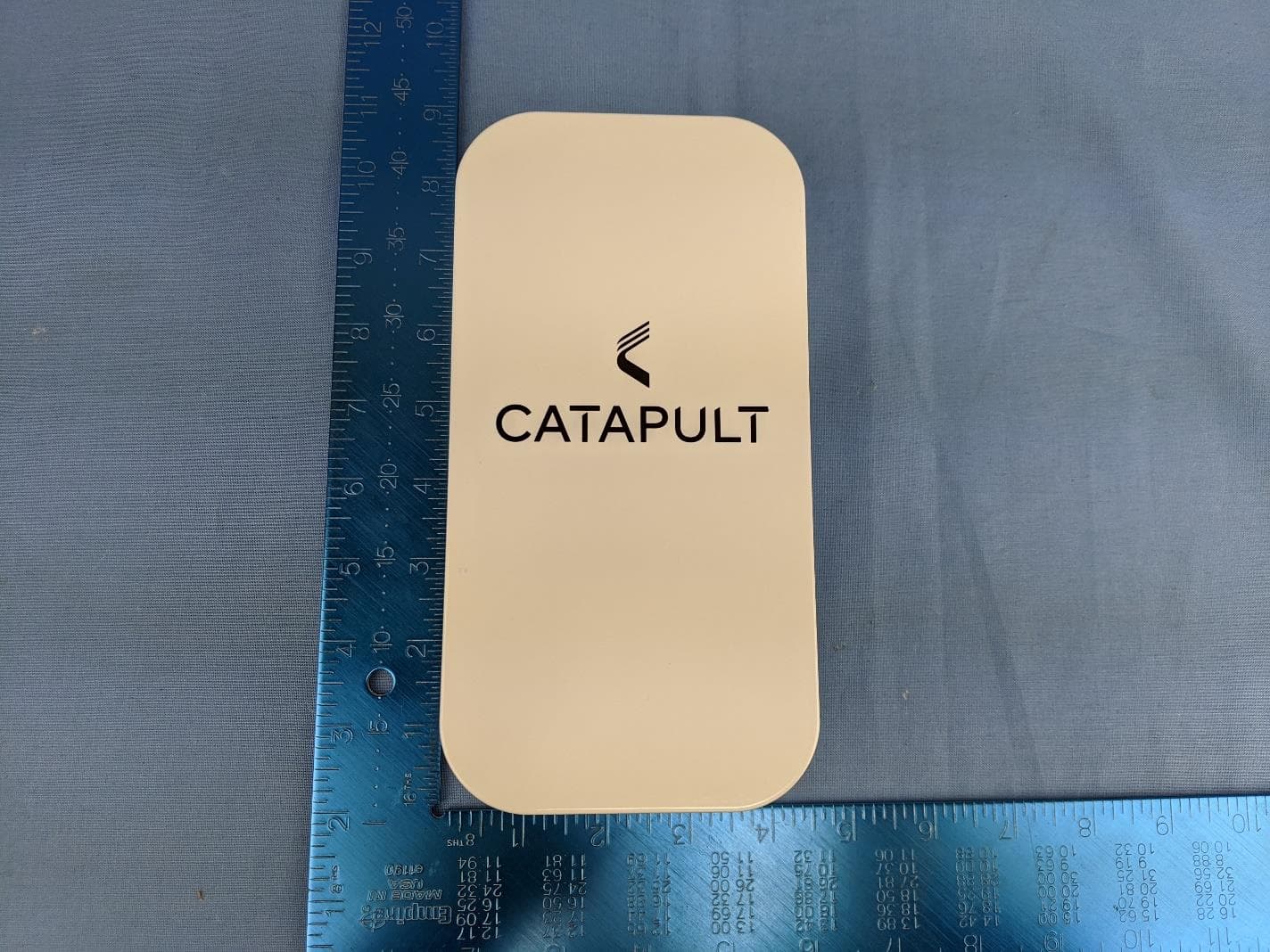
2ADAL-VR7601
Apr 28, 2022Vector Portable Receiver
Equipment Class
WBT - Wideband Transmitter