2ADB4-W-T03-05X001AWPCTX-PAD
Foxconn Interconnect Technology Limited Taiwan Branch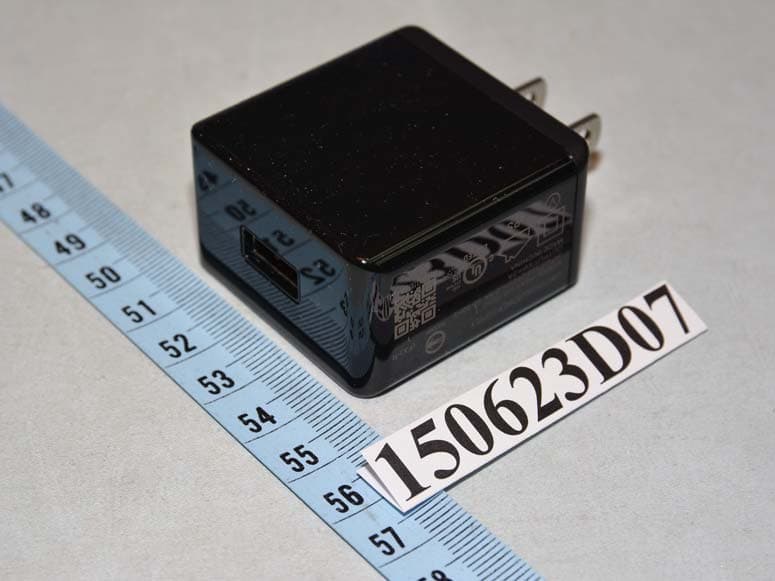
Click to zoom
Application Details
- Equipment Class
- DCD - Part 15 Low Power Transmitter Below 1705 kHz
- Date of Grant
- Nov 01, 2015
- Application Purpose
- Original Equipment
- Date of Application
- Nov 01, 2015
- Equipment Note
- WPCTX-PAD
- Frequency Range
- 0.12700000 - 0.12700000
- Country
- Taiwan
Documents & Files
Document Text
Text extracted from the exhibit documents filed with the FCC. Open a document above to read the original.
Users Manual
© 2014 Rattan Digital Inc.版权所有 Ver . 1.0 產品型號:W-T03-05X001A, W-R01-051001AW-R01-052001AW-R01-053001A 1.產品介紹 擺脫束縛,拿起放下,追求自由生活。 Rattan 無線充電套裝給您更自由的充電方式,更極致的用戶體驗,更高端的生活品質。 本產品適合於手機、MP3、MP4、數碼產品及其他3C產品來進行無線充電的功能,符合WPC Qi V1.1標準。接收器精巧的外觀 根據法國特色美食Macaron設計而來,讓人一見傾心;發射器絢麗的燈光,超薄的厚度,帶給您更好的體驗。 2.產品包裝內容 .1個Qi平板發射器 . 1個Qi馬卡龍接收器 . 1條5V/2A充電器線纜 . 1個電源供應器(Output:5V/2A) . 1份說明書 3.產品特點 Qi平板發射器: .符合WPC Qi V1.1標準 . 靈活的定位 . 超薄設計 . 絢麗燈光效果 4.產品零件圖示 5.產品操作步驟 .步驟 1 將充電器纜線一端連接至Qi平板發射器,另一端連接至電源供應器,並將電源供應器插入牆上的插座。 . 步驟 2 確保將電源供應器插入電源插座,並將Qi平板發射器的周圍區域清空,Qi平板發射器底部將循環亮紅燈、綠燈、藍燈、黃 燈、紫燈和青燈。 . 步驟 3 將Qi馬卡龍接收器連接到您的手機。 (iPhone 5/5S、HTC 、三星、諾基亞、索尼等) . 步驟 4 確認Qi平板發射器上沒有任何物品,將Qi馬卡龍接收器放到Qi平板發射器上的中間位置。 . 步驟 5 當Qi馬卡龍接收器直接放到Qi平板發射器上的有效充電範圍內,Qi馬卡龍接收器的綠燈恆亮;當Qi馬卡龍接收器放到其正 確位置開始充電,Qi平板發射器的綠燈恆亮。 . 步驟 6 如果Qi馬卡龍接收器和Qi平板發射器連結充電異常或在Qi馬卡龍接收器和Qi平板發射器間有其他金屬(異物偵測),Qi馬卡 龍接收器的綠燈熄滅,Qi平板發射器的紅燈閃爍。 注意: .FOD是Foreign Object Detection縮寫,即異物偵測的意思。 . 如果您的手機與Qi規格相容,您可以將您的手機放到我們Qi平板發射器的中間位置上來充電。 . 如果您的充電發射器與Qi規格相容,您可以使用我們的Qi馬卡龍接收器。 6.產品燈號顯示 6.1指示燈 – Qi平板發射器 .待 機:6色燈循環閃爍 . 充電中:綠燈恆亮 . 發生問題:綠燈閃爍 6.2指示燈 – Qi馬卡龍接收器 .充電中:綠燈恆亮 . 未連接或充電發生問題:綠燈熄滅 7.產品技術規格 7.1Qi平板發射器規格 .輸入電壓: DC 5V . 輸入電流: 1.4~1.8A . 輸出電壓: DC 5V . 輸出電流: 0~1A . FOD功能(異物偵測) 7.2Qi馬卡龍接收器規格 .輸出電壓: DC 5V 9.疑難排解 .問題-1:為什麼我的手機無法充電? . 回答-1: 1.檢查Qi平板發射器上沒有任何異物。 2.確認Qi平板發射器和Qi馬卡龍接收器沒有過熱,如果Qi平板發射器的溫度過高,請將Qi馬卡龍接收器從Qi平板發射器上 拿起,然後關閉Qi平板發射器的電源。 3.當Qi平板發射器降溫後,再重新嘗試充電。 . 問題-2:Qi馬卡龍接收器的指示燈不亮! . 回答-2: 檢查Qi馬卡龍接收器是否正確定位到Qi平板發射器的中心位置,如果沒有,請重新放置Qi馬卡龍接收器到Qi平板發射器的 中心位置直到綠燈恆亮。 . 問題-3:為什麼Qi平板發射器的紅色指示燈在閃爍? . 回答-3: 我們的Qi平板發射器具有檢測異物FOD功能,如果Qi平板發射器和Qi馬卡龍接收器間有異物如金屬或導電物質存在,Qi平板 發射器的紅色指示燈會發生閃爍,請將此異物移開並重新放上連接到您手機的Qi馬卡龍接收器。 . 問題-4:使用馬卡龍接收器和Qi平板發射器來為我的手機充電需要充多久? . 回答-4: 充電時間將取決於手機電池容量大小、Qi平板發射器和Qi馬卡龍接收器對位的準確性與電源端之供電所影響,大約是您使用 有線充電時間的1.3倍。 . 問題-5:可以使用我們自己的USB連接線或電源供應器給Qi平板發射器充電嗎? . 回答-5: 1.為了達到最佳的充電效率,請使用隨附的USB連接線或電源供應器。 2.其他相容的USB連接線亦可以使用,但可能會降低充電效率,還有超過1公尺的連接線也可能會降低其充電效率。 3.建議使用5V 2A的電源供應器,若是低於此規格,將可能會造成充電的效率降低。 Ver . 1.0 Rattan© 2014 All Rights Reserved Product Model: W-T03-05X001A, W-R01-051001AW-R01-052001AW-R01-053001A Qi Wireless Charger Kit Qi Pad Transmitter & Qi Macaron Receiver User Manual Qi無線充電套裝 Qi平板發射器& Qi馬卡龍接收器使用手冊 材料:80克铜板纸 正反两面印刷 478mm 120mm 正面 反面 Qi馬卡龍接收器: . 符合WPC Qi V1.1標準 . 馬卡龍風格設計 . 苗條的扁平線適合任意深度 . 可拆卸的線扣設計 . Lightning and uUSB 兩種接口可供選擇 項次 名稱 1 Qi平板發射器 2 Qi馬卡龍接收器 3 充電器線纜 4 電源供應器(5V/2A) 5 手機 參照Fig.1 4 3 2 1 5 Fig. 1 8.產品保養與維護 .為了正確安全地使用,請按照本手冊中的說明進行操作 . 不要使用延長線 . 請保持手機乾燥,雨水、濕氣和各種液體或水分都可能含有腐蝕電路的礦物質 . 如果您的裝置受潮,請讓您的裝置完全乾燥 . 請勿將此裝置移作他用,不要使用損壞的線纜、電源供應器及裝置 . 請勿嘗試為損壞的裝置進行充電,或不與Qi相容的裝置充電 . 請勿將本裝置存放在高溫環境,高溫可能會縮短裝置的壽命,並使其塑膠零件變形或熔化 . 請勿將本裝置存放在低溫環境,當本裝置恢復到常溫時,其內部會有濕氣凝結,可能會損及電路 . 粗暴的使用方式會破壞本裝置內部的電路板和機構 . 請勿扔擲、敲擊或搖晃本裝置 . 只能使用乾淨的軟布清潔裝置表面 . 嚴密監督此裝置遠離兒童 . 輸出電流: 0.1~1A 1.Product Introduction Release your electronic devices; enjoy your life more freely. Rattan Wireless Charging Kit will make your life better with free and comfortable charging experience.WPC (Wireless Charger Kit) is suitable for digital products like MP3, MP4, mobile and other 3C products to charge wirelessly. It completely meets with the standard of WPC Qi V1.1. The delicate receiver is designed as Classic French Macaron which will make you fall in love at the first sight. The Transmitter shines with colorful light in turns when charging. The ultrathin thickness makes your charging experience more comfortable. 2.Packed Contents .1 set of Qi Pad Transmitter . 1 set of Qi Macaron Receiver . 1 USB to micro USB Cable . 1 set of AC Adapter (Output : 5V / 2A) . 1 copy of user manual 3.Functional Features Qi Pad Transmitter: . Qi V1.1 Compatible . Flexible Orientation . Ultra Slim Design 4.Components illustration 5.Operation Steps .Step 1. Connect the Qi Pad Transmitter to the AC adapter by USB to micro USB cable and push the plug into the socket on the wall. . Step 2. Make sure that you plug the AC adapter into the electrical outlet, keep the area around the Qi Pad Transmitter free, the bottom of Qi Pad Transmitter will cycle red light, green light, blue light, yellow light, purple light and cyan light. . Step 3. Connect the Qi Macaron Receiver to your phone. (iPhone 5/5S, HTC, Samsung, Nokia, Sony...etc) . Step 4. Make sure that there’s nothing on the Qi Pad Transmitter surface. Place the Qi Macaron Receive onto the center of Qi Pad Transmitter surface. . Step 5. The green light of Qi Macaron Receiver on when placing Qi Macaron Receiver directly on Qi Pad Transmitter within the range of valid charge; the green light of Qi Pad Transmitter on when the Qi Macaron Receiver is properly positioned and the charging begins. . Step 6. If Qi Macaron Receiver connects with Qi Pad Transmitter abnormally or other metals (FOD) are placed between Qi Macaron Receiver and Qi Pad Transmitter, the green light of Qi Macaron Receiver off and Qi Pad Transmitter flashing red light. Note: .FOD is the abbreviation of Foreign Object Detection. . If your phone has wireless charging meet for WPC Qi compliant, you can put your phone onto center of Qi Pad Transmitter to charge. . If your charging transmitter meet for WPC Qi compliant, you can use with our Qi Macaron Receiver. 6.LED light instruction 6.1 Indicator lights – Qi Pad Transmitter . Standby: Six-color light is flashing . Charging: Green light on . Charging problem: Red light blink 6.2 Indicator lights – Qi Macaron Receiver . Charging: Green light on . No connect or charging problem : Green light off 7.Electrical Performance 7.1 Qi Pad Transmitter . Input Voltage: DC 5V . Input Current: 1.4~1.8A . Output Voltage: DC 5V . Output Current: 0~1A 7.2 Qi Macaron Receiver . Output Voltage: DC 5V . Output Current: 0.1~1A . Support FOD 9.Troubleshooting .Problem-1Why can’t my phone charge it? . Solution-1 1. Check that no other object is on the Qi Pad Transmitter Surface. 2. Make sure the Qi Pad Transmitter and Qi Macaron Receiver do not get too hot. If this too hot, take the Qi Macaron Receiver off the Qi Pad Transmitter and switch the Qi Pad Transmitter off. 3. Try charging again when the Qi Pad Transmitter has cooled down. . Problem-2The indicat…
Text truncated - open the document above for the full version.
External Photos
Page 1 CONSTRUCTION PHOTOS OF EUT Page 2 Page 3
Internal Photos
Page 4 Page 5 Page 6 Page 7 Page 8
Operational Description
FCC ID: 2ADB4-W-T03-05X001A Report No.: RF150623D07 Operational Description This device is a WPCTX-PAD. The transmitter of the EUT is powered by 5Vdc. The antenna is Loop antenna without connector. For more detailed instruction, please take a look at the user’s manual.
Test Report
Report No.: RF150623D07 Page No. 1 / 25 Report Format Version: 6.1.1 FCC Test Report Report No.: RF150623D07 FCC ID: 2ADB4-W-T03-05X001A Test Model: W-T03-05X001A Received Date: Jun. 25, 2015 Test Date: Jul. 22 ~ 24, 2015 Issued Date: Jul. 31, 2015 Applicant: FOXCONN INTERCONNECT TECHNOLOGY LIMITED TAIWAN BRANCH Address: NO.66-1, ZHONGSHAN RD., TUCHENG DIST., NEW TAIPEI CITY 236, TAIWAN (R.O.C.) Issued By: Bureau Veritas Consumer Products Services (H.K.) Ltd., Taoyuan Branch Lab Address: No. 47-2, 14th Ling, Chia Pau Vil., Lin Kou Dist., New Taipei City, Taiwan (R.O.C.) This report is for your exclusive use. Any copying or replication of this report to or for any other person or entity, or use of our name or trademark, is permitted only with our prior written permission. This report sets forth our findings solely with respect to the test samples identified herein. The results set forth in this report are not indicative or representative of the quality or characteristics of the lot from which a test sample was taken or any similar or identical product unless specifically and expressly noted. Our report includes all of the tests requested by you and the results thereof based upon the information that you provided to us. You have 60 days from date of issuance of this report to notify us of any material error or omission caused by our negligence, provided, however, that such notice shall be in writing and shall specifically address the issue you wish to raise. A failure to raise such issue within the prescribed time shall constitute your unqualified acceptance of the completeness of this report, the tests conducted and the correctness of the report contents. Unless specific mention, the uncertainty of measurement has been explicitly taken into account to declare the compliance or non-compliance to the specification. The report must not be used by the client to claim product certification, approval, or endorsement by TAF or any government agencies. Report No.: RF150623D07 Page No. 2 / 25 Report Format Version: 6.1.1 Table of Contents Release Control Record .................................................................................................................................. 3 1 Certificate of Conformity ...................................................................................................................... 4 2 Summary of Test Results ..................................................................................................................... 5 2.1 Measurement Uncertainty ................................................................................................................... 5 2.2 Modification Record ............................................................................................................................ 5 3 General Information .............................................................................................................................. 6 3.1 General Description of EUT ................................................................................................................ 6 3.2 Description of Test Modes ................................................................................................................... 7 3.2.1 Test Mode Applicability and Tested Channel Detail ............................................................................. 8 3.3 Description of Support Units ............................................................................................................... 9 3.3.1 Configuration of System under Test .................................................................................................. 10 3.4 General Description of Applied Standards ......................................................................................... 11 4 Test Types and Results ...................................................................................................................... 12 4.1 Radiated Emission and Bandedge Measurement ............................................................................. 12 4.1.1 Limits of Radiated Emission and Bandedge Measurement .............................................................. 12 4.1.2 Test Instruments ................................................................................................................................ 13 4.1.3 Test Procedures ................................................................................................................................. 14 4.1.4 Deviation from Test Standard ............................................................................................................ 14 4.1.5 Test Set Up ........................................................................................................................................ 15 4.1.6 EUT Operating Conditions ................................................................................................................. 15 4.1.7 Test Results ....................................................................................................................................... 16 4.2 Conducted Emission Measurement .................................................................................................. 18 4.2.1 Limits of Conducted Emission Measurement .................................................................................... 18 4.2.2 Test Instruments ................................................................................................................................ 18 4.2.3 Test Procedures ................................................................................................................................. 19 4.2.4 Deviation from Test Standard ............................................................................................................ 19 4.2.5 Test Setup ...............................................................................................................…
Text truncated - open the document above for the full version.
Test Setup Photos
1 of 3 PHOTOGRAPHS OF THE TEST CONFIGURATION Conducted Emission Test (Mode A) 2 of 3 Conducted Emission Test (Mode B) 3 of 3 Radiated Emission Test
Contact Information
Applicant
May Tan
Test Firm
Bureau Veritas CPS (H.K.) Ltd., Taoyuan BranchRichard Chen
Technical Specifications
| # | Rule Parts | Frequency Range | Power Output |
|---|---|---|---|
| 1 | 15C | 0.127 MHz - 0.127 MHz | - |
Other Applications from Foxconn Interconnect Technology Limited Taiwan Branch
2ADB4-UWBA01
Jul 17, 2026UWBA Anchor
Equipment Class
UWB - Ultra Wideband Transmitter
2ADB4-WA-CBZB3
Mar 10, 2026onn QI2 PAD
Equipment Class
DCD - Part 15 Low Power Transmitter Below 1705 kHz2ADB4-AM-5CF1P30
Jan 12, 2026Wireless Charging Stand
Equipment Class
DCD - Part 15 Low Power Transmitter Below 1705 kHz2ADB4-AM-5CF1P20
Jan 12, 20262 in 1 Wireless Charging Station
Equipment Class
DCD - Part 15 Low Power Transmitter Below 1705 kHz
2ADB4-SEDONA
Mar 11, 2021Sled Server
Equipment Class
DXX - Part 15 Low Power Communication Device Transmitter