2ADC5SRAT10-BKActive Floorstanding Loudspeaker System
3SIXTY INDUSTRIES INC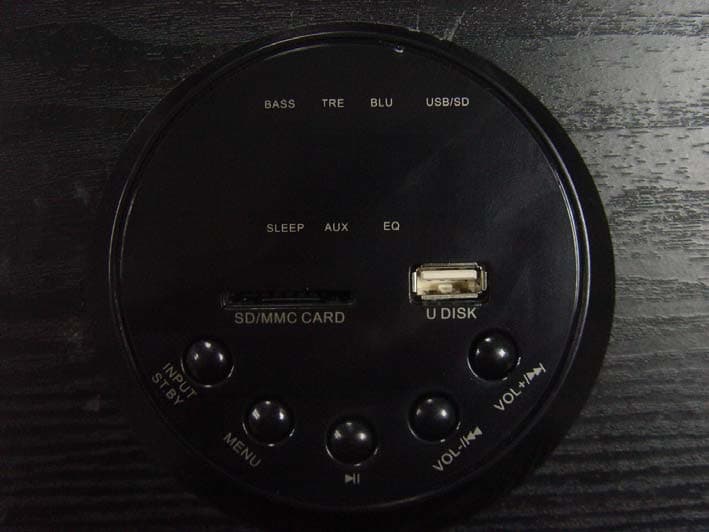
Click to zoom
Application Details
- Equipment Class
- DSS - Part 15 Spread Spectrum Transmitter
- Date of Grant
- Oct 25, 2014
- Application Purpose
- Original Equipment
- Date of Application
- Oct 25, 2014
- Equipment Note
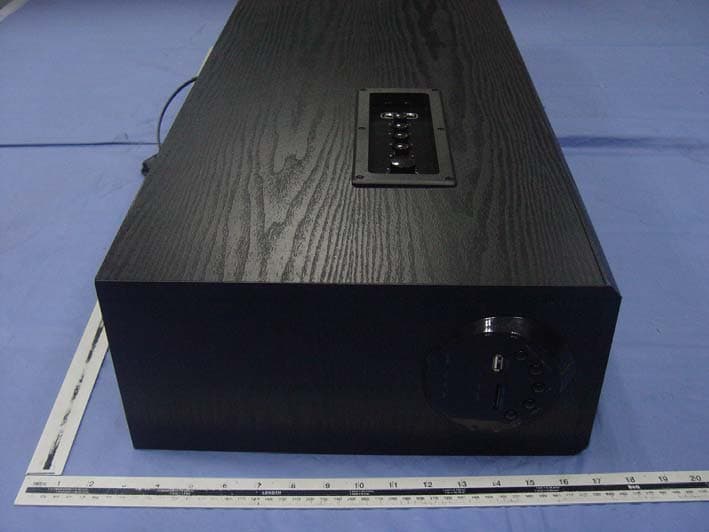
- Active Floorstanding Loudspeaker System
- Frequency Range
- 2402.00000000 - 2480.00000000
- Company
- 3SIXTY INDUSTRIES INC
- Country
- United States
Documents & Files
Document Text
Text extracted from the exhibit documents filed with the FCC. Open a document above to read the original.
Users Manual
SRAT10-BK SHAKER SERIES ACTIVE FLOORSTANDING LOUDSPEAKERS 2 Thank you for your interest in VM Audio products. Our goal is to enhance your listening experience. The Shaker Series was designed as the economical solution for a performance craving, casual consumer. The experts and engineers at VM Audio have meticulously tested and designed this product with a reasonable price tag to fit any budget. Let the Shaker Series maximize the value of your investment. Welcome! About This Manual This user guide describes the controls on the speaker system. You can use the controls on the remote if they have the same or similar names as those on the control panel. Specifications Loudspeaker Type Cabinet Color High Frequency Midrange Driver Bass Driver Audio Input Frequency Range Power (RMS/Peak) Dimensions (H x W x D) Operating Voltage Bluetooth Wireless Range Microphone Input Jack Full Range System Phantom Black 1 1/2” Composite Soft Dome 4” Treated Composite Fiber 8” Dual Pulp Cone Analog RCA, Bluetooth, USB, SD 40 Hz - 20 kHz 300W / 1000W 32.68” x 6.38” x 12.20” 120V 30 ft. 1/4” / 6.3mm 3 Table of Contents 2 2 3 4 5 6 7 8 18 22 37 40 41 42 Welcome Specifications Table of Contents Warning Precautions System Features Included Overview Connections Settings & Adjustments Operation Speaker Placement Troubleshooting Warranty 4 Warning! To prevent fire or electric shock: • Do not expose the unit to rain or moisture. • Do not open the cabinet. • Do not use these speakers near water. • Do not expose these speakers to dripping or splashing liquids • Do not set objects containing liquids on units. • Do not spill liquids into any part of the speaker system. • Do not overload wall outlets and extension cords. • Do not run power cables and speaker wires through sharp edges. • Do not pinch power cables and speaker wires. • Do not expose the bare wires from the power cable and speaker wires. • Do not remove the back amplifier plate. No user-serviceable parts inside. • Refer servicing to qualified personnel only. WARNING RISK OF ELECTRIC SHOCK CAUTION: Any change or modifications not expressly approved in this manual could void your warranty for this equipment. 5 Precautions On Safety • Contact between bare speaker wires may result in a short-circuit. • Should any liquid or solid object fall into the speaker system, unplug the system’s power cord and have the system checked before operating it any further. On Power Sources • Before operating this speaker system, check that the operating voltage of the speaker system is identical to the wall outlet voltage where the speaker is being connected. • If you are not going to use the speaker system for a long period of time, be sure to disconnect the speaker system from the wall outlet. To disconnect the AC power cord (mains lead), grasp the plug itself and never pull the cord. • AC power cord must be changed by qualified electrical personnel. On Placement • Use good lifting practice when moving speakers to avoid injury. • Do not install the speakers in an inclined position. On Operation • Before making any connections, turn off your receiver or audio source and unplug if from the AC (mains) power outlet. Not doing this may result in damage to your system. • The volume level should not be turned up to the point of distortion. On Adjusting Volume • Do not turn up the volume while listening to a portion with very low level inputs or no audio signals. If you do, the speakers may be damaged when a peak level portion is played. On Cleaning • Clean the cabinet, panel and controls with a soft cloth slightly moistened with a mild detergent solution. Do not use any type of abrasive pad, scouring powder or solvent such as alcohol or benzine. 6 System Features • High Performance With Smooth & Detailed Reproduction • Phantom Black Wood Veneer Body • Easy 1-2-3 Direct Play Setup • All-In-One Home Audio Solution • Wide Range 3-Way Soundstage Performance • Fully Powered, Bi-amplified System • Advanced Wireless Bluetooth Connectivity • Internal, Magnetic Motor Shielding Protection • Optimum Bass Reflex Wood Enclosure Design • CAD Energized Bass Port Design • Soft Dome 1.5” High Frequency Driver • High Performance 4” Midrange Driver • Deep Note 8” Solid Bass Subwoofer • Karaoke Function with Dual Mic Input & Echo Control • USB Drive / SD Card Music Playback • WMA / MP3 Music File Compatibility • Bass, Treble, Mic, Echo & Volume Adjustments • Built-In Digital Control POD • High Clarity Class A/B Amplifier Technology • Low Distortion CMOS Signal Processing Technology • Infrared Full Function Wireless Remote Control 7 Review the contents of the package and make sure the following items are included: Included RemoteSpeaker Cabinets RCA-to-RCA Cables20ft Speaker Wire RCA-to-3.5mm CableUser Guide SRAT10-BK SHAKER SERIES ACTIVE FLOORSTANDING LOUDSPEAKERS 8 Right SpeakerLeft Speaker Front View Overview 9 Overview Rear View Amplifier Back Plate Speaker Connector Right SpeakerLeft Speaker 10 Side View Overview Left Speaker Side Panel Control Digital Control Pod 11 Top View Overview Left Speaker Digital Control POD 12 Level Control Panel Overview VOLUME TREBLE BASS MIC. VOL ECHO MIC 13 Amplifier Back Plate Overview Speaker Output Audio Input Jacks Power Cord Power Switch 14 Overview Digital Control POD 14 7 6 5 4 3 2 1 8 9 10 11 12 13 15 15 Digital Control POD Functions Overview 1- 2 - 3 - 4 - 5 - 6 - 7 - 8 - 9 - 10 - 11 - 12 - 13 - 14 - 15 - Input selector / On-OFF wake button. Tone control selector button. Play / Pause control button. Reverse skip function / Volume down button. Forward skip function / Volume up button. LED indicator for bass adjustment. LED indicator for treble adjustment. LED indicator for Bluetooth operation. LED indicator for USB/SD operation. LED indicator for sleep timer function. LED indicator for equalizer preset function. LED indicator for Auxiliary operation. LED display. USB drive input port. SD card input port. 16 Remote Overview 1911 12 2 1 9 5 3 4 17 18 16 15 8 10 6 20 7…
Text truncated - open the document above for the full version.
Cover Letter(s)
SCS-F18: Project and Product Certification Representative Authorization Letter Page 1 of 2 Rev 5.0 775 Montague Expressway Milpitas, CA 95035 Tel: 408-526-1188 Fax: 408-526-1088 Email: [email protected] Project and Product Certification Representative Authorization Letter Revision History Reason for Amendment (current / obsolete) From To Approved Date Initial Release (obsolete) 1.0 1.0 Nov-14-2006 Revised wording (obsolete) 1.0 2.0 Sept–25-2007 Updated company template (obsolete) 2.0 3.0 Jan-31-2012 Updated letter information (obsolete) 3.0 4.0 May-23-2014 Added FCC ID field (current) 4.0 5.0 Sept 16 2014 SCS-F18: Project and Product Certification Representative Authorization Letter Page 2 of 2 Rev 5.0 3SIXTY INDUSTRIES INC 2014-10-16 To: SIEMIC, INC. 775 Montague Expressway, Milpitas, CA 95035 USA Dear Sir/Madam, Re: Product Certification Representative Authorization Letter We, 3SIXTY INDUSTRIES INC hereby authorize SIEMIC, Inc. to act as a Certification Body for certifying for the following project(s): Product Description: Active Floorstanding Loudspeaker System Model name: SRAT10-BK FCC ID: 2ADC5SRAT10-BK Sincerely, Client’s signature Client’s name / title: Eyad Aboabdo / Vice President Contact information / address: 1150 W.CENT RAL AVENUE BLDG C BREA, CALIFONIA 92821 USA
Cover Letter(s)
SCS-F19: Confidentiality Request Letter Page 1 of 2 Rev 3.0 775 Montague Expressway Milpitas, CA 95035 Tel: 408-526-1188 Fax: 408-526-1088 Email: [email protected] Confidentiality Request Letter Revision History Reason for Amendment (current / obsolete) From To Approved Date Initial Release (obsolete) 1.0 1.0 Nov-14-2006 Adding CFR 2.459 (obsolete) 1.0 2.0 August – 11 - 2008 Updated company template & Added text box (current) 2.0 3.0 Jan-31-2012 SCS-F19: Confidentiality Request Letter Page 2 of 2 Rev 3.0 3SIXTY INDUSTRIES INC 2014-10-16 To: Federal Communications Commission Authorization and Evaluation Division 7435 Oakland Mills Road Columbia, MD Subject: Permanent Confidentiality Request for FCC ID: 2ADC5SRAT10-BK We hereby request confidential treatment of information accompanying this application as outlined below: - Block Diagram - Operational Description - Schematic The above materials contain trade secrets and proprietary information not customarily released to the public. The public disclosure of these materials may be harmful to the applicant and provide unjustified benefits to its competitors. The applicant understands that pursuant to Section 0.457 & 0.459 of the Rules, disclosure of this application and all accompanying documentation will not be made before the date of the Grant for this application. Sincerely, Client’s signature Client’s name / title: Eyad Aboabdo / Vice President Contact information / address: 1150 W.CENT RAL AVENUE BLDG C BREA, CALIFONIA 92821 USA
Internal Photos
Antenna
RF Exposure Info
FCC ID : 2ADC5SRAT10-BK 1. RF EXPOSURE 1.1. The Requirement System operating under the provisions of this section shall be operated in a manner that ensures that the public is not exposed to radio frequency energy levels in excess of the Commission’s guidelines. See Section 15.247(b)(4) and Section 1.1307(b)(1) 1.2. Limit For Maximum Permissible Exposure (MPE) Limits for General Population/ Uncontrolled Exposure F = frequency in MHz, * Plane-wave equivalent power density 1.3. MPE Calculation Method Predication of MPE limit at a given distance Equation from page 18 of OET Bulletin 65, Edition 97-01 S=PG/4πR² Where: S=power density P=power input to antenna G=power gain of the antenna in the direction of interest relative to an isotropic radiator R=distance to the center of radiation of the antenna Frequency Range (MHz) Electric Field Strength (E) (V/m) Magnetic Field Strength (H) (A/m) Power Density (S) ( 2 mW/cm) Averaging Time 2 E, 2 H or S (minutes) 0.3-1.34 614 1.63 (100)* 30 1.34-30 824/f 2.19/f (180/f)* 30 30-300 27.5 0.073 0.2 30 300-1500 f/1500 30 1500-100,000 1.0 30 From the peak EUT RF output power, the minimum mobile separation distance, d=0.2m, as well as the gain of the antenna is 0 dBi, the RF power density can be obtained. 1.4. TEST RESULTS Maximum measured transmitter power GFSK Mode Test Frequency (MHz) Minimum Separation Distance (cm) Output Power (dBm) Output Power (mW) Antenna Gain (Numeric) Power Density Limit (mW/cm 2 ) Power Density At 20 cm (mW/cm 2 ) Test Results 2402 20.00 -0.82 0.83 1.000 1.000 0.0002 Pass 2441 20.00 -1.15 0.77 1.000 1.000 0.0002 Pass 2480 20.00 -1.28 0.74 1.000 1.000 0.0001 Pass ∏/4-DQPSK Mode Test Frequency (MHz) Minimum Separation Distance (cm) Output Power (dBm) Output Power (mW) Antenna Gain (Numeric) Power Density Limit (mW/cm 2 ) Power Density At 20 cm (mW/cm 2 ) Test Results 2402 20.00 -3.43 0.45 1.000 1.000 0.0001 Pass 2441 20.00 -3.89 0.41 1.000 1.000 0.0001 Pass 2480 20.00 -3.94 0.40 1.000 1.000 0.0001 Pass 8DPSK Mode Test Frequency (MHz) Minimum Separation Distance (cm) Output Power (dBm) Output Power (mW) Antenna Gain (Numeric) Power Density Limit (mW/cm 2 ) Power Density At 20 cm (mW/cm 2 ) Test Results 2402 20.00 -3.18 0.48 1.000 1.000 0.0001 Pass 2441 20.00 -3.59 0.44 1.000 1.000 0.0001 Pass 2480 20.00 -3.72 0.42 1.000 1.000 0.0001 Pass The measurement results comply with the FCC Limit per 47 CFR 2.1091 for the uncontrolled RF Exposure. 1.5. FCC Radiation Exposure Statement This equipment complies with FCC radiation exposure limits set forth for an uncontrolled environment. In order to avoid the possibility of exceeding the FCC radio frequency exposure limits, Human proximity to the antenna shall not be less than 20cm(8 inches) during normal operation. Proposed RF exposure safety information to include in User’s Manual.
Test Report
REPORT NO. ATE20141954 Page 1 of 93 FCC ID: 2ADC5SRAT10-BK ACCURATE TECHNOLOGY CO. LTD APPLICATION CERTIFICATION On Behalf of 3SIXTY INDUSTRIES INC Active Floorstanding Loudspeaker System Model No.: SRAT10-BK FCC ID: 2ADC5SRAT10-BK Prepared for : 3SIXTY INDUSTRIES INC Address : 1150 W.CENTRAL AVENUE BLDG C BREA, CALIFONIA 92821 USA Prepared by : ACCURATE TECHNOLOGY CO. LTD Address : F1, Bldg. A, Changyuan New Material Port, Keyuan Rd. Science & Industry Park, Nanshan, Shenzhen, Guangdong P.R. China Tel: (0755) 26503290 Fax: (0755) 26503396 Report Number : ATE20141954 Date of Test : Oct 08-22,2014 Date of Report : Oct 22,2014 REPORT NO. ATE20141954 Page 2 of 93 FCC ID: 2ADC5SRAT10-BK ACCURATE TECHNOLOGY CO. LTD TABLE OF CONTENTS Description Page Test Report Certification 1. GENERAL INFORMATION .......................................................................................................... 5 1.1. Description of Device (EUT)....................................................................................................................5 1.2. Description of Test Facility ......................................................................................................................6 1.3. Measurement Uncertainty.........................................................................................................................6 2. MEASURING DEVICE AND TEST EQUIPMENT ..................................................................... 7 3. OPERATION OF EUT DURING TESTING ................................................................................. 8 3.1. Operating Mode ........................................................................................................................................8 3.2. Configuration and peripherals ..................................................................................................................8 4. TEST PROCEDURES AND RESULTS ......................................................................................... 9 5. 20DB BANDWIDTH TEST............................................................................................................10 5.1. Block Diagram of Test Setup..................................................................................................................10 5.2. The Requirement For Section 15.247(a)(1) ............................................................................................10 5.3. EUT Configuration on Measurement .....................................................................................................10 5.4. Operating Condition of EUT ..................................................................................................................10 5.5. Test Procedure ........................................................................................................................................11 5.6. Test Result ..............................................................................................................................................11 6. CARRIER FREQUENCY SEPARATION TEST........................................................................ 17 6.1. Block Diagram of Test Setup..................................................................................................................17 6.2. The Requirement For Section 15.247(a)(1) ............................................................................................17 6.3. EUT Configuration on Measurement .....................................................................................................17 6.4. Operating Condition of EUT ..................................................................................................................17 6.5. Test Procedure ........................................................................................................................................18 6.6. Test Result ..............................................................................................................................................18 7. NUMBER OF HOPPING FREQUENCY TEST ......................................................................... 24 7.1. Block Diagram of Test Setup..................................................................................................................24 7.2. The Requirement For Section 15.247(a)(1)(iii) ......................................................................................24 7.3. EUT Configuration on Measurement .....................................................................................................24 7.4. Operating Condition of EUT ..................................................................................................................24 7.5. Test Procedure ........................................................................................................................................25 7.6. Test Result ..............................................................................................................................................25 8. DWELL TIME TEST ..................................................................................................................... 27 8.1. Block Diagram of Test Setup..................................................................................................................27 8.2. The Requirement For Section 15.247(a)(1)(iii) ......................................................................................27 8.3. EUT Configuration on Measurement .....................................................................................................27 8.4. Operating Condition of EUT ..................................................................................................................27 8.5. Test Procedure ........................................................................................................................................28 8.6. Test Result ...........…
Text truncated - open the document above for the full version.
Contact Information
Applicant
Eyad Aboabdo(Vice President)
Test Firm
Accurate Technology Co., Ltd.Sean Liu
Technical Specifications
| # | Rule Parts | Frequency Range | Power Output |
|---|---|---|---|
| 1 | 15C | 2.40 GHz - 2.48 GHz | 830.00 µW |
Other Applications from 3SIXTY INDUSTRIES INC
2ADC5EXAT11-BK
Oct 25, 2014Active Floorstanding Loudspeaker System
Equipment Class
DSS - Part 15 Spread Spectrum Transmitter