2ADCY-LD2EA0002Proprietary RFID
Logi-D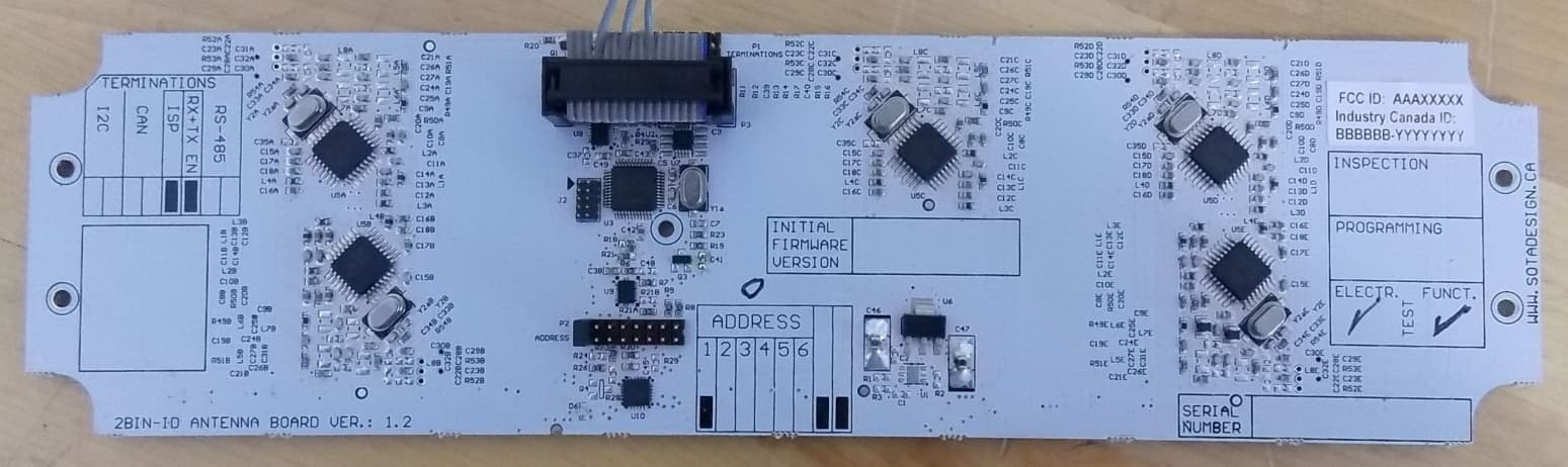
Click to zoom
Application Details
- Equipment Class
- DXX - Part 15 Low Power Communication Device Transmitter
- Date of Grant
- Jan 26, 2015
- Application Purpose
- Original Equipment
- Date of Application
- Jan 26, 2015
- Equipment Note
- Proprietary RFID
- Frequency Range
- 13.56000000 - 13.56000000
- Company
- Logi-D
- Country
- Canada
Documents & Files
Document Text
Text extracted from the exhibit documents filed with the FCC. Open a document above to read the original.
Users Manual
LD2-EA0002 GEN II Antenna Board User Manual ESD (EN) Warning: This module is ESD sensitive. Electrostatic discharges can permanently damage the module. Handle with proper grounding equipment and techniques. (FR) Attention: Ce module est sensible aux décharges électrostatiques, qui peuvent lui infliger des dommages permanents. Manipuler avec l’équipement et les méthodes appropriés de mise à la terre. RF Emission (EN) Warning: This module contains radio-frequency transceivers and antennas which emits and receive in the 13.56 MHz frequency band. This module can interfere with and its functionality can be impacted by other nearby equipment operating in the same frequency band. (FR) Attention: Ce module contient des émetteurs-récepteurs et antennes qui émettent et reçoivent dans la plage fréquentielle de 13.56 MHz. Ce module peut interférer et ses fonctionnalités peuvent être altérées par de l’équipement avoisinant opérant dans la même plage fréquentielle. RF Exposure (EN) Warning: Exposure to Radio Frequency Energy: The radiated power output of the RFID module is below the RF exposure limits for uncontrolled exposure. This device should be operated with a minimum distance of at least 20 cm between the RFID antenna and a person’s body. (FR) Attention: Évaluation d'exposition aux RF: L’intensité de champ RF émis par la carte RFID est inferieures aux limites d'intensité de champ RF prévues pour l’environnement non contrôlé. Les dispositifs à un élément rayonnant fonctionnant normalement à des distances de séparation entre l'utilisateur et le dispositif supérieures à 20 cm. FCC part 15 Warnings FCC 2-parts warning statement under 15.19 This device complies with part 15 of the FCC Rules. Operation is subject to the following two conditions: (1) This device may not cause harmful interference, and (2) this device must accept any interference received, including interference that may cause undesired operation. Modification statement 15.21 The user manual or instruction manual for an intentional or unintentional radiator shall caution the user that changes or modifications not expressly approved by the party responsible for compliance could void the user's authority to operate the equipment. IC warning statement (EN) Warning: This device complies with Industry Canada’s licence-exempt RSSs. Operation is subject to the following two conditions: (1) This device may not cause interference; and (2) This device must accept any interference, including interference that may cause undesired operation of the device. (FR) Attention: Le présent appareil est conforme aux CNR d'Industrie Canada applicables aux appareils radio exempts de licence. L'exploitation est autorisée aux deux conditions suivantes : (1) l'appareil ne doit pas produire de brouillage, et (2) l'utilisateur de l'appareil doit accepter tout brouillage radioélectrique subi, même si le brouillage est susceptible d'en compromettre le fonctionnement. Labelling Requirements for the Host Device The host device shall have a label with following content: Figure 1:FCC/IC label requirement. Installation The LD2-EA0002 PCB module is to be installed in a Logi-D 2BIN-iD Gen-II product. To function properly, it must be connected to a compliant host computer, like the LD2-EA0001. To install the LD2-EA0002, place the module in the 2Bin Gen-II enclosure, with the LEDs facing the wall of the enclosure. The components side should face the open side of the enclosure. Secure the module in place with five (5) screws. Connect the ribbon cable from the host controller in the IDC connector. Addressing Install the jumpers on the P2 header to assign an address to the module. Terminations If the module is the last on the ribbon cable, insert the termination jumper on positions 7 and 8.
Cover Letter(s)
Modular approval Declaration letter – FCC rev2 Product: 2BIN-iD Model: LD2-EA0002 FCC ID: 2ADCY-LD2EA0002 The device complies with limited modular transmitter approval as per 15.212 and 996369 D01 Module Equip Auth Guide v01r04. Requirements: 1) The radio elements must have the radio frequency circuitry shielded. Physical components and tuning capacitor(s) may be located external to the shield, but must be on the module assembly. Answer :No 2) The modular transmitter must have buffered modulation/data inputs (if such inputs are provided) to ensure that the module will comply with part 15 requirements under conditions of excessive data rates or over-modulation. Answer :Yes Description:All inputs to the modules are buffered through logic or microprocessor inputs. 3) The modular transmitter must have its own power supply regulation. Answer :No – its powered by an external 5V DC. 4) The module must contain a permanently attached antenna, or contain a unique antenna connector, and be marketed and operated only with specific antenna(s), per Sections 15.203, 15.204(b), 15.204(c), 15.212(a), 2.929(b). Answer :Yes Description : Permanent PCB circuitry antenna (5) The module must demonstrate compliance in a stand-alone configuration; Answer : No Description :The device was tested with hosted housing. (6) The module must be labelled with its permanently affixed FCC ID label, or use an electronic display (See KDB Publication 784748 about labelling requirements); Answer :Yes Description:The module has a permanent fixed label. (7) The module must comply with all specific rules applicable to the transmitter including all the conditions provided in the integration instructions by the grantee; Answer :Yes, Description:The module comply with all specific rules applicable to the transmitter including all the conditions provided in the integration instructions by the grantee. Upon approval , only Logi-D will use the module as part of custom made Inventory Management Systems. Refer to test report and user manual . (8)The modular transmitter must comply with any applicable RF exposure Answer :Yes Description:Transmitter meets MPE calculation of 47 CFR 1.1307 and KDB Publication 447498 D01 General RF Exposure Guidance v05r02, and the user manual clearly states the RF Exposure warnings. FCC part 15.212 (b) requirement. “-----The applicant for certification must state how control of the end product into which the module will be installed will be maintained such that full compliance of the end product is always ensured.” Answer :Yes Description:Upon approval , only Logi-D will use the module as part of its own devices custom made to support Logi-D Inventory Management Systems. This demonstrates that Logi-D will retain control over the final installation of the device, such that compliance of the end product is assured
External Photos
Section 1 Detailed photos Section λ. Detailed photos Figure Error! No text of specified style in document.‐υ: RF Module bottom view Figure Error! No text of specified style in document.‐φ: RF Module top view
ID Label/Location Info
Logi - D Title : FCC/ IC Label Drawing Document Number : LD2-EA0002 FC C/IC Label Drawing Rev. 1 Date : 06/01/2015 Sheet : 1/1 Model Label Dimension : 30.8 mm x 9 mm Font : Arial Font Size : 5.8
ID Label/Location Info
Component Side Ribbon Connector FCC & IC Label Location H G F E D C B A H G F E D C B A 1234567891011 1234567891011 Date:28/11/2014 2:59:34 PMSheet:1/1 REV: TITLE: Document Number: LD2-EA0002 Label Location Logi-D Label Location
Internal Photos
Section 1 Detailed photos Section λ. Detailed photos Figure Error! No text of specified style in document.‐υ: RF Module bottom view Figure Error! No text of specified style in document.‐φ: RF Module top view
Test Report
www.nemko.com Nemko Canada Inc., a testing laboratory, is accredited by the Standards Council of Canada. The tests included in this report are within the scope of this accreditation FCC 15.225.docx; Date: June 2013 SCC Accredited LAB LAB Accrédité CCN TM ONE WORLDOURAPPROVAL Test report 250056-1R2TRFWL Date of issue: January 21, 2015 Applicant: Logi-D Product: 2BIN-iD Model: LD2-EA0002 FCC ID: IC Registration number: 2ADCY-LD2EA0002 12416A-LD2EA0002 Specifications: FCC 47 CFR Part 15 Subpart C, §15.225 Operation within the band 13.110–14.010 MHz RSS-210 Issue 8, Annex 2.6 Devices operating within the 13.110–14.010 MHz band Report reference ID: 250056-1R2TRFWL Page 2 of 29 Lab and test locations Company name Nemko Canada Inc. Designation number CA2040 Site number: FCC test site registration number: 176392 (3 m semi anechoic chamber) Facility Name Ottawa Address 303 River Road City Ottawa Province ON Postal code K1V 1H2 Country Canada Telephone +1 613 737 9680 Facsimile +1 613 737 9691 Toll free +1 800 563 6336 Website www.nemko.com Tested by David Duchesne, Senior EMC/Wireless Specialist and Andrey Adelberg, Senior Wireless/EMC Specialist Reviewed by Kevin Rose, Wireless/EMC Specialist Review date January 21, 2015 Reviewer signature Limits of responsibility Note that the results contained in this report relate only to the items tested and were obtained in the period between the date of initial receipt of samples and the date of issue of the report. This test report has been completed in accordance with the requirements of ISO/IEC 17025. All results contain in this report are within Nemko Canada’s ISO/IEC 17025 accreditation. Copyright notification Nemko Canada Inc. authorizes the applicant to reproduce this report provided it is reproduced in its entirety and for use by the company’s employees only. Any use which a third party makes of this report, or any reliance on or decisions to be made based on it, are the responsibility of such third parties. Nemko Canada Inc. accepts no responsibility for damages, if any, suffered by any third party as a result of decisions made or actions based on this report. © Nemko Canada Inc. Report reference ID: 250056-1R2TRFWL Page 3 of 29 Table of contents Table of contents .......................................................................................................................................................................................................... 3 Section 1. Report summary ................................................................................................................................................................................. 4 1.1 Applicant and manufacturer .................................................................................................................................................................................... 4 1.2 Test specifications .................................................................................................................................................................................................... 4 1.3 Statement of compliance ......................................................................................................................................................................................... 4 1.4 Exclusions ................................................................................................................................................................................................................. 4 1.5 Test report revision history ...................................................................................................................................................................................... 4 Section 2. Summary of test results ....................................................................................................................................................................... 5 2.1 FCC Part 15 Subpart C, general requirements test results ........................................................................................................................................ 5 2.2 FCC Part 15 Subpart C, intentional radiators test results.......................................................................................................................................... 5 2.3 IC RSS-GEN, Issue 4 test results ................................................................................................................................................................................ 5 2.4 IC RSS-210, Issue 8, Annex 2.6 test results ............................................................................................................................................................... 5 Section 3. Equipment under test (EUT) details ..................................................................................................................................................... 6 3.1 Sample information .................................................................................................................................................................................................. 6 3.2 EUT information ....................................................................................................................................................................................................... 6 3.3 Technical information .............................................................................................................................................................................................. 6 3.4 Product description and theory of operation ........................................................................................................................................................... 6 3.5 EUT exercise details ............................................................................................................................…
Text truncated - open the document above for the full version.
Test Setup Photos
Test Set Up Photos Report reference ID: 250056-1R1TRFWL
Contact Information
Applicant
Frederic Boyer(IT & R&D Manager)
Test Firm
Nemko Canada Inc. (Ottawa)Charles Neal
Technical Specifications
| # | Rule Parts | Frequency Range | Power Output |
|---|---|---|---|
| 1 | 15C | 13.56 MHz - 13.56 MHz | - |