2ADCZ-NWRM1000Smart Radio Module
Nwave Technologies Inc.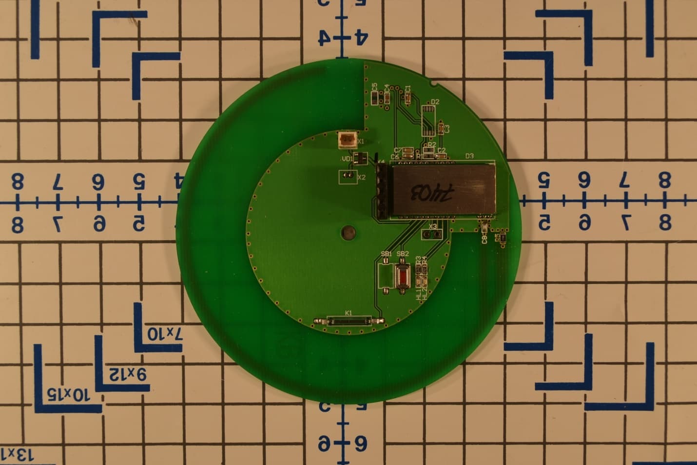
Click to zoom
Application Details
- Equipment Class
- DSS - Part 15 Spread Spectrum Transmitter
- Date of Grant
- Nov 17, 2014
- Application Purpose
- Original Equipment
- Date of Application
- Nov 17, 2014
- Equipment Note
- Smart Radio Module
- Frequency Range
- 915.87500000 - 917.10000000
- Company
- Nwave Technologies Inc.
- Country
- United States
Documents & Files
Document Text
Text extracted from the exhibit documents filed with the FCC. Open a document above to read the original.
Users Manual
NWRM1000 User Manual The NWRM1000 communicates with the host MCU over a standard asynchronous serial interface consisting of TX and RX pins. The radio module has got embedded AT commands interpreter to adjust settings and sends messages via NWave radio protocol. Over this serial interface, the NWRM device provides a standard Hayes “AT” command set used to control the module using ASCII readable commands and get answers, as well as to send or receive data. This interface allows two-‐way UART communication to be performed in low energy modes, using only a few μA during active communication and only 150 nA when waiting for incoming data. Below can be found serial port settings and supported AT commands which external processor shall use. Serial Port Settings By default radio module settings are as follows: • LVTTL electrical level • 9600 bps • 8 data bits • 1 stop bit • No parity • No software/hardware control Bootloader The NWRM1000 module contains an integrated bootloader which allows reflashing the module firmware either over the RX/TX UART connection, or over the air using the built-‐in RF transceiver. ADC The NWRM1000 provides an interface to an integrated low-‐power successive approximation register ADC, capable of a resolution of up to 12 bits at up to 1 Msps or 6 bits at up to 1.86 Msps. The ADC0 and ADC1 pins provide the external interface to the ADC. When not used for ADC operation, these 2 pins can be configured to perform other functions using “AT” configuration commands. Carrying Frequency Syntax: «AT+FREQ=[Carrying_frequency],[Bandwidth]» Whereas «Carrying_frequency» is a value of carrying frequency in Hz, «Bandwidth» is a range inside of which the module sends messages. Example: «AT+FREQ=868000000,25000» Answer in case of success: «Ok» Answer in case of error: «Error» Sending Messages Maximum length of the message is 20 bytes. Syntax: «AT+SEND=[&hex_byte1][&hex_byte2]..[ [&hex_byteN]]» Whereas hex_byte[n] represents data in hex format, n – byte number. Before each byte it's needed to put «$» sign. Syntax: «AT+SEND=$23$0A$5D$5F» In case of success the module answers in 3-‐10 seconds: «Ok» In case of error: «Error» Getting Modem Network Address Syntax: «AT+SERIAL=?» Example: «AT+SERIAL=?» In case of success the module returns number in hex: «0000F556» In case of error: «Error» The NWRM1000 is FCC Approved as module to be installed in other devices. This device should be used only for fixed and mobile applications and if the final product after integration is intended for portable use, a new application and FCC is required. This device complies with Part 15 of the FCC Rules. Operation is subject to the following two conditions: (1) This device may not cause harmful interference, and (2) This device must accept any interference, including interference that may cause undesired operation of the device. The user must refer to below information to meet the FCC's RF exposure rules and regulations when they design: • The system antenna(s) used for this transmitter must be installed to provide a separation distance of at least 20 cm from all the persons and must not be co-located or operating in conjunction with any other antenna or transmitter. Manufacturers of mobile, fixed or portable devices incorporating this module are advised to clarify any regulatory questions and to have their complete product tested and approved for FCC compliance. • NWRM1000 is intended for the OEM integrator only. • The user is required to see the Grant of Equipment document for other restrictions. The following regulatory and safety notices must be published in documentation supplied to the end user of the product or system incorporating an adapter in compliance with local regulations. • Host system including NWRM1000 must be labeled with “Contains transmitter module with FCC ID: 2ADCZNVRM1000”
Attestation Statements
Date : October 9, 2014 Subject : Modular Approval Declaration Letter FCC ID : 2ADCZ-NWRM1000 is seeking FCC equipment authorization as Single Modular Transmitter Single Limited Modular Transmitter Equipment Under Testing (‘EUT’) satisfy the requirement for Single Modular Approval Single Limited Modular Approval as detailed in FCC Public Notice DA00-1407. FCC Requirement of Modular Approval 1. The modular transmitter must have its own RF shielding. YES NO 2. The modular transmitter must have buffered modulation/data inputs. YES NO 3. The modular transmitter must have its own power supply regulation. YES NO 4. The modular transmitter must comply with the antenna requirements of section 15.203 and 15.204(c). YES NO 5. The modular transmitter must be tested in a stand-alone configuration. YES NO 6. The modular transmitter must be labeled with its own FCC ID number. YES NO 7. The modular transmitter must comply with any specific rule or operating requirements applicable to the transmitter and the manufacture must provide adequate instruction along with the module to explain any such requirements. YES NO 8. The modular transmitter must comply with any applicable RF exposure requirements. YES NO Note : Limited modular approval may be granted If EUT does not meet all of the requirement shown above Limited modular approval may be granted in case that the applicant can demonstrate to retain control over the final installation of the device such that compliance of the end product is assured. In that case, an operating condition on the limited modular approval for the module shall state that the module is only designated for the end product manufactured by a specific manufacturer When limited modular approval is sought, the application for equipment certification shall state how control of the end product into which the module will be installed and maintained such that full compliance of the end product is always ensured. It shall be provided that clear and specific instructions describing the conditions limitations and procedures for third- parties to use and/or integrate the module into a host device For non-Software Defined Radio transmitter modules where software is used to ensure compliance of the device, it shall be provided that the technical description of how such control is implemented to ensure to prevent the third party from modifying (see KDB 594280). Compliance of a module in its final configuration is the responsibility of the applicant. A host device will not be considered certified if the instructions regarding antenna configuration provided in the original description, of one or more separately certified modules it contains, were not followed. Example: A separately certified low-power transceiver module using Bluetooth technology which is housed in a desktop computer, laptop or peripheral does not require the overall system to be recertified, if the desktop computer, laptop or peripheral, as a stand-alone unit, complies with all applicable technical standards. _________________________________________________ (Name / Title) Maria Smith-Brackenridge Managing Director (Email Address) [email protected] (Phone number) 214-908-9313 (Address) 1201 International Pkwy. Suite 200 Richardson, TX 75098
Cover Letter(s)
DATE : 10/9/2014 To: Federal Communications Commission Authorization and Evaluation Division 7435 Oakland Mills Road Columbia, MD SUBJECT : Request for Confidentiality for FCC ID : 2ADCZ-NWRM1000 We hereby request confidential treatment of the information accompanying this application as outlined below: LONG-TERM AND SHORT-TERM CONFIDENTIAL LIST LONG-TERM CONFIDENTIAL Exhibit Description 1 Block Diagram 2 Schematics 3 Operational Description 4 SHORT-TERM CONFIDENTIAL (180 DAYS) 5 External Photos 6 Internal Photos 7 Test-Setup Photos 8 User’s Manual The above materials contain trade secrets and proprietary information not customarily released to the public. The public disclosure of these materials may be harmful to the applicant and provide unjustified benefits to its competitors. The applicant understands that pursuant to Section 0.457 & 0.459 of the Rules, disclosure of this application and all accompanying documentation will not be made before the date of the Grant for this application. Sincerely, Signed by: Company Name : NWave Technologies, Inc. Company Address : 1201 International Pkwy. Suite 200 Richardson, TX 75081 Contact Person Name/Title (in print) : Maria Smith-Brackenridge / Managing Director
External Photos
EMCE Project #: 4069 44366 S. Grimmer Blvd Fremont, CA 94538 510-490-4307 Office / 510-490-3441 Fax Page 1 of 2 EUT Photos Module Configuration: Spark PCB - Top View EMCE Project #: 4069 44366 S. Grimmer Blvd Fremont, CA 94538 510-490-4307 Office / 510-490-3441 Fax Page 2 of 2 EUT Photos Module Configuration: Spark PCB – Bottom View [Trace Antenna]
ID Label/Location Info
Labe Label l Locati on
Internal Photos
EMCE Project #: 4069 44366 S. Grimmer Blvd Fremont, CA 94538 510-490-4307 Office / 510-490-3441 Fax Page 1 of 4 Internal Photos Module Configuration: Spark PCB - Top View EMCE Project #: 4069 44366 S. Grimmer Blvd Fremont, CA 94538 510-490-4307 Office / 510-490-3441 Fax Page 2 of 4 Internal Photos Module Configuration: Spark PCB – Bottom View [Trace Antenna] EMCE Project #: 4069 44366 S. Grimmer Blvd Fremont, CA 94538 510-490-4307 Office / 510-490-3441 Fax Page 3 of 4 Internal Photos RF Module – Top EMCE Project #: 4069 44366 S. Grimmer Blvd Fremont, CA 94538 510-490-4307 Office / 510-490-3441 Fax Page 4 of 4 Internal Photos RF Module – Bottom
RF Exposure Info
FCC ID : 2ADCZ-NWRM1000 IC : 12418A-NWRM1000 Test Report # 4082-1 EMCE Engineering, Inc., 44366 S. Grimmer Blvd., Fremont, CA 94538 Page 31 of 32 Tel:510-490-4307 Fax: 510-490-3441 e-mail: [email protected] Accredited by the National Voluntary Laboratory Accreditation Program for the specific scope of Accreditation under Lab Code 200092-0 CFR 47, 15.247:200 Section # RSS 210 Issue 8 Section # Description Results 15.247i RSS Gen (5.5) RF Exposure Requirement PASSED According to §1.1310 and §2.1091 RF exposure is calculated. Prediction of MPE limit at a given distance: S = PG/4πR² S = Power density P = power input to antenna G = power gain of the antenna in the direction of interest relative to an isotropic radiator R = distance to the center of radiation of the antenna RESULTS Max Peak output Power at antenna input terminal (dBm) 12.31 Max Peak output Power at antenna input terminal (mW) 17.02 Prediction distance (cm) 20.00000 Prediction frequency (MHz) 2441.00000 Antenna Gain(typical) (dBi) 1.300 Power density at prediction frequency (mW/cm²) 0.004568 MPE limit for uncontrolled exposure at prediction frequency (mW/cm²) 1.00000
Test Report
FCC ID : 2ADCZ-NWRM1000 IC : 12418A-NWRM1000 Test Report # 4082-1 EMCE Engineering, Inc., 44366 S. Grimmer Blvd., Fremont, CA 94538 Page 1 of 32 Tel:510-490-4307 Fax: 510-490-3441 e-mail: [email protected] Accredited by the National Voluntary Laboratory Accreditation Program for the specific scope of Accreditation under Lab Code 200092-0 Intentional Radiator Test Report Test Standards: FCC Part 15.247 (Subpart C – Intentional Radiators) Industry Canada RSS-210, Issue 8 Prepared For: NWave Techologies, Ltd 1201 International Pkwy. Suite 200 Richardson, Texas 75081 USA Equipment Under Test: Product Name : Smart Radio Module Model Name : NWRM1000 Application Purpose : Original Prepared by: EMCE Engineering, Inc. 44366 S. Grimmer Blvd. Fremont, CA 94538 USA This report only responds to the tested sample and may not be reproduced, except in full, without written approval of the EMCE Engineering, Inc. FCC ID : 2ADCZ-NWRM1000 IC : 12418A-NWRM1000 Test Report # 4082-1 EMCE Engineering, Inc., 44366 S. Grimmer Blvd., Fremont, CA 94538 Page 2 of 32 Tel:510-490-4307 Fax: 510-490-3441 e-mail: [email protected] Accredited by the National Voluntary Laboratory Accreditation Program for the specific scope of Accreditation under Lab Code 200092-0 Revision History Rev. Issue Date Description 0 11/03/14 Initial Issue FCC ID : 2ADCZ-NWRM1000 IC : 12418A-NWRM1000 Test Report # 4082-1 EMCE Engineering, Inc., 44366 S. Grimmer Blvd., Fremont, CA 94538 Page 3 of 32 Tel:510-490-4307 Fax: 510-490-3441 e-mail: [email protected] Accredited by the National Voluntary Laboratory Accreditation Program for the specific scope of Accreditation under Lab Code 200092-0 TABLE OF CONTENTS 1. CUSTOMER INFORMATION 3 2. EUT AND ACCESSORY INFORMATION 4 3. MODIFICATIONS 6 4. SUMMARY OF TEST RESULTS 7 5. STANDARDS AND MEASUREMENT METHODS 8 6. TEST SETUPS 9 7. TEST RESULTS 11 8. TEST EQUIPMENT 32 FCC ID : 2ADCZ-NWRM1000 IC : 12418A-NWRM1000 Test Report # 4082-1 EMCE Engineering, Inc., 44366 S. Grimmer Blvd., Fremont, CA 94538 Page 4 of 32 Tel:510-490-4307 Fax: 510-490-3441 e-mail: [email protected] Accredited by the National Voluntary Laboratory Accreditation Program for the specific scope of Accreditation under Lab Code 200092-0 1.0 CUSTOMER INFORMATION Test Laboratory: EMCE Engineering 44366 S. Grimmer Blvd. Fremont, CA 94538 USA Tel: 510-490-4307, Fax: 510-490-3441 [email protected] FCC registration number : 743299 Test Site : FCC : US5291, IC : 3324A Applicant Name : NWave Techologies, Ltd 1201 International Pkwy. Suite 200 Richardson, Texas 75081 USA Tel: +1-214-908-9313 Contact Person: Yury Birchenko Application Purpose : Original EUT Description Smart Radio Module Product Name Smart Radio Module Model Name : NWRM1000 Applied Standards : FCC Title 47 CFR Part 15 Subpart C (15.247) IC RSS-210, Issue 8:2010(Annex 8)/RSS-GEN, Issue 5:2012 FCC ID : 2ADCZ-NWRM1000 IC : 12418A-NWRM1000 RF Operating Frequency (ies) 915.875 – 917.100 MHz Modulation ASK Emission Designator - Report Number 4082-1 Receipt of EUT : 09/15/14 Date of Testing : 09/15/14 – 10/30/14 Date of Report : 11/03/14 The tests listed in this report have been completed to demonstrate compliance to the standards mentioned in the above table. Contents approved: Name: Bob Cole Title: President FCC ID : 2ADCZ-NWRM1000 IC : 12418A-NWRM1000 Test Report # 4082-1 EMCE Engineering, Inc., 44366 S. Grimmer Blvd., Fremont, CA 94538 Page 5 of 32 Tel:510-490-4307 Fax: 510-490-3441 e-mail: [email protected] Accredited by the National Voluntary Laboratory Accreditation Program for the specific scope of Accreditation under Lab Code 200092-0 2.0 EUT AND ACCESSORY INFORMATION EUT Information Product Specification Description Model Name NWRM1000 Type of Modulation FHSS Number of Channels 50 Operating Frequency Range 915.875 – 917.1 MHz Type of Equipment Portable Extreme Operating Temperature Range -20 C – 55 C Extreme Operating Voltage Range N/A – Battery Powered Type of Antenna Integral Antenna Gain (dBi) 1.3 Transmitter Method of Frequency Generation Synthesized Transmitter Aggregate Data Rate >250kbps Transmitter Duty Type Intermittant Continuous Operation for Testing Purposes? Yes EUT and accessories The table below lists all EUTs and accessories used in the tests. Later in this report, only numbers in the last column are used to refer to the devices in each test. Product Name Model Name S/N Number EUT Smart Radio Module NWRM1000 N/A E0001 Software The computers were equipped with test software provided by the customer. The software was used to control the EUT in the tests. Number of Frequencies to be examined (CFR 47, 15.31(m)): 50 total, 3 frequencies examined (915.875, 916.5, 917.1 MHz). FCC ID : 2ADCZ-NWRM1000 IC : 12418A-NWRM1000 Test Report # 4082-1 EMCE Engineering, Inc., 44366 S. Grimmer Blvd., Fremont, CA 94538 Page 6 of 32 Tel:510-490-4307 Fax: 510-490-3441 e-mail: [email protected] Accredited by the National Voluntary Laboratory Accreditation Program for the specific scope of Accreditation under Lab Code 200092-0 3.0 MODIFICATIONS There were no modifications. FCC ID : 2ADCZ-NWRM1000 IC : 12418A-NWRM1000 Test Report # 4082-1 EMCE Engineering, Inc., 44366 S. Grimmer Blvd., Fremont, CA 94538 Page 7 of 32 Tel:510-490-4307 Fax: 510-490-3441 e-mail: [email protected] Accredited by the National Voluntary Laboratory Accreditation Program for the specific scope of Accreditation under Lab Code 200092-0 4.0 SUMMARY OF TEST RESULTS CFR 47, 15.247:2007 Section # RSS 210 Issue 8 Section # Description Results 15.203 Antenna Requirement PASSED 15.247 (b)(2) RSS-210 (A8.4(1)) Tx Conducted Output Power of The Fundamental PASSED 15.247 (d) RSS-210 (A8.5) Conducted Spurious Emissions of The Fundamental(-20dBc) PASSED 15.247d: 15.209(a)/15.205 RSS-210 (A8.5) RSS-GEN 7.2.2 Radiated Spurious Emissions of the Fundamental – Includes Restricted Band Harmonics PASSED 15.247 (d)/15.209 RSS-210 (A8.5) RSS-GEN 7.2.2 TX Band-Edg…
Text truncated - open the document above for the full version.
Test Setup Photos
EMCE Project #: 4069 44366 S. Grimmer Blvd Fremont, CA 94538 510‐490‐4307 Office / 510‐490‐3441 Fax Page 1 of 2 Test Setup Photos Radiated Emission < 1 Ghz EMCE Project #: 4069 44366 S. Grimmer Blvd Fremont, CA 94538 510‐490‐4307 Office / 510‐490‐3441 Fax Page 2 of 2 Test Setup Photos Module Configuration: Spark
Contact Information
Applicant
Pavel Ilyasov(CEO)
Test Firm
Universal Compliance Labs dba EMCE EngineeringBob Cole
Technical Specifications
| # | Rule Parts | Frequency Range | Power Output |
|---|---|---|---|
| 1 | 15C | 915.875 MHz - 917.1 MHz | 17.02 mW |
Other Applications from Nwave Technologies Inc.
2ADCZ-NPS-4-5
Feb 07, 2023Nwave Wireless Vehicle Detection Sensor
Equipment Class
DTS - Digital Transmission System