2ADER-3210Brickstream 3D+ Camera
NOMi Corporation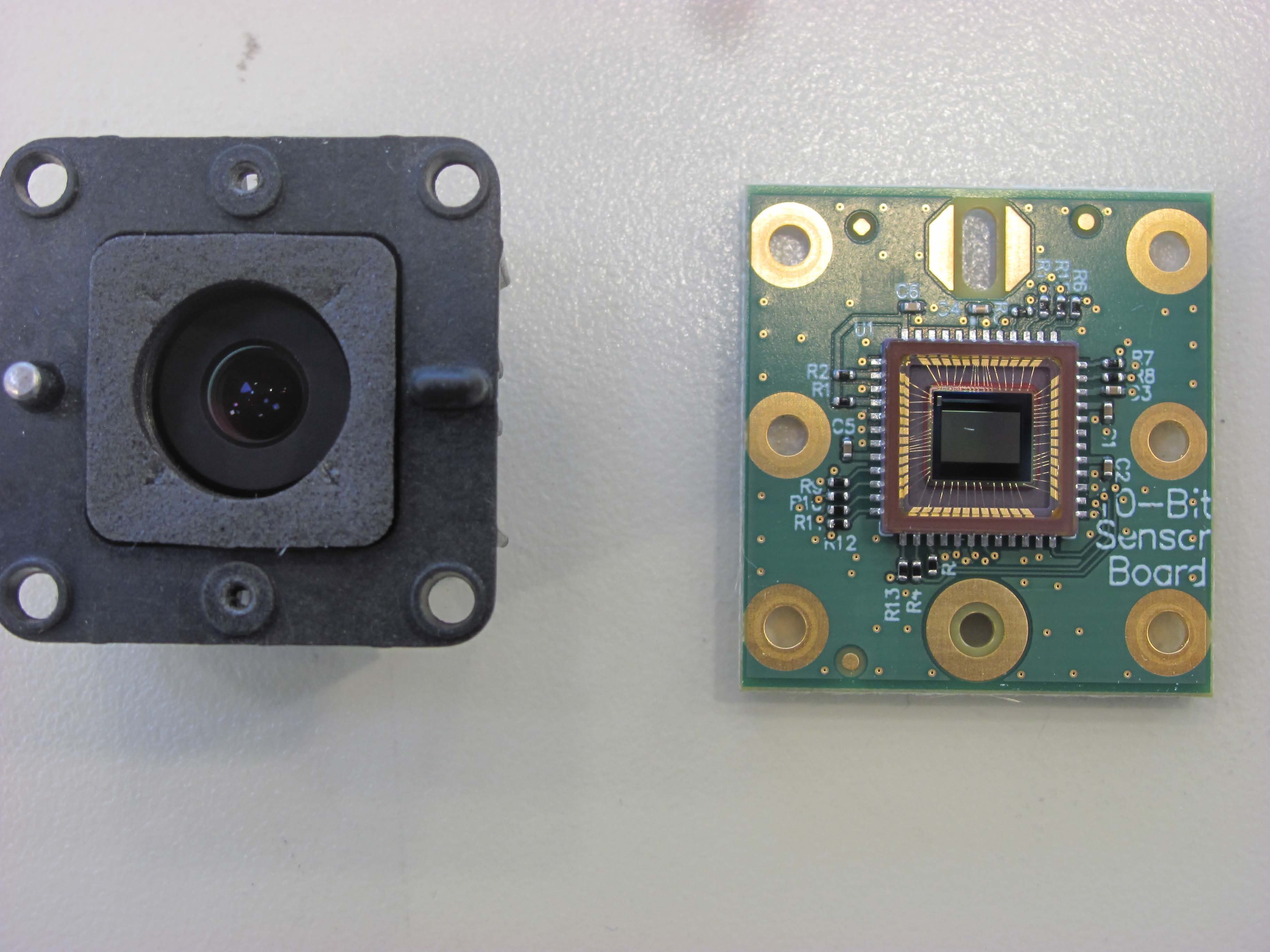
Click to zoom
Application Details
- Equipment Class
- DTS - Digital Transmission System
- Date of Grant
- Jan 14, 2015
- Application Purpose
- Original Equipment
- Date of Application
- Jan 14, 2015
- Equipment Note
- Brickstream 3D+ Camera
- Frequency Range
- 2422.00000000 - 2452.00000000
- Company
- NOMi Corporation
- Country
- United States
Documents & Files
Document Text
Text extracted from the exhibit documents filed with the FCC. Open a document above to read the original.
Users Manual
Brickstream® 3D+ Smart Device Basic Installation Guide Software Version 1.0.0.90 for Brickstream® 3D+ Smart Device, October 2014 Brickstream® 3D+ Basic Installation Guideii | COPYRIGHT & TRADEMARK INFORMATION The product described in this book is a licensed product of Brickstream Corporation. Brickstream’s proprietary information is not to be disclosed or reproduced without written consent. BRICKSTREAM® is a registered service mark of Brickstream Corporation and its Affiliates. QUEUEIQ®, TRAFFICIQ®, and BEHAVIORIQ® are registered trademarks of Brickstream Corporation. Other product names mentioned in this publication may be trademarks or registered trademarks of their respective companies and are hereby acknowledged. Where creation of derivative works, modifications, or copies of this Brickstream copyrighted documentation is permitted under the terms and conditions of an agreement you have with Brickstream, Brickstream’s copyright notice must be included. It is the policy of Brickstream to improve products as new technology, components, software, and firmware become available. Brickstream, therefore, reserves the right to change specifications without prior notice. This edition (Alpha Draft 09-30-2014, October 2014) replaces previously dated versions of this document, the Brickstream® 3D+ Basic Installation Guide. Although this document was believed to be correct at the time of publication, Brickstream Corporation and their affiliates assume no responsibility for errors or omissions. Technical bulletins may be issued at any time to further clarify product installation, maintenance, use, and administration. In the event of any differences, the information in a more recently issued technical bulletin or online help system supersedes correlative information in associated product documentation. All features, functions, and operations described herein may not be marketed by Brickstream in all parts of the world. In some instances, photographs are of equipment prototypes. Therefore, before using this document, consult with your Brickstream representative or Brickstream office for information that is applicable and current. © 2005-2014 Brickstream Corporation. All Rights Reserved Brickstream Corporation, Norcross, Georgia, U.S.A. http://www.brickstream.com Brickstream® 3D+ Basic Installation Guideiii | | COMPLIANCE STATEMENTS Product EMC Compliance This product has been tested and verified to comply with the following electromagnetic compatibility (EMC) regulations. FCC Regulatory Statements This device complies with Part 15 of the FCC Rules. Operation is subject to the condition that this device does not cause harmful interference. This device complies with Part 15 of the FCC Rules. Operation is subject to the following two conditions: (1) this device may not cause harmful interference, and (2) this device must accept any interference received, including interference that may cause undesired operation. NOTE: THE GRANTEE IS NOT RESPONSIBLE FOR ANY CHANGES OR MODIFICATIONS NOT EXPRESSLY APPROVED BY THE PARTY RESPONSIBLE FOR COMPLIANCE. SUCH MODIFICATIONS COULD VOID THE USER'S AUTHORITY TO OPERATE THE EQUIPMENT. RF Exposure Information This equipment complies with FCC radiation exposure limits set forth for an uncontrolled environment. In order to avoid the possibility of exceeding the FCC radio frequency exposure limits, human proximity to the antenna shall not be less than 20 cm during normal operation and must not be collocated or operating in conjunction with any other antenna or transmitter. Electromagnetic Capability (EMC) Directive Conformity is declared to Standards: • CISPR 22:2008-09/EN55022:2006 - Class A - Limits and methods of measurement of radio disturbance characteristics of Information Technology Equipment • CISPR 24: 2010 / EN 55024:2010 - Electromagnetic Compatibility Requirements - Information Technology Equipment - Immunity Characteristics - Limits and Methods of Measurements European Union Notice This equipment complies with the requirements of the following EC Directives and carries the CE mark accordingly. • EMC Directive 89/336/EEC as amended by Directives 91/31/EEC and Directive 93/68 EEC • Low-Voltage Directive 73/23/EEC as amended by 93/68/EEC Canadian Notice (Avis Canadien) This device complies with Industry Canada license-exempt RSS standard(s). Operation is subject to the following two conditions: (1) this device may not cause interference, and (2) this device must accept any interference, including interference that may cause undesired operation of the device. Le présent appareil est conforme aux CNR d'Industrie Canada applicables aux appareils radio exempts de licence. L'exploitation est autorisée aux deux conditions suivantes : (1) l'appareil ne doit pas produire de brouillage, et (2) l'utilisateur de l'appareil doit accepter tout brouillage radioélectrique subi, même si le brouillage est susceptible d'en compromettre le fonctionnement. Brickstream® 3D+ Basic Installation Guideiv | | This Class A digital apparatus complies with Canadian ICES-003. Cet appareil numérique de la classe A est conforme à la norme NMB-003 du Canada. RF Exposure Statement This equipment complies with IC RSS-102 radiation exposure limits set forth for an uncontrolled environment. This transmitter must be installed to provide a separation distance of at least 20 cm from all persons and must not be collocated or operating in conjunction with any other antenna or transmitter. Cet équipement est conforme avec IC RSS-102 des limites d'exposition aux rayonnements définies pour un environnement non contrôlé. Cet émetteur doit être installé à au moins 20 cm de toute personne et ne doit pas être colocalisé ou fonctionner en association avec une autre antenne ou émetteur. RoHS Compliance This product is RoHS compliant Equipment changes or modifications not expressly approved by Brickstream Corporation, the party responsible for FCC compliance, could void the user's authority to operate the equipmen…
Text truncated - open the document above for the full version.
Users Manual
Brickstream® 3D+ Basic Installation Guide44 3 | Installing the Brickstream® 3D+ Smart Device On-Site 3INSTALLING THE BRICKSTREAM® 3D+ SMART DEVICE ON-SITE SMART DEVICE ACCESSORIES The proper installation and use of the Brickstream® 3D+ Smart Device requires accessories that provide a way to mount the Smart Device and network connectivity using a Power-over-Ethernet (PoE) switch or PoE injector. The following section provides an overview of the different PoE devices and mounts that are available for use with the Brickstream® 3D+ Smart Device. Powering the Brickstream® 3D+ Smart Device Industry standard 802.3af PoE connections (with CAT5e Ethernet cable) are supported to facilitate the combined power and network connection to the Brickstream® 3D+ Smart Device. If VPN routers are required, Brickstream recommends using Cisco Small Business RV180 with the Smart Device implementation. Power output of the selected PoE switch(es) must minimally support 7 W typical power for each connected Smart Device, but must be rated for up to 12.95 W maximum per Smart Device. When selecting from the PoE options, for each Smart Device you will connect to the PoE, allow 12.95 W in the power budget calculation as described in the PoE’s documentation. The Brickstream® 3D+ Smart Device is PoE Class 3, so the PoE must support Class 3 or higher. Ensure network lights are lit on the Ethernet port of the Brickstream® 3D+ Smart Device after connecting all cables. This ensures the physical connectivity of the network. All connections use standard CAT5e or higher Ethernet cables. No special cables are necessary. Brickstream® 3D+ Basic Installation Guide45 3 | Installing the Brickstream® 3D+ Smart Device On-Site The following table describes how to connect the Brickstream® 3D+ Smart Device to the network/ PoE cables using one of the following methods. OptionConnect Using...DiagramLegend 1Single-port PoE injector Figure 43: Connection with Single-port PoE Injector 1Ethernet switch 2Single-port PoE Injector 3Brickstream® 3D+ Smart Device 2Endspan PoE switch Figure 44: Connection with EndSpan PoE Switch 1PoE switch 2Brickstream® 3D+ Smart Devices Brickstream® 3D+ Basic Installation Guide46 3 | Installing the Brickstream® 3D+ Smart Device On-Site Mounting a Smart Device The type of lens that is used in the Brickstream® 3D+ Smart Device or the placement of the Smart Device will determine what type of mount will be used to support your installation. Refer to Appendix B: Smart Devices/Lens Selection Tables on page 57 to ensure that you have the appropriate lens for each installation height and door width. Mount Guidelines The following is a description of the basic mounting guidelines for installing the Brickstream® 3D+ Smart Device. 3Multi-port midspan PoE injector Figure 45: Connection with Multi-port Midspan PoE Injector 1Ethernet switch 2Multi-port PoE Injector 3Brickstream® 3D+ Smart Devices OptionConnect Using...DiagramLegend It is important to work with your sales engineer to determine optimal coverage, placement, and mounting. Brickstream® 3D+ Basic Installation Guide47 3 | Installing the Brickstream® 3D+ Smart Device On-Site •Customer-provided mounting brackets should attach to the Smart Device using male ¼”-20 thread per inch bolts •Mount at a height between 30 cm (1 ft) higher than the tallest person to be tracked, and up to 9.5 m (31.2 ft) with the appropriate lenses •Smart Device must be within 30 cm (1 ft) radius of the specific Smart Device installation specification measurements •Smart Device must be mounted within 5 cm of specified height range supported by the size of lenses used •X and Y tilts must be within 1 degree of specification •Mount in a downward-looking orientation and level in both tilt and yaw such that it is looking straight down, if possible, for optimal system performance •Avoid including a side wall in the Smart Device’s field of view, if possible •Avoid the Smart Device’s field of view looking through a glass wall or large window, if possible •Brickstream recommends that Smart Device installed over a door should be slightly rotated 5 degrees especially if permanent mats are installed under the direct view of the Smart Device •At installation sites where 0 degree downward-looking mounting is not possible, mounting at an angle is supported up to 10 degrees with the basic license •Additional license key required for mounting angles greater than 10 degrees •Mount in such a way that the area of interest is positioned at, or very close to the center of the Smart Device field of view •Mounting bracket or mounting holes should provide adequate space to allow for one 10/ 100BaseT CAT5e cable to be run above the mounting location •Maintenance loops of CAT5e cable at least 1 m (3 ft) should be bundled and stored in the ceiling above the mounting location when using recessed mounting brackets •Allow clearance for hanging signs •If you cannot see both stereoscopic lenses of the Smart Device when looking up at it from the area you want to monitor, the view is obstructed and requires adjustment to surrounding objects, adjustment to Smart Device installation height, or use of the Obstructed View Calculator (available from your Brickstream representative) •Avoid Smart Device placement that includes swinging/glass doors in the Smart Device’s field of view •The Smart Device installed at an entrance or exit for counting applications should be mounted so that you can see the complete doorway from the lens. The coverage model should cover the Brickstream® 3D+ Basic Installation Guide48 3 | Installing the Brickstream® 3D+ Smart Device On-Site entire entryway corridor, following the rule of thumb for coverage of 20% door and 80% floor, as shown in the following figures •It is critical that there is a clear chokepoint — a point which all traffic you wish to be measured is forced through — to ensure accurate count data Mount Types Mount types required for each Smart Device installation at a site are identified in the S…
Text truncated - open the document above for the full version.
Attestation Statements
Trusted Certification & Compliance Advisors for your Global markets. www.globalemclabs.com 905 883-8189 Page 1 of 1 11 Gordon Collins Dr. www.globalemclabs.com Gormley, ON, L0H 1 G0 Canada Attestation to RSS-Gen Issue 4 This is to confirm that the product with IC Certification Number 12439A-3210 meets the requirement of RSS-Gen Issue 4. The above mentioned product was tested before the publication of Issue 3. The product was tested on a test site that meets the requirement of ANSI C63.4:2009. RSS-Gen Issue 4 Section 6.1 accepts test results meeting the requirement of ANSI C63.4:2009. All other requirements for New Certification have been provided with the filling. Min Xie, Project Engineer
Cover Letter(s)
November 21, 2014 Federal Communications Commission Authorization and Evaluation Division Confidentiality Request regarding application for certification of FCC ID: 2ADER-3210 Pursuant to Sections 0.457 and 0.459 of the Commission’s Rules, we hereby request confidential treatment of information accompanying this application as outlined below: Exhibit Type File Name Schematics 2ADER-3210 Schem.pdf Parts List 2ADER-3210 PartsLst.pdf Block diagrams 2ADER-3210 BlkDia.pdf Operation Description 2ADER-3210 OperDes.pdf The above materials contain trade secrets and proprietary information not customarily released to the public. The public disclosure of these materials may be harmful to the applicant and provide unjustified benefits to its competitors. The applicant understands that pursuant to Section 0.457 of the Rules, disclosure of this application and all accompanying documentation will not be made before the date of the Grant for this application. Sincerely, Ralph Crabtree, CTO
ID Label/Location Info
Client Brickstream Corp Product 3D+ Camera Standard(s) RSS 210 Issue 8:2010 / FCC Part 15 Subpart C 15:2013 Page 1 of 1 Report issue date: 11/24/2014 GEMC File #: GEMC-FCC-22101R1 Label Location
Internal Photos
Client Brickstream Corp Product 3D+ Camera Standard(s) RSS 210 Issue 8:2010 / FCC Part 15 Subpart C 15:2013 Page 1 of 6 Report issue date: 1/9/2015 GEMC File #: GEMC-FCC-22101R1 Figure 1: EUT internal photo – front view Client Brickstream Corp Product 3D+ Camera Standard(s) RSS 210 Issue 8:2010 / FCC Part 15 Subpart C 15:2013 Page 2 of 6 Report issue date: 1/9/2015 GEMC File #: GEMC-FCC-22101R1 Figure 2: EUT internal photo – Front PCB view Client Brickstream Corp Product 3D+ Camera Standard(s) RSS 210 Issue 8:2010 / FCC Part 15 Subpart C 15:2013 Page 3 of 6 Report issue date: 1/9/2015 GEMC File #: GEMC-FCC-22101R1 Figure 3: EUT internal photo – rear PCB view Client Brickstream Corp Product 3D+ Camera Standard(s) RSS 210 Issue 8:2010 / FCC Part 15 Subpart C 15:2013 Page 4 of 6 Report issue date: 1/9/2015 GEMC File #: GEMC-FCC-22101R1 Figure 4: EUT internal photo – camera PCB rear view Client Brickstream Corp Product 3D+ Camera Standard(s) RSS 210 Issue 8:2010 / FCC Part 15 Subpart C 15:2013 Page 5 of 6 Report issue date: 1/9/2015 GEMC File #: GEMC-FCC-22101R1 Figure 5: EUT internal view – camera PCB front view with lens Client Brickstream Corp Product 3D+ Camera Standard(s) RSS 210 Issue 8:2010 / FCC Part 15 Subpart C 15:2013 Page 6 of 6 Report issue date: 1/9/2015 GEMC File #: GEMC-FCC-22101R1 Figure 6: Antenna board affixed to top enclosure housing Figure 7: Antenna board with Taoglas Ceramic Patch antenna
RF Exposure Info
Client Brickstream Corp Product 3D+ Camera Standard(s) RSS 210 Issue 8:2010 / FCC Part 15 Subpart C 15:2013 Page 1 of 1 Report issue date: 11/24/2014 GEMC File #: GEMC-FCC-22101R1 Maximum Permissible Exposure Purpose The purpose of this test is to ensure that the RF energy intentionally transmitted, in terms of power density emitted from the EUT at a stated operating distance does not exceed the limits listed below as defined in the applicable test standard, as calculated based upon readings obtained during testing. This helps protect human exposure to excessive RF fields. Limit(s) and Method The limits, as defined in FCC 15.247(i) and FCC 1.1310 Table 1 (B) limits for general public exposure was applied. The limit for the frequency range of 1.5 GHz to 100 GHz was applied. This is a limit of 1.0 mW/ cm 2 . The distance used for calculations was 20cm, as this is the minimum distance an operator will be from the EUT during normal operation, as stated by the manufacturer. Results The EUT passed the requirements. The worst case calculated power density was 0.0152 mW/cm 2 , this is significantly under the 1.0 mW/cm 2 requirement. Calculations Method 1 (conducted power) P d = (P t *G) / (4*pi*R 2 ) Where Pt = Peak power conducted output Where G = 2 dBi, or numerically 1.58 Where R = 20 cm Mode Channel Frequency (MHz) Peak Conducted Power (dBm) Distance (cm) Power Density (mW/cm 2 ) Limit (mW/cm 2 ) Results BLE 0 2402 10.06 20 0.0032 1.0 Pass 802.11g 11 2462 16.42 20 0.0138 1.0 Pass 802.11n 20MHz 11 2462 16.66 20 0.0146 1.0 Pass 802.11n 40MHz 6 2437 16.83 20 0.0152 1.0 Pass
Test Report
LAB REGISTRATION #6844A-3 Testing Laboratory Certificate #2555.01 FCC REGISTRATION #377448 R-4023, G-506 T-1246, C-4498 Page 1 of 120 Report issue date: 1/14/2015 GEMC File #:GEMC-FCC-22101R0 © Glo bal EMC Inc. This test report shall not be reproduced except in full, without written approval of Global EMC Inc. This report is based on GEMC Template “FCC 15 247 Rev2.” Global EMC Inc. Labs EMC & RF Test Report As per RSS 210 Issue 8:2010 & FCC Part 15 Subpart C:2014 Unlicensed Intentional Radiators on the Brickstream 3D+ Min Xie Project Engineer 11 Gordon Collins Dr, Gormley, ON, L0H 1G0 Canada Ph: (905) 883-81 89 Testing produced for See Appendix A for full customer & EUT details . Client Brickstream Corp Product 3D+ Camera Standard(s) RSS 210 Issue 8:2010 / FCC Part 15 Subpart C 15:2014 Page 2 of 120 Report issue date: 1/14/2015 GEMC File #: GEMC-FCC-22101R0 © Glo bal EMC Inc. This test report shall not be reproduced except in full, without written approval of Global EMC Inc. Table of Contents Table of Contents ................................................................................................................... 2 Report Scope .......................................................................................................................... 3 Summary ................................................................................................................................ 4 Test Results Summary ....................................................................................................... 5 Justifications, Descriptions, or Deviations......................................................................... 6 Applicable Standards, Specifications and Methods ........................................................... 7 Sample calculation(s) ......................................................................................................... 8 Document Revision Status ................................................................................................. 8 Definitions and Acronyms ..................................................................................................... 9 Testing Facility .................................................................................................................... 10 Calibrations and Accreditations ....................................................................................... 10 Testing Environmental Conditions and Dates ................................................................. 11 Detailed Test Results Section .............................................................................................. 12 6 dB Bandwidth of Digitally Modulated Systems – 15.247 ............................................ 13 Maximum Peak Envelope Conducted Power – DM ........................................................ 22 Antenna Spurious Conducted Emissions (-20 dBc Requirement) – 15.247 .................... 28 Radiated Emissions – 15.247 ........................................................................................... 34 Power Spectral Density – 15.247 DM ............................................................................. 98 Maximum Permissible Exposure – 15.247 .................................................................... 104 Power Line Conducted Emissions ................................................................................. 105 Appendix A – EUT Summary ............................................................................................ 111 Appendix B – EUT and Test Setup Photographs............................................................... 114 Client Brickstream Corp Product 3D+ Camera Standard(s) RSS 210 Issue 8:2010 / FCC Part 15 Subpart C 15:2014 Page 3 of 120 Report issue date: 1/14/2015 GEMC File #: GEMC-FCC-22101R0 © Glo bal EMC Inc. This test report shall not be reproduced except in full, without written approval of Global EMC Inc. Report Scope This report addresses the EMC verification testing and test results of Brickstream’s 3D+ Camera, herein referred to as EUT (Equipment Under Test) performed at Global EMC Labs. The EUT was tested for compliance against the following standards: RSS 210 Issue 8:2010 FCC Part 15 Subpart C 15.247:2014 Test procedures, results, justifications, and engineering considerations, if any, follow later in this report. The results contained in this report relate only to the item(s) tested. This report does not imply product endorsement by A2LA or any other accreditation agency, any government, or Global EMC Inc. Opinions/interpretations expressed in this report, if any, are outside the scope of Global EMC Inc accreditation. Any opinions expressed do not necessarily reflect the opinions of Global EMC Inc, unless otherwise stated. Client Brickstream Corp Product 3D+ Camera Standard(s) RSS 210 Issue 8:2010 / FCC Part 15 Subpart C 15:2014 Page 4 of 120 Report issue date: 1/14/2015 GEMC File #: GEMC-FCC-22101R0 © Glo bal EMC Inc. This test report shall not be reproduced except in full, without written approval of Global EMC Inc. Summary The results contained in this report relate only to the item(s) tested. EUT FCC Certification #, FCC ID: 2ADER-3210 EUT Industry Canada Certification #, IC: 12439A-3210 EUT Passed all tests performed. Yes (see test results summary) Tests conducted by Min Xie Client Brickstream Corp Product 3D+ Camera Standard(s) RSS 210 Issue 8:2010 / FCC Part 15 Subpart C 15:2014 Page 5 of 120 Report issue date: 1/14/2015 GEMC File #: GEMC-FCC-22101R0 © Glo bal EMC Inc. This test report shall not be reproduced except in full, without written approval of Global EMC Inc. Test Results Summary Standard/Method Description Class/Limit Result FCC 15.203 Antenna Requirement Unique Pass See Justification FCC 15.205 RSS 210 (Table 1) Restricted Bands for intentional operation QuasiPeak Average Pass FCC 15.207 Power line conducted emissions QuasiPeak Average Pass FCC 15.209 RSS-210 (Table 2) Spurious Rad…
Text truncated - open the document above for the full version.
Test Setup Photos
Client Brickstream Inc Product 3D+ Camera Standard(s) RSS 210 Issue 8:2010 / FCC Part 15 Subpart C 15:2013 Page 1 of 6 Report issue date: 11/24/2014 GEMC File #: GEMC-FCC-22101R1 Figure 1: Radiated emission setup – photo 1 Client Brickstream Inc Product 3D+ Camera Standard(s) RSS 210 Issue 8:2010 / FCC Part 15 Subpart C 15:2013 Page 2 of 6 Report issue date: 11/24/2014 GEMC File #: GEMC-FCC-22101R1 Figure 2: Radiated emission setup – photo 2 Client Brickstream Inc Product 3D+ Camera Standard(s) RSS 210 Issue 8:2010 / FCC Part 15 Subpart C 15:2013 Page 3 of 6 Report issue date: 11/24/2014 GEMC File #: GEMC-FCC-22101R1 Figure 3: Radiated emission setup – photo 3 Client Brickstream Inc Product 3D+ Camera Standard(s) RSS 210 Issue 8:2010 / FCC Part 15 Subpart C 15:2013 Page 4 of 6 Report issue date: 11/24/2014 GEMC File #: GEMC-FCC-22101R1 Figure 4: Antenna port conducted emission setup – photo Client Brickstream Inc Product 3D+ Camera Standard(s) RSS 210 Issue 8:2010 / FCC Part 15 Subpart C 15:2013 Page 5 of 6 Report issue date: 11/24/2014 GEMC File #: GEMC-FCC-22101R1 Figure 5: Power line conducted emission setup – photo 1 Client Brickstream Inc Product 3D+ Camera Standard(s) RSS 210 Issue 8:2010 / FCC Part 15 Subpart C 15:2013 Page 6 of 6 Report issue date: 11/24/2014 GEMC File #: GEMC-FCC-22101R1 Figure 6: Power line conducted emission setup – photo 2
Contact Information
Applicant
Ralph Crabtree(CTO)
Test Firm
TUV SUD CANADA (Gormley)William (Mac) Elliott
[email protected]813-284-2736
Technical Specifications
| # | Rule Parts | Frequency Range | Power Output |
|---|---|---|---|
| 4 | 15C | 2.42 GHz - 2.45 GHz | 48.20 mW |
Other Applications from NOMi Corporation
2ADER-2617
Feb 16, 2015Bluetooth Beacon
Equipment Class
DXX - Part 15 Low Power Communication Device Transmitter