2ADFSTYSB01WPWireless Presentation System
Winner Wave Limited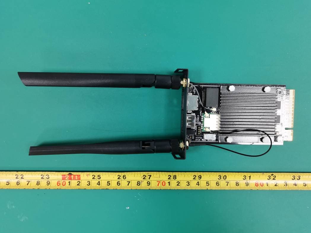
Click to zoom
Application Details
- Equipment Class
- DSS - Part 15 Spread Spectrum Transmitter
- Date of Grant
- Feb 23, 2021
- Application Purpose
- Original Equipment
- Date of Application
- Feb 23, 2021
- Equipment Note
- Wireless Presentation System
- Frequency Range
- 2402.00000000 - 2480.00000000
- Company
- Winner Wave Limited
- Country
- Hong Kong
Documents & Files
Document Text
Text extracted from the exhibit documents filed with the FCC. Open a document above to read the original.
Users Manual
Operating Instructions Basic Guide Wireless Presentation System Receiver Board For business use Model No. TY-SB01WP Thank you for purchasing the Panasonic product. •Please read these instructions before operating this product and retain them for future reference. •Be sure to read “Safety Precautions ” (page 2) before use. DPQXxxxxxx/X1DA0121TS0 -PB Safety Precautions 2 Part Names 4 Transmitter Extension Method (Pairing) 8 Installtion of the receiver board 5 Basic Use 6 Setting 10 Notes on Using Wireless LAN 15 Request Regarding Security 17 Specifications 19 English * PressIT is a nickname for “Wireless Presentation System”. Precautions for use 3 2English Safety Precautions WARNING: When mounting or removing this product on or from the flat panel display unit, be sure to turn the power off, and remove the power plug from the socket. Otherwise, electric shock may occur. Never attempt to disassemble or modify this product. Doing so may cause fire, electric shock or operation errors. If you sense smoke, unpleasant odour or unusual noises, immediately disconnect the power plug from the socket. Using the product in an abnormal condition may cause fire or electric shock. For mounting or removing this product on or from the flat panel display unit, ask a qualified technician or sales dealer. Installing the product improperly may cause a malfunction or electric shock. •If you terminate the use of the product, ask a professional to remove it promptly. Use the product 15 cm or more away from a location where a cardiac pacemaker is embedded. Radio waves may affect the operation of the pacemaker. Do not use the product in an airplane. The operational safety may be impaired. Do not use the product near an automatic door, fire alarm or other automatic control devices. Radio waves from this product may affect automatic control devices, which may cause an operational error, resulting in an accident. Do not use the product in hospital or a location with medical equipment. Radio waves from this product may affect medical equipment, which may cause an operational error, resulting in an accident. Do not wet the product. Doing so may cause a fire or electric shock. CAUTION: Do not place the product at a high-temperature location, humid or dusty location, or location subject to oil smoke or steam (such as a cooking table and humidifier). Doing so may cause a fire or electric shock. Do not place the product in locations subject to direct sunlight or extremely high temperature. •The internal parts may be damaged, or fire may occur. 3English Precautions for use This product is a Wireless Presentation System Receiver Board used by being attached to a Panasonic display. Do not touch this product directly by hand. •Static electricity may occur, destroying the components. Static electricity is also generated from clothing or human body. Let the static electricity escape by touching metallic objects such as a steel cabinet beforehand. The illustrations and figures in this manual are for explanatory purposes and may differ from the actual product. Details of usage For details of usage, read “Operating Instructions - Functional Manual”. Download the “Operating Instructions - Functional Manual” from the following URL. https://panasonic.net/cns/prodisplays/wps2/ For detailed usage of a display supporting this product, read the operating instructions of the display. 4English Part Names 1 Antenna ▼ Connection terminals / Controls 2 FUNCTION button Used to save a pairing file to the USB memory. 3 LAN terminal (RJ45) Connects to the network to change the settings of the product. 4 USB terminal (Type-A) Connects the transmitter or USB memory when pairing devices. Use this by connecting an HID device (mouse, touch module). 5 FUNCTION LED Displays the pairing status. 6 Power Indicator Displays the power supply status, and connection statuses of LAN and USB. 7 Reset button Restores the product to the factory default state. Reset operation starts when the reset button is pressed for 5 seconds or more. 1 ▼ Connection terminals / Controls 234 5 67 5English Installtion of the receiver board The installation instruction below is based on the flat panel display SQ1 series as an example. For attaching or removing this product to or from the flat panel display unit, it is recommended to ask a qualified technician or sales dealer. A malfunction may occur due to static electricity, etc. Consult the sales dealer. Follow the steps below. Note •Be sure to turn off the display unit and connected devices, remove the power plug from the socket, and disconnect the cables from the display. • When attaching/removing the receiver board, do not allow the metal to damage the back cover or display label. 1 Remove the 2 screws, and then remove the slot cover or receiver board from the display unit. To remove the receiver board, hold the handle of the receiver board and pull it out slowly in the arrow direction. 2 Insert the receiver board to the main unit slot, and tighten the 2 screws. Fix the receiver board with the 2 screws removed in step 1. ● Tightening torque guideline: 0.5 N·m or less Note •When replacing another receiver board with this product, the customer shall keep the replaced receiver board for future repair or servicing. 6English Basic Use Receiver board 1 Turn on the display. 2 Switch the input of the display to [SLOT]. 3 Pair the receiver board and the transmitter. (when connecting for the first time, see page 8) 4 When the standby screen appears on the display, preparation of the receiver board is complete. Standby screen Transmitter 1 Connect the USB terminal and HDMI input terminal of the transmitter to the image output device. •For power supply to the transmitter, 5 V/0.9 A power supply is necessary. HDMI input terminal TY-WPBC1 USB terminal TY-WPB1 For TY-WPBC1, connect the USB terminal (Type-C) to an image output device that supports the DisplayPort ALT Mode. 7English 2 Main LED changes from red blinking (connecting) to white illu…
Text truncated - open the document above for the full version.
Cover Letter(s)
WinnerWaveLimited ADD:Unit1615PeninsulaTower,538CastlePeakRoad,LaiChiKok,Kowloon,Hong Kong Email:[email protected] Tel:+886-2-82269979 FCCConfidentialAuthorization Date:2021-01-05 FEDERALCOMMUNICATIONSCOMMISSIONS AuthorizationandEvaluationDivision 7435OaklandMillsRoad Columbia,MD21046 Subject:ConfidentialityRequestregardingapplicationforcertificationof FCCID:2ADFSTYSB01WP InaccordancewithSections0.457and0.459oftheCommission’sRules,WinnerWave Limitedherebyrequestslong-termconfidentialtreatmentofinformationaccompanying thisapplicationasoutlinedbelow: BlockDiagram Schematics OperationDescription Theabovematerialscontainproprietaryandconfidentialinformationnotcustomarily releasedtothepublic.Thepublicdisclosureofthesematerialsprovidesunjustified benefitstoitscompetitorsinthemarket. SincerelyYours, Signature: StanChen Title:ProductDirector
Cover Letter(s)
Winner Wave Limited ADD: Unit 1615 Peninsula Tower,538 Castle Peak Road,Lai Chi Kok,Kowloon,Hong Kong Email: [email protected] Tel:+886-2- 82269979 Modular Approval L etter Date: 2021-01-05 FEDERAL COMMUNICATIONS COMMISSIONS Authorization and Evaluation Division 7435 Oakland Mills Road Columbia, MD 21046 Dear Application Examiner, We, Winner Wave Limited is submitting this application for certification of product named as Wireless Presentation System, Model Numbers: TY-SB01WP (FCC ID: 2ADFSTYSB01WP). It is seeking modular approval. The radio meets the requirements for modular approval as detailed in FCC 15.212. Compliance to each of the requirements is described below: 1. “The modular transmitter must have its own RF shielding.” Yes, it is fulfilled. The radio portion of the module has its own RF shielding. The shielding is installed at the factory. Please see the EUT photos. 2. “The modular transmitter must have buffered modulation/data inputs.” Yes, it is fulfilled. The EUT has buffered data inputs to insure compliance with Part 15 requirements under conditions of excessive data rates or over modulation. Please see the Schematics exhibit. 3. “The modular transmitter must have its own power supply regulation.” Yes, it is fulfilled. The EUT has its own power supply regulation to insure compliance. 4. “The modular transmitter must comply with the antenna requirements of Section 15.203 and 15.204(c).” Yes. The EUT has two PCB FR-4 antenna design. One is 5G Wi-Fi antenna 1, the other is Bluetooth/BLE antenna & 5G Wi-Fi antenna 2. 5. “The modular transmitter must be tested in a stand-alone configuration.” Yes, it is fulfilled. The EUT was tested in a stand-alone configuration. 6. “The modular transmitter must be labeled with its own FCC ID number.” Yes, it is fulfilled. The module will be labeled with its own FCC ID number. Please see FCC ID label & location exhibit. 7. “The modular transmitter must comply with any specific rule or operating requirements applicable to the transmitter and the manufacturer must provide adequate instructions along with the module to explain any such requirements.” Yes, it is fulfilled. The necessary explanation to be complied with this requirement is contained in the user manual, and please refer to the User manual. 8. “The modular transmitter must comply with any applicable RF exposure requirements.” Yes, the module is intended to use in distance more that 20cm. FCC RF exposure requirement satisfied with 47CFR §2.1091. Please contact me if you have additional questions. Your attention to this matter is greatly appreciated. Sincerely Yours, Signature: Stan Chen Title: Product Director
External Photos
Bay Area Compliance Laboratories Corp. (Shenzhen) Project No.: RSZ201221004-RF Page 1 of 2 EXHIBIT B - EUT EXTERNAL PHOTOGRAPHS Bay Area Compliance Laboratories Corp. (Shenzhen) Project No.: RSZ201221004-RF Page 2 of 2
ID Label/Location Info
Bay Area Compliance Laboratories Corp. (Shenzhen) Project No.: RSZ201221004-RF EXHIBIT A - FCC ID LABEL AND LOCATION FCC ID Label FCC ID Label Location Information The label shown shall be permanently affixed at a conspicuous location on the device and be readily visible to the user at the time purchase (Labeling requirements per 2.925)
Internal Photos
Bay Area Compliance Laboratories Corp. (Shenzhen) Project No.: RSZ201221004-RF Page 1 of 3 EXHIBIT C - EUT INTERNAL PHOTOGRAPHS 5G WIFI Antenna 1 BT/BLE Antenna 5G WIFI Antenna 2 Bay Area Compliance Laboratories Corp. (Shenzhen) Project No.: RSZ201221004-RF Page 2 of 3 Bay Area Compliance Laboratories Corp. (Shenzhen) Project No.: RSZ201221004-RF Page 3 of 3
RF Exposure Info
Bay Area Compliance Laboratories Corp. (Shenzhen) Report No.: RSZ201221004-00A FCC Part 15.247 Page 10 of 58 FCC §15.247 (i) & §2.1091- MAXIMUM PERMISSIBLE EXPOSURE (MPE) Applicable Standard According to subpart 15.247 (i) and subpart 2.1091 systems operating under the provisions of this section shall be operated in a manner that ensures the public is not exposed to RF energy level in excess of the communication guidelines. Limits for General Population/Uncontrolled Exposure Limits for General Population/Uncontrolled Exposure Frequency Range (MHz) Electric Field Strength (V/m) Magnetic Field Strength (A/m) Power Density (mW/cm 2 ) Averaging Time (Minutes) 0.3-1.34 614 1.63 *(100) 30 1.34-30 824/f 2.19/f *(180/f 2 ) 30 30-300 27.5 0.073 0.2 30 300-1500 / / f/1500 30 1500-100,000 / / 1.0 30 f = frequency in MHz * = Plane-wave equivalent power density Result Calculated Formulary: Predication of MPE limit at a given distance S = 2 4R PG π S = power density (in appropriate units, e.g. mW/cm2) P = power input to the antenna (in appropriate units, e.g., mW). G = power gain of the antenna in the direction of interest relative to an isotropic radiator, the power gain factor, is normally numeric gain. R = distance to the center of radiation of the antenna (appropriate units, e.g., cm) Bay Area Compliance Laboratories Corp. (Shenzhen) Report No.: RSZ201221004-00A FCC Part 15.247 Page 11 of 58 Mode Frequency (MHz) Antenna Gain Max Conducted Power Evaluation Distance (cm) Power Density (mW/cm 2 ) MPE Limit (mW/cm 2 ) (dBi) (numeric) (dBm) (mW) BT 2402-2480 3.0 2.0 3.2 2.09 20 0.0008 1 BLE 2402-2480 3.0 2.0 2.3 1.70 20 0.0007 1 5GHz wifi 5150-5250 5.0 3.16 13 20 20 0.013 1 5725-5850 5.0 3.16 13 20 20 0.013 1 Note: 1) To maintain compliance with the FCC’s RF exposure guidelines, place the equipment at least 20cm from nearby persons. 2) Bluetooth and 5GHz Wi-Fi can transmit simultaneously for this device. 3) Simultaneous transmitting consideration: The ratio=MPE bluetooth /limit+MPE wifi /limit=0.0008+0.013=0.0138<1.0, So, compliance with simultaneous exposure requirement. Result: Pass
Test Report
Note: This report may contain data that are not covered by the A2LA accreditation and are marked with an asterisk “★”. BACL is not responsible for the authenticity of any test data provided by the applicant. Data included from the applicant that may affect test results are marked with an asterisk ’*’. Customer model name, addresses, names, trademarks etc. are not considered data. This report cannot be reproduced except in full, without prior written approval of the Company. Unless otherwise stated the results shown in this test report refer only to the sample(s) tested. This report is valid only with a valid digital signature. The digital signature may be available only under the Adobe software above version 7.0. FCC PART 15.247 TEST REPORT For Winner Wave Limited Unit 1615 Peninsula Tower,538 Castle Peak Road Lai Chi Kok Kowloon Hong Kong FCC ID: 2ADFSTYSB01WP Report Type: Original Report Product Type: Wireless Presentation System Re port Number: RSZ201221004-00A Re port Date: 2021-02-04 Reviewed B y: Jacob Kong RF Engineer Prepared By: Bay Area Compliance Laboratories Corp. (Shenzhen) 6/F., West Wing, Third Phase of Wanli Industrial Building, Shihua Road, Futian Free Trade Zone, Shenzhen, Guangdong, China Tel: +86-755-33320018 Fax: +86-755-33320008 www.baclcorp.com.cn Bay Area Compliance Laboratories Corp. (Shenzhen) Report No.: RSZ201221004-00A FCC Part 15.247 Page 2 of 58 TABLE OF CONTENTS GENERAL INFORMATION ....................................................................................................................................... 4 PRODUCT DESCRIPTION FOR EQUIPMENT UNDER TEST (EUT) ..................................................................................... 4 OBJECTIVE ................................................................................................................................................................... 4 TEST METHODOLOGY .................................................................................................................................................. 4 MEASUREMENT UNCERTAINTY .................................................................................................................................... 5 TEST FACILITY ............................................................................................................................................................. 5 SYSTEM TEST CONFIGURATION .......................................................................................................................... 6 DESCRIPTION OF TEST CONFIGURATION ...................................................................................................................... 6 EUT EXERCISE SOFTWARE .......................................................................................................................................... 6 SPECIAL ACCESSORIES ................................................................................................................................................. 6 EQUIPMENT MODIFICATIONS ....................................................................................................................................... 6 SUPPORT EQUIPMENT LIST AND DETAILS .................................................................................................................... 6 EXTERNAL I/O CABLE .................................................................................................................................................. 6 BLOCK DIAGRAM OF TEST SETUP ................................................................................................................................ 7 SUMMARY OF TEST RESULTS ............................................................................................................................... 8 TEST EQUIPMENT LIST ........................................................................................................................................... 9 FCC §15.247 (i) & §2.1091- MAXIMUM PERMISSIBLE EXPOSURE (MPE) ........................................................ 10 APPLICABLE STANDARD ............................................................................................................................................ 10 RESULT ...................................................................................................................................................................... 10 FCC §15.203 – ANTENNA REQUIREMENT .......................................................................................................... 12 APPLICABLE STANDARD ............................................................................................................................................ 12 ANTENNA CONNECTOR CONSTRUCTION .................................................................................................................... 12 FCC §15.207 (a) – AC LINE CONDUCTED EMISSIONS ..................................................................................... 13 APPLICABLE STANDARD ............................................................................................................................................ 13 EUT SETUP ................................................................................................................................................................ 13 EMI TEST RECEIVER SETUP ....................................................................................................................................... 13 TEST PROCEDURE ...................................................................................................................................................... 13 CORRECTED FACTOR & MARGIN CALCULATION ....................................................................................................... 14 TEST DATA .....................................................................................................................................…
Text truncated - open the document above for the full version.
Test Setup Photos
Bay Area Compliance Laboratories Corp. (Shenzhen) Project No.: RSZ201221004-RF Page 1 of 2 EXHIBIT D - TEST SETUP PHOTOGRAPHS Conducted Emissions - Front View Conducted Emissions - Side View Bay Area Compliance Laboratories Corp. (Shenzhen) Project No.: RSZ201221004-RF Page 2 of 2 Radiated Emissions – Front View (Below 1 GHz) Radiated Emissions View (Above 1 GHz)
Contact Information
Applicant
Rock Huang(Technical Manager)
Test Firm
Bay Area Compliance Laboratories Corp. (Shenzhen)Well Wang
[email protected]+86 (0) 755 33320018
Technical Specifications
| # | Rule Parts | Frequency Range | Power Output |
|---|---|---|---|
| 1 | 15C | 2.40 GHz - 2.48 GHz | 2.00 mW |
Other Applications from Winner Wave Limited
2ADFS-POCKET-R-1DPocket
Jan 28, 2026Equipment Class
NII - Unlicensed National Information Infrastructure TX2ADFS-CAMCAST-CT1
Dec 23, 2025CamCast
Equipment Class
NII - Unlicensed National Information Infrastructure TX2ADFS-MINIPOCKET-H1
Dec 02, 2024Mini Pocket
Equipment Class
NII - Unlicensed National Information Infrastructure TX2ADFS-ULTRA-U2
Oct 10, 2024Ultra
Equipment Class
DTS - Digital Transmission System2ADFS-POCKET-RC-1Pocket
Sep 05, 2024Equipment Class
NII - Unlicensed National Information Infrastructure TX