2ADG2ZW-6400HSelf-contained Security Alarm System
UHS Pty Ltd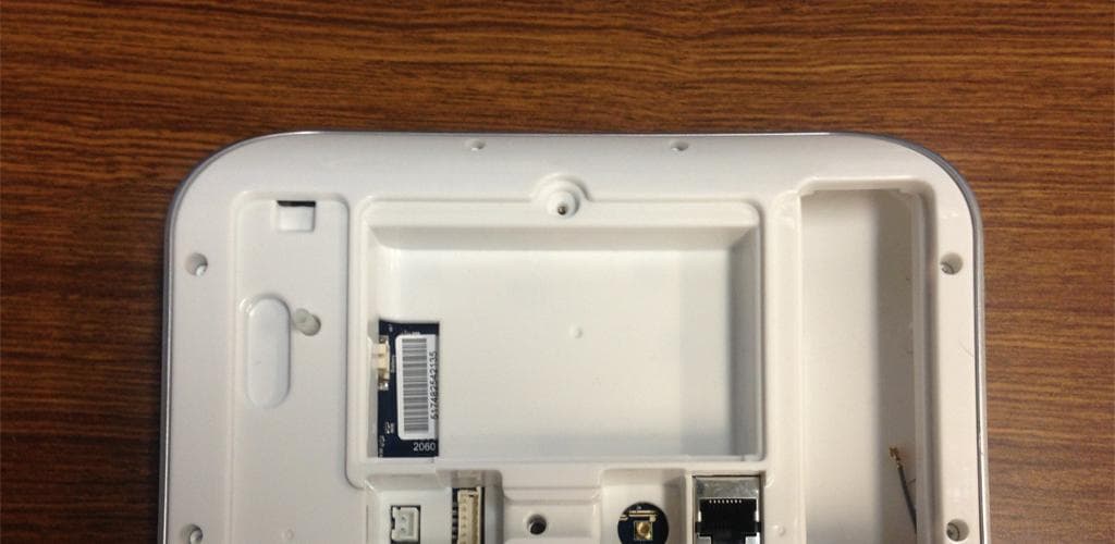
Click to zoom
Application Details
- Equipment Class
- DXX - Part 15 Low Power Communication Device Transmitter
- Date of Grant
- Nov 13, 2014
- Application Purpose
- Original Equipment
- Date of Application
- Nov 12, 2014
- Equipment Note
- Self-contained Security Alarm System
- Frequency Range
- 908.40000000 - 908.40000000
- Company
- UHS Pty Ltd
- Country
- Australia
Documents & Files
Document Text
Text extracted from the exhibit documents filed with the FCC. Open a document above to read the original.
Users Manual
USERMANUAL ‐ 2 ‐ ‐ 3 ‐ Contents Welcome!........................................................4 1. Basic Features .............................................8 2. Add Users & Key Fobs ...............................15 3. Smartphone App .......................................20 4. Customize Your ZeroWire .........................25 Maintenance.................................................33 Reference......................................................36 ‐ 4 ‐ Welcome! Thank you for purchasing ZeroWire! Your ZeroWire is set up and ready to use. The voice guide will walk you through how to use various features and provide updates on your system. 1 Arming and Disarming 2 Add users & key fobs 3 Smartphone App 4 Customize your system Read through this guide to get the most out of your system. The level of security ZeroWire can provide is dependent on: The quantity, quality, and placement of security devices attached to this security system; And the regular use of features including performing a weekly test. ‐ 5 ‐ Your New Security System Your system should be set up by a professional security installer. These parts should be provided: Quick Reference Guide User Manual (this document) ZW‐6400 ZeroWire with Wall Bracket Backup Battery Pack (installed inside ZeroWire) 9VDC Power Pack Optional Parts ZW‐ANT3M Extension Antenna ZW‐DS01 Desk Stand ZW‐HSPA Cellular Modem User Manual Quick Reference Guide ‐ 6 ‐ Front of ZeroWire Key Colour Description ALARM Red System is in alarm. Enter your PIN code then ENTER to turn off the alarm. Press the STATUS key for more info. Yellow System is armed in Stay mode. STAY Not lit System is disarmed if Away is also not lit. Press the STAY key to arm in Stay mode. Green System is normal. Yellow Non‐urgent system conditions present. Press the STATUS key to hear system conditions. STATUS Red Urgent system conditions present. Press the STATUS key to hear system conditions. If you are unable to fix the issue, contact your service provider for help. Red System is armed in Away mode. AWAY Not lit System is disarmed if Stay is also not lit. Press the AWAY key to arm in Away mode. Key Colour Description Green (steady) All sensors are ready and the system can be armed in Away or Stay mode. Green (flashing) Some sensors are unsealed but system is force‐armable. If these sensors are not sealed by the end of the exit time the system will go into alarm. READY Not lit System cannot be armed, press the STATUS key for more info BYPASS Press the BYPASS key if you wish to isolate (ignore) a sensor. Bypassed sensors will not be active when you arm the system in Stay or Away modes. CHIME Press the CHIME key to select which sensors will make a doorbell sound on the ZeroWire when they are tripped. HISTORY Press the HISTORY key to listen for alarm and event history. FIRE MEDICAL POLICE Feature must be enabled by your security provider. Check what response will be provided. Hold down the key to send a message to a central monitoring centre. Enter your PIN code then ENTER to turn off a SOS alarm. ‐ 7 ‐ Back of ZeroWire ‐ 8 ‐ 1. Basic Features Arm your system in Away Mode Protect your property using Away Mode when you are leaving the premises. Normally all sensors must be secure before you can arm in Away Mode, this will be indicated by the Ready Light being lit a solid green. If the Ready Light is flashing green then “forced arming” is enabled. This means some sensors are not secure but you can still arm your security system. Read more about the Forced Arming Feature on page 9. If the Status Key is not green press the Status Key to hear what sensors are not secured. You may arm your system using your user PIN code: 1. READY STATUS Check ready key is green Check status key is green 2. AWAY Select the Away Mode 3. 4. Leave the premises To silence the Exit Delay beeping, press the Away Key again and the beeping will stop. This can also be performed from the UltraConnect app. ENTER EXIT DELAY BEEPS USER PIN CODE ‐ 9 ‐ If your service provider has enabled the quick arm feature, you can simply touch the Away key: 5. READY STATUS Check ready key is green Check status key is green 6. AWAY Select the Away Mode 7. Leave the premises Forced Arming Feature Normally all sensors must be secure before you can arm your security system. For example, a home with a door sensor on the front door. When forced arming is NOT enabled, you would have to close the door before being allowed to arm the system. When force arming is enabled, you can arm your system with the door opened, and the door will automatically be protected after it is fully closed as you leave. If your service provider has enabled the “forced arming” feature, you will be able to arm your security system even if pre‐selected sensors are not secure. The Ready Light will flash green to indicate this feature is available. Press Status key to hear which sensors are not secure. Check with your installer to confirm how Forced Arming has been set up for your system: Option 1: At the end of the exit delay, sensors that are not secured will automatically by bypassed. If they later become secured, the bypass will be removed and they will become part of the active security system until the system is disarmed. Option 2: At the end of the exit delay, sensors that are not secured will trigger an entry delay or go into alarm. EXIT DELAY BEEPS ‐ 10 ‐ Arm your system in Stay Mode Use Stay Mode when you are staying in the premises and you want the perimeter protected whilst allowing you to move around inside without setting the alarm off. This gives you peace of mind even when you are at home. For example, Stay Mode is often used at night to arm sensors around the perimeter of your home and bypass all internal movement sensors. This will allow you to move around inside your home without causing the system to sound an alarm. Perimeter sensors will still be active to detect intruders. The security of your home in Stay mode is dependant on…
Text truncated - open the document above for the full version.
External Photos
Model: 206024 ZeroWire 750mA@9V Made in Mexico 615355280484 FCC ID: 2ADG2ZW-6400H Contains FCC ID: W7OMRF24WG0MAMB
ID Label/Location Info
FCC ID : 2ADG2ZW-6400H Label and Location EUT rear view
Internal Photos
FCC ID : 2ADG2ZW-6400H Internal Photographs EUT with rear covers removed Internal top view FCC ID : 2ADG2ZW-6400H Internal Photographs Internal bottom view RF Circuit Locations
Test Report
EMC Services - Consulting engineers in EMC, EMR, RF hazards and site surveys International - Tel 61-2-9975 4555, Fax 61-2-9876 2796, E-Mail [email protected] EMC Services Pty Ltd ABN 42 072 235 306 12/8 Tilley Lane Frenchs Forest NSW 2086 Australia Tel: +61 2 9975 4555 Fax: +61 2 9876 2796 Web: www.emc.net.au Report No. 140805-2a Compliance Testing Report of the “Zero Wire Alarm System” to FCC Part 15 (B) Class B (ANSI C63.4:2003) and FCC part 15 (C) Para 15.249 (ANSI C63.4:2003) for UHS Systems Pty Ltd Prepared by: __________________ Reviewed by: _______________ Michael Matevski Geoff Garrett Date: 13 th November 2014 This report may not be reproduced whole or in part without the permission of EMC Services Pty Ltd Report No 140805-2a Page 2 of 18 This report may not be reproduced in whole or in part without the permission of EMC Services Pty Ltd Contents 1. Client Information ............................................................................................................................. 3 2. Equipment Under Test (EUT)............................................................................................................ 3 2.1 Identification of EUT ................................................................................................................. 3 2.2 Accessory Equipment ............................................................................................................... 3 2.3 Auxiliary Equipment .................................................................................................................. 3 2.4 Operating Conditions of EUT .................................................................................................... 3 3. Test Specifications ........................................................................................................................... 4 3.1 Standard Selected .................................................................................................................... 4 3.2 Changes from the Selected Standard ....................................................................................... 4 3.3 Test Facility .............................................................................................................................. 4 3.4 Test Equipment......................................................................................................................... 5 4. Test Summary .................................................................................................................................. 6 4.1 Emissions (unintentional) FCC Part 15 (B) Class B, (see Figures 1a to 3b) .............................. 6 4.2 Radiated Emissions (intentional) to FCC part 15 (C) Para 15.249 ............................................. 6 5. Modifications : None ........................................................................................................................ 6 6. Test Results ..................................................................................................................................... 7 6.1 Test Conditions ......................................................................................................................... 7 6.2 Conducted Emissions ............................................................................................................... 7 6.3 Radiated Emissions .................................................................................................................. 7 7. Measurement Uncertainty ................................................................................................................. 7 8. Test Plots ......................................................................................................................................... 7 9. Test Facility .................................................................................................................................... 12 10. Photographs ............................................................................................................................... 13 11. Appendices ................................................................................................................................. 17 Report No 140805-2a Page 3 of 18 This report may not be reproduced in whole or in part without the permission of EMC Services Pty Ltd 1. Client Information Company: UHS Pty Ltd Suite 203, 5-13 Rosebery Avenue, Rosebery, NSW 2018, Australia Tel: +61 (0) 2 9663 2299 Web: www.uhssystems.com 2. Equipment Under Test (EUT) 2.1 Identification of EUT Equipment Description: A security alarm system Model: Zero Wire Module Number: ZW-6400H Make: UHS Supply: 16 VAC 60 Hz (through an AC Adapter) 2.2 Accessory Equipment AC Adapter: Make: ZB, Model Number: ZB-A090020A-J Supply Rating: 120 VAC, 60 Hz 2.3 Auxiliary Equipment Ethernet Switch: Make - Linksys, Model - SD205 2.4 Operating Conditions of EUT The tests were performed with the EUT powered by the AC Adapter. The EUT was orientated manually during the test for maximum emissions. The internal GSM and short range wireless modules were operational during testing. Report No 140805-2a Page 4 of 18 This report may not be reproduced in whole or in part without the permission of EMC Services Pty Ltd 3. Test Specifications 3.1 Standard Selected ANSI C63.4:2003 was selected to demonstrate compliance with the applicable EMC requirements of FCC Part 15 (B) Class B and FCC Part 15 (C) Para 15.249, as the EUT is within the scope of this standard, and ANSI C63.4 is the preferred method of compliance with 47CFR Part 15 rules. 3.2 Changes from the Selected Standard None 3.3 Test Facility All EMI tests reported within this document were performed by EMC Services Pty Ltd measurement facility located at the following location: Laboratory and Open Area Test Site: Hampton Grove Rydal Road Hampton, NSW, Australia, …
Text truncated - open the document above for the full version.
Test Setup Photos
FCC ID : 2ADG2ZW-6400H External Photographs EUT front view EUT rear view FCC ID : 2ADG1ZW-6400H Model : ZeroWire External Photographs AC Adapter
Contact Information
Applicant
Jeff Baines(Principal Engineer)
Test Firm
EMC Services Pty LtdGeoffrey Garrett
Technical Specifications
| # | Rule Parts | Frequency Range | Power Output |
|---|---|---|---|
| 1 | 15C | 908.4 MHz - 908.4 MHz | - |