2ADHF-INTELPAGEPaging Transmitter
SPOK Aus Pty. Ltd.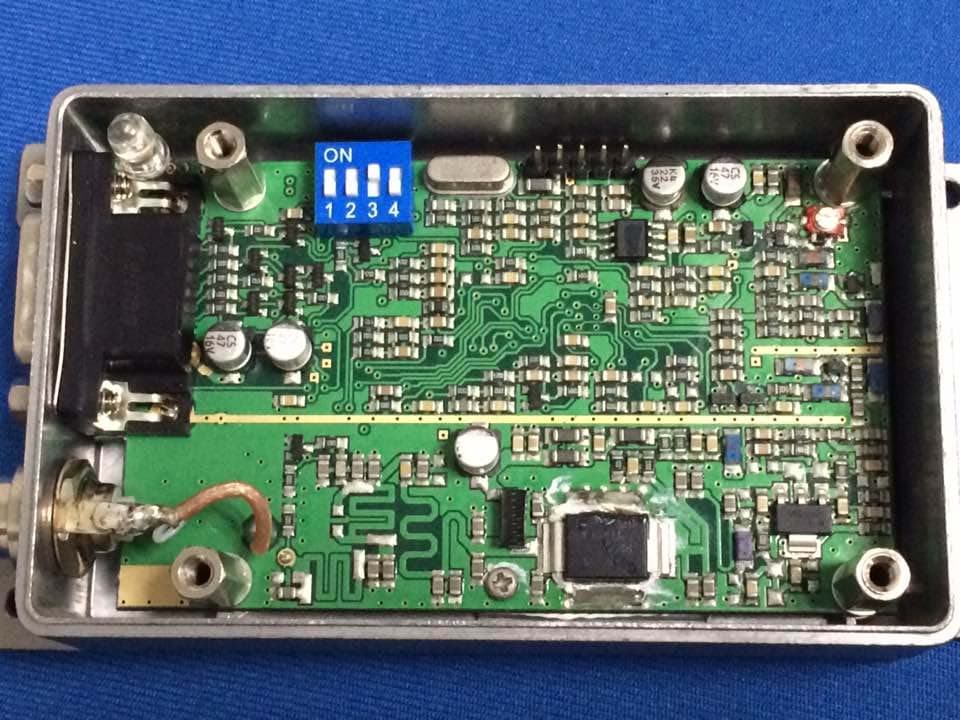
Click to zoom
Application Details
- Equipment Class
- TNB - Licensed Non-Broadcast Station Transmitter
- Date of Grant
- Nov 17, 2014
- Application Purpose
- Original Equipment
- Date of Application
- Nov 16, 2014
- Equipment Note
- Paging Transmitter
- Frequency Range
- 450.00000000 - 470.00000000
- Company
- SPOK Aus Pty. Ltd.
- Country
- Australia
Documents & Files
Document Text
Text extracted from the exhibit documents filed with the FCC. Open a document above to read the original.
Users Manual
Installation & Configuration Guide for Intelpage IP Amcom Software, Inc. Copyright Intelpage IP v2.12 Firmware Document Version 1.0 Last Saved Date: October 10, 2013 Copyright 2003-2013 Amcom Software, Inc. All Rights Reserved. Information in this document is subject to change without notice. The software described in this document is furnished under one or more Program/Product License Agreements. The software may be used or copied only in accordance with the terms of those agreements. No part of this publication may be reproduced, stored in a retrieval system, or transmitted by any means electronic or mechanical, including photocopying and recording for any purpose without the written permission of Amcom Software, Inc. Amcom Software, Inc. 10400 Yellow Circle Drive Suite 100 Eden Prairie, MN 55343 USA Trademarks Microsoft and Windows are trademarks of Microsoft Corporation. Other brands and their products are trademarks or registered trademarks of their respective holders and should be noted as such. Installation & Configuration Guide for Intelpage IP Contents iii Contents Intelpage IP 1 Intelpage IP ......................................................................................................................... 1 Compliance Information ..................................................................................................... 1 Safety and General Information .......................................................................................... 3 About the Intelpage IP 4 About the Intelpage IP ........................................................................................................ 4 Intelpage IP Kit .................................................................................................... 4 LEDs and Connectors ......................................................................................................... 5 LED Indicators ..................................................................................................... 6 Connectors ............................................................................................................ 6 LCD Display (High Power Version Only) ........................................................... 7 Installation 8 Installation .......................................................................................................................... 8 Rack Version ...................................................................................................................... 8 Desktop Version ................................................................................................................. 9 Configuration 10 Configuration .................................................................................................................... 10 Connecting ........................................................................................................................ 10 Logging In ........................................................................................................................ 13 User Interface Fields ......................................................................................................... 14 Home .................................................................................................................. 14 Pagers ................................................................................................................. 15 Network Settings ................................................................................................ 16 Serial Port Settings ............................................................................................. 17 Transmitter Settings............................................................................................ 18 Protocol .............................................................................................................. 19 Pocsag ................................................................................................................. 21 Password ............................................................................................................. 22 IP Access List ..................................................................................................... 23 Site Survey ......................................................................................................... 24 Status .................................................................................................................. 25 Licensing ............................................................................................................ 26 Configuration Examples 28 Configuration Examples ................................................................................................... 28 Setting up Dial-in TAP to Intelpage IP from Messenger .................................................. 28 Intelpage IP 2 Installation & Configuration Guide for Intelpage IP Appendix 30 Appendix .......................................................................................................................... 30 Configuring Network Settings Through the Terminal Interface ....................................... 30 Transmitters ...................................................................................................................... 34 Installing Multiple Transmitters and Aerials ...................................................... 34 VSWR ................................................................................................................ 34 Types of Antennas ............................................................................................................ 35 Technical Specifications ................................................................................................... 36 General ............................................................................................................... 36 Desktop Version…
Text truncated - open the document above for the full version.
Cover Letter(s)
Data Efficiency, Letter of Compliance TO: MiCOM Labs ATTENTION:FCC Equipment Authorization Division This letter is to confirm that the highpower intelpage is capable of transmiting 9600bps in 12.5KHz of channel BW, thereby meeting the data efficiencyr requirements of Title 47, chapter I, Sub Chapter D, section 90.203(j)(5) which states: Applicant Company name: SPOK Aus Pty. Ltd. Grantee code: 2ADHF Contact name: Clinton Cambridge Address: 130 Main Street, Osborne Park, Perth 6017, Western Australia, Australia Telephone No: +61 8 6240 0000 Fax No: +61 8 6240 0000 Email: [email protected] FCC ID: 2ADHF- INTELPAGE Model Number: Intelpage High Power Date:2014.11.18 Signature:
Cover Letter(s)
SPOK Aus Pty. Ltd. 130 Main Street, Osborne Park, Perth 6017 Western Australia, Australia Ph: +61 8 6240 0000 Email: [email protected] Novermber 18, 2014 Office of Engineering and Technology Laboratory Division Equipment Authorization Branch FCC Laboratory7435 Oakland Mills Rd. Columbia, MD 21046 Re: Extended Frequency Justification on FCC ID: 2ADHF- INTELPAGE To whom it may concern: The Intelpage High Power 25W was designed to operate in the frequency band 450-470 MHz. To aid equipment authorization in other services/countries which accept the United States FCC Grant for certification, but which are not governed by the FCC, SPOK is requesting that the FCC list the frequencies 450-470 MHz under FCC Rule Parts 90 on the FCC Grant. This is being requested to facilitate the requirements of agencies covered under NTIA spectrum usage. Government agencies complying with the NTIA instead of the FCC and other countries must purchase their equipment from private industry manufacturers who are governed under the FCC rules. This conflict in spectrum allocation detracts from the options available to the government agencies for commercial off-the-shelf equipment which meets their required specifications such as the requirements stated in the Department of Interior’s narrowband Digital Radio Contract. Per the FCC’s KDB634817 guidance, “as an alternative to listing the exact frequencies, we acknowledge that it is a violation of the FCC Rules if this device operates on unauthorized frequencies.” Also, per FCC Rules Parts 90.203(e) and (g), programming of transmitter frequencies can only be performed by the manufacturer or authorized service and maintenance personnel. Frequency Range (MHz) Part 90 Other 450-454 x 454-456 x 456-452.5375 x 462.5375-462.7375 x 462.7375-467.5375 x 467.5375-467.7375 x 467.7375-470 x Sincerely, Clinton Cambridge Manager SPOK Aus Pty. Ltd. Email: [email protected]
Cover Letter(s)
< SPOK Aus Pty. Ltd. > Office of Engineering Technology Federal Communications Commission 7435 Oakland Mills Road Columbia, MD 21046 Date: 2014.10.29 Subject; Request for Confidentiality FCC ID: 2ADHF-INTELPAGE To Whom It May Concern, Pursuant to the provisions of Sections 0.457 and 0.459 of Commission's rules (47CFR0.457, 0.459), we are requesting the Commission to withhold the following attachment(s) as confidential document from public disclosure indefinitely. • Schematic Diagram • Block Diagram • Operational Description • Boom list Above mentioned document contains detailed system and equipment description are considered as proprietary information in operation of the equipment. The public disclosure of above documents might be harmful to our company and would give competitor an unfair advantage in the market. In additional to above mentioned documents, pursuant to Public Notice DA 04-1705 of the Commission' s policy, in order to comply with the marketing regulations in 47 CFT §2.803 and the importation rules in 47 CFR §2.1204, while ensuring that business sensitive information remains confidential until the actual marketing of newly authorized devices. We are requesting the commission to grant shot-term confidentiality request on the following attachment(s) for 180 days after the grant as outlined in Public Notice DA 04-1705. It is our understanding that all measurement test reports, FCC ID label format and correspondent during certification review process cannot be granted as confidential documents and those information will be available for public review once the grant of equipment authorization is issued. Sincerely, Signature: Name: Clinton Cambridge Title: Manager
External Photos
External photo
ID Label/Location Info
LABEL ARTWORK AND LOCATION Label size: L*W=40*40mm SPOK Aus Pty. Ltd. Prod. Name: Paging Transmitter Model: INTELPAGE HIGH POWER FCC ID: 2ADHF- INTELPAGE CAUTION: The antenna(s) used for this transmitter must not be co-located or operating in conjunction with any other transmitter/antenna system. The antenna should be mounted so as to maintain a distance of at least 89CM between the antenna and bystanders, when operated in a typical installation and a 4 dBi antenna. FCC ID Label Location
Internal Photos
Inside View of the EUT
RF Exposure Info
Maximum Permissible Exposure According to §1.1307, systems operating under the provisions of this section shall be operated in a manner that ensures that the public is not exposed to radio frequency energy level in excess of the Commission’s guidelines. According to §1.1310 and §2.1091 RF exposure is calculated. Limits for Maximum Permissive Exposure (MPE) f = frequency in MHz * = Plane-wave equivalent power density MPE Prediction Equation from page 18 of OET Bulletin 65, Edition 97-01 S = PG/4πR² Where: S = power density P = power input to antenna G = power gain of the antenna in the direction of interest relative to an isotropic radiator R = distance to the center of radiation of the antenna Duty cycle= 50% Maximum peak output power at antenna input terminal: 43.89 (dBm) Maximum peak output power at antenna input terminal: 24500 (mW) Predication frequency:462.775 (MHz) Antenna Gain (typical): 4 (dBi) antenna gain: 2.51 (numeric) MPE limit for uncontrolled exposure at prediction frequency: 0.31 (mW/cm2) MPE limit for uncontrolled exposure at prediction distance:89cm RF Exposure Requirements: Proposed RF exposure safety information to include in User’s Manual: CAUTION: The antenna(s) used for this transmitter must not be co-located or operating in conjunction with any other transmitter/antenna system. The antenna should be mounted so as to maintain a distance of at least 89CM between the antenna and bystanders, when operated in a typical installation and a 4 dBi antenna.
Test Report
FCC ID TEST REPORT for Paging Transmitter Model: Intelpage High Power FCC ID: 2ADHF- INTELPAGE Prepared for: SPOK Aus Pty. Ltd. 130 Main Street, Osborne Park, Perth 6017, Western Australia, Australia Prepared by: Shenzhen TCT Testing Technology Co.,Ltd 1F, Building 1, Yibaolai Industrial Park, Qiaotou Village, Fuyong Town, Baoan District, Shenzhen, Guangdong, China TEL: +86-0755-27673339 FAX: +86-0755-27673332 Report Number:TCT141009E006 Date of Test: Oct. 10-Oct. 25, 2014 Date of Report: Oct. 29, 2014 The results detailed in this test report relate only to the specific sample(s) tested. It is the Application’s responsibility to ensure that all production units are manufactured with equivalent EMC characteristics. This report is not to be reproduced except in full, without written approval from TCT Testing Technology. FCCID:2ADHF-INTELPAGE Report Number:TCT141009E006 Page 2 of 36 Table of Contents 1.0 General Details................................................................................................................................................... 3 1.1 Test Lab Details ........................................................................................................................................... 3 1.2 Applicant Details ......................................................................................................................................... 3 1.3 Description of EUT...................................................................................................................................... 4 1.4 Statement ..................................................................................................................................................... 4 1.5 Test Engineer ............................................................................................................................................... 4 2.0 Test equipments and Associated Equipment used during the test................................................................. 5 2.1 Test Equipments........................................................................................................................................... 5 2.2 AE used during the test ................................................................................................................................ 5 2.3 Test Mode .................................................................................................................................................... 6 3.0 Technical Details................................................................................................................................................ 7 3.1 Summary of test results ............................................................................................................................... 7 3.2 Test Standards .............................................................................................................................................. 7 4.0 EUT Modification.............................................................................................................................................. 7 5.0 Measurement Uncertainty(95% confidence levels, k=2)............................................................................. 7 6.0 Power Line Conducted Emission Test.............................................................................................................. 8 7.0 RF Output Power............................................................................................................................................. 12 8.0 Occupied Bandwidth & Emission Mask........................................................................................................ 13 9.0 Spurious Emissions at Antenna Terminals.................................................................................................... 22 10.0 Spurious Radiated Emissions....................................................................................................................... 28 11.0 Frequency Stability........................................................................................................................................ 31 12.0 Transmitter Frequency Behavior................................................................................................................. 33 FCCID:2ADHF-INTELPAGE Report Number:TCT141009E006 Page 3 of 36 1.0 General Details 1.1 Test Lab Details Name : Shenzhen Tongce Testing Lab Address: 1F, Leinuo Watch Building, Fuyong Town, Baoan Dist, Shenzhen, China Telephone: 13410377511 Fax: -- The test facility is recognized, certified, or accredited by the following organizations: FCC Registration Number: 572331 Shenzhen TCT Testing Technology Co., Ltd., Shenzhen EMC Laboratory: Shenzhen Tongce Testing Lab The 3m Semi-anechoic chamber has been registered and fully described in a report with the (FCC) Federal Communications Commission. The acceptance letter from the FCC is maintained in our files. Registration Number: 572331 Industry Canada (IC) The 3m Semi-anechoic chamber of Shenzhen TCT Testing Technology Co., Ltd. has been registered by Certification and Engineering Bureau of Industry Canada for radio equipment testing Registration Number IC: 10668A-1 1.2 Applicant Details Applicant: SPOK Aus Pty. Ltd. Address: 130 Main Street, Osborne Park, Perth 6017, Western Australia, Australia Telephone: 618 6240 0000 Fax: 618 6240 0000 Manufacturer: SPOK Aus Pty. Ltd. Address: 130 Main Street, Osborne Park, Perth 6017, Western Australia, Australia Telephone: 618 6240 0000 Fax: 618 6240 0000 FCCID:2ADHF-INTELPAGE Report Number:TCT141009E006 Page 4 of 36 1.3 Description of EUT Product: Paging Transmitter Model No.: Intelpage High Power Additional Model No.: N.A. Brand Name SPOK Power supply: Input: AC 100-240V, 50-60Hz Test power: AC 120V/60Hz Modulation Type: FSK Emission designator F1D Rated Power 10~25Watts Operation Frequency: From 450MHz-470MH…
Text truncated - open the document above for the full version.
Test Setup Photos
1 Conducted Emission test view Radiated Emission test view 2
Contact Information
Applicant
Clinton Cambridge
Technical Contact
Shenghen Toncce Testing LabAlan Gang
[email protected](86)13410377511
1F, Leinuo Watch Building, Fuyong Town · Shenzhen · China
Test Firm
Shenzhen Tongce Testing LabJoe Zhou
[email protected]860755-36638142
Technical Specifications
| # | Rule Parts | Frequency Range | Power Output | Emission | Tolerance |
|---|---|---|---|---|---|
| 1 | 90 | 450 MHz - 470 MHz | 24.5 W | 7K40F1D | 1.5000000000 ppm |