2ADI8-303132Mifare Module
BEIJING STRONGLINK TECHNOLOGY CO,. LTD.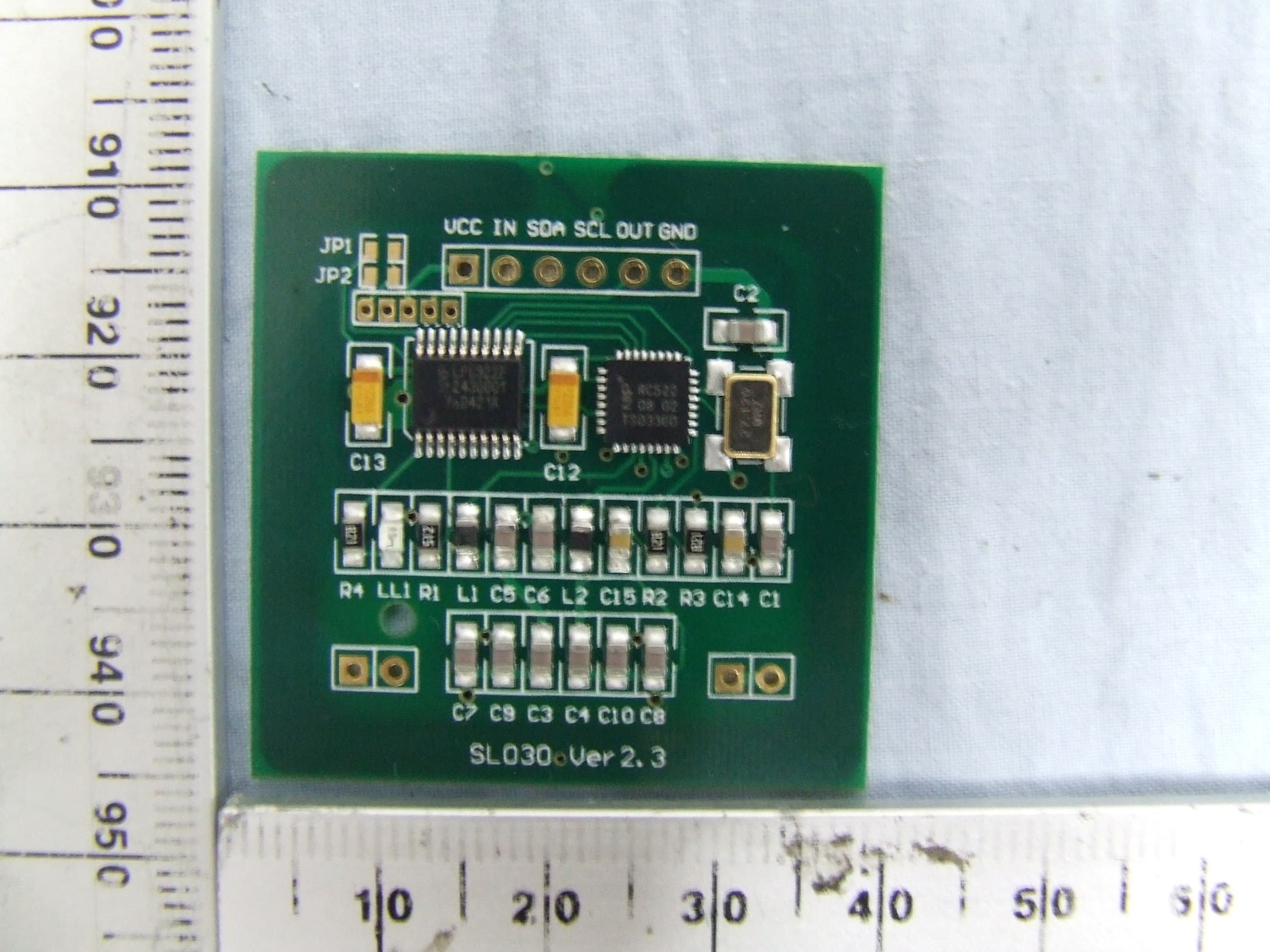
Click to zoom
Application Details
- Equipment Class
- DXX - Part 15 Low Power Communication Device Transmitter
- Date of Grant
- Dec 21, 2014
- Application Purpose
- Original Equipment
- Date of Application
- Dec 17, 2014
- Equipment Note
- Mifare Module
- Frequency Range
- 13.56000000 - 13.56000000
- Country
- China
Documents & Files
Document Text
Text extracted from the exhibit documents filed with the FCC. Open a document above to read the original.
Users Manual
RFID MODULE Mifare Reader / Writer SL030 User Manual Version 2.6 Nov 2012 StrongLink StrongLink SL030 http://www.stronglink-rfid.com 2 FCC statement This device complies with Part 15 of the FCC Rules. Operation is subject to the following two conditions: (1) This device may not cause harmful interference, and (2) This device must accept any interference received, including interference that may cause undesired operation. Please take attention that changes or modification not expressly approved by the party responsible for compliance could void the user’s authority to operate the equipment. Note: This product has been tested and found to comply with the limits for a Class B digital device, pursuant to Part 15 of the FCC Rules. These limits are designed to provide reasonable protection against harmful interference in a residential installation. This product generates, uses, and can radiate radio frequency energy and, if not installed and used in accordance with the instructions, may cause harmful interference to radio communications. However, there is no guarantee that interference will not occur in a particular installation. If this product does cause harmful interference to radio or television reception, which can be determined by turning the equipment off and on, the user is encouraged to try to correct the interference by one or more of the following measures: —Reorient or relocate the receiving antenna. —Increase the separation between the equipment and receiver. —Connect the equipment into an outlet on a circuit different from that to which the receiver is connected. —Consult the dealer or an experienced radio/TV technician for help. Important Information: When the FCC identification number is not visible when the module is installed inside another device, then the outside of the device into which the module is installed must also display a label referring to the enclosed module. This exterior label can use wording such as the following: “Contains Transmitter Module FCC ID: 2ADI8-303132” or “Contains FCC ID: 2ADI8-303132” and the information should be also contained in the devices’ user manual This is a RFID module which can read and write data from/to a tag. When a command(data) is sent to the module via its UART port, input data is bufferred in the MCU chip(LPC922). Then the data is translated and sent to RF chip(RC522) where the data is sent to the tag. When the tag responds - it send response data back which is bufferred in the RC522, then sent to LPC922 where the data is also buffered. The shielding should be made of matel material and the pitch of shielding grid should be smaller than 3cm. The shielding should cover every direction and the module is installed in the center. The distance between the module and the shielding should be more than 1cm. Pay attention, there should be no shielding above the top of the module and the size of the shieding vacancy should be at least the same size as the module's.Otherwise the RF signal can not reach the tag. This module is powered via the VCC line soldered on the pin VCC of the interface port. The voltage range should be according to <User Manual>. And power supply's GND should be conneted with pin GND. The power supply should have short-circuit protection. StrongLink SL030 http://www.stronglink-rfid.com 3 CONTENT 1. MAIN FEATURES ............................................................................... 4 2. PINNING INFORMATION ................................................................. 5 3. DEVICE OPERATION ......................................................................... 6 3-1. Clock and Data Transitions: ................................................................. 6 3-2. Start Condition ..................................................................................... 6 3-3. Stop Condition ..................................................................................... 6 3-4. Acknowledge ....................................................................................... 6 3-5. Busy State ............................................................................................ 7 3-6. Device Addressing ............................................................................... 7 3-7. Write Operations .................................................................................. 8 3-8. Read Operations .................................................................................. 8 4. Command Description ........................................................................... 8 4-1. Format ................................................................................................. 8 4-2. Command Overview ............................................................................ 9 4-3. Command List ....................................................................................10 4-3-1. Select Mifare card ............................................................................10 4-3-2. Login to a sector ...............................................................................10 4-3-3. Download Key into SL030 ...............................................................10 4-3-4. Login sector via stored key ...............................................................11 4-3-5. Read a data block .............................................................................11 4-3-6. Write a data block .............................................................................11 4-3-7. Read a value block ...........................................................................11 4-3-8. Initialize a value block ......................................................................12 4-3-9. Write master key (KeyA) ..................................................................12 4-3-10. Increment value ..............................................................................12 4-3-11. Decrement value .........................................................…
Text truncated - open the document above for the full version.
Users Manual
Stronglink 1 / 2 Host Device Description (Project: SL030) 1. Introduction T030 is a host device of SL030 for command sets testing. Its power supply is obtained by 5V AC-DC adapter. The connection method of T030 and SL030 is below, 2. What it is Actually, T030 is just an 8051 chip with power convert circuits. There is firmware in the 8051 chip realizing I2C master process. Stronglink 2 / 2 3. How it works T030 is a I2C master device and can send commands what SL030 module can recognize. After power on, T030 starts to send the command to SL030 via I2C. After sending, it waits for the response until timeout (About 2 seconds). The commands T030 sends, 1) Select card; 2) Authenticate Sector 1 Block 0(Block 4); 3) Write this Block; 4) Read this block; All the commands can be referred in the <SL030 User Manual>.
Users Manual
Stronglink Module Installation 1. PINNING INFORMATION PIN SYMBOL 1 VDD PWR 2 IN Input 3 SDA Input/Output 4 SLC Input 5 Out Output 6 GND PWR 7 NC 8 NC 9 NC 10 NC Module Installation of SL030 PINNING INFORMATION TYPE DESCRIPTION PWR Power supply, 2.5V to 3.6VDC Input Falling edge wake up SL030 from power down mode Input/Output Serial Data Line Input Serial Clock Line Output Tag detect signal low level indicating tag in high level indicating tag out PWR Ground 1 / 2 DESCRIPTION Falling edge wake up SL030 from power down mode Stronglink 2 / 2 2. Installation Method You can connect your device with the module by soldering lines into these pins (holes). The diagram is this, Host Device SL030 Module I2C_SCK SLC(Pin4) I2C_SDA SDA(Pin3) Output GPIO(for controlling sleep and wake-up) IN(Pin2) Input GPIO(for receiving tag status signal) Out(Pin5) Additionally, Pin VDD must be connected with power supply (2.7~3.6V); Pin GND must be connected with power ground together with host device’s GND.
Cover Letter(s)
KDB996369 KDB996369 MFRC522 No,the module is tested with host device,STRONGLINK T030 specified in test report section 5.5
External Photos
SGS-CSTC Standards Technical Services (Shanghai) Co., Ltd. Page: 1 of 3 Page 1 of 3 SL030 _External Photos-FCC Application No.: SHEM1408001992RF Applicant: BEIJING STRONGLINK TECHNOLOGY CO., LTD. Address of Applicant: RM3-303-03,Xi’erqi Street, Haidian District, Beijing, China.100085 Equipment Under Test (EUT): Product Name: Mifare Module Model No.: SL030 Add Model No.: SL031, SL032 FCC ID: 2ADI8-303132 SGS-CSTC Standards Technical Services (Shanghai) Co., Ltd. Page: 2 of 3 Page 2 of 3 1 Contents Page 1 CONTENTS.......................................................................................................... 2 2 EXTERNAL PHOTOS ........................................................................................ 3 SGS-CSTC Standards Technical Services (Shanghai) Co., Ltd. Page: 3 of 3 Page 3 of 3 2 External Photos End
ID Label/Location Info
Label Size: 28*4mm
Internal Photos
SGS-CSTC Standards Technical Services (Shanghai) Co., Ltd. Page: 1 of 3 Page 1 of 3 SL030 _Internal Photos-FCC Application No.: SHEM1408001992RF Applicant: BEIJING STRONGLINK TECHNOLOGY CO., LTD. Address of Applicant: RM3-303-03,Xi’erqi Street, Haidian District, Beijing, China.100085 Equipment Under Test (EUT): Product Name: Mifare Module Model No.: SL030 Add Model No.: SL031, SL032 FCC ID: 2ADI8-303132 SGS-CSTC Standards Technical Services (Shanghai) Co., Ltd. Page: 2 of 3 Page 2 of 3 1 Contents Page 1 CONTENTS .............................................................................................. 2 2 INTERNAL PHOTOS ............................................................................... 3 SGS-CSTC Standards Technical Services (Shanghai) Co., Ltd. Page: 3 of 3 Page 3 of 3 2 Internal Photos E EE En nn nd dd d
Test Report
SGS-CSTC Standards Technical Services (Shanghai) Co., Ltd. 588 West Jindu Road,Songjiang District,Shanghai,China Telephone: +86 (0) 21 6191 5666 Fax: +86 (0) 21 6191 5678 [email protected] Report No.: SHEM140800199201 Page: 1 of 21 Tony Wu E&E Section Manager SGS-CSTC (Shanghai) Co., Ltd. The manufacturer should ensure that all products in series production are in conformity with the product sample detailed in this report. If the product in this report is used in any configuration other than that detailed in the report, the manufacturer must ensure the new system complies with all relevant standards. The report must not be used by the client to claim product certification, approval, or endorsement by NVLAP, NIST, or any agency of the federal government. All test results in this report can be traceable to National or International Standards. This document is issued by the Company subject to its General Conditions of Service printed overleaf, available on request or accessible at www.sgs.com/terms_and_conditions.htm and, for electronic format documents, subject to Terms and Conditions for Electronic Documents at www.sgs.com/terms_e-document.htm. Attention is drawn to the limitation of liability, indemnification and jurisdiction issues defined therein. Any holder of this document is advised that information contained hereon reflects the Company’s findings at the time of its intervention only and within the limits of Client’s instructions, if any. The Company’s sole responsibility is to its Client and this document does not exonerate parties to a transaction from exercising all their rights and obligations under the transaction documents. This document cannot be reproduced except in full, without prior written approval of the Company. Any unauthorized alteration, forgery or falsification of the content or appearance of this document is unlawful and offenders may be prosecuted to the fullest extent of the law. Unless otherwise stated the results shown in this test report refer only to the sample(s) tested and such sample(s) are retained for 90 days only 1 Cover Page RF Test Report Application No.: SHEM1408001992RF Applicant: BEIJING STRONGLINK TECHNOLOGY CO., LTD. FCC ID: 2ADI8-303132 Equipment Under Test (EUT): NOTE: The following sample(s) submitted was/were identified on behalf of the client as Product Name: Mifare Module Model No.(EUT): SL030 Add Model No.: SL031, SL032 Standards: FCC PART 15 Subpart C: 2013 Date of Receipt: August 07, 2014 Date of Test: September 19, 2014 to October 24, 2014 Date of Issue: October 28, 2014 Test Result: Pass* *In the configuration tested, the EUT detailed in this report complied with the standards specified above. SGS-CSTC Standards Technical Services (Shanghai) Co., Ltd. Report No.: SHEM140800199201 Page: 2 of 21 This document is issued by the Company subject to its General Conditions of Service printed overleaf, available on request or accessible at www.sgs.com/terms_and_conditions.htm and, for electronic format documents, subject to Terms and Conditions for Electronic Documents at www.sgs.com/terms_e-document.htm. Attention is drawn to the limitation of liability, indemnification and jurisdiction issues defined therein. Any holder of this document is advised that information contained hereon reflects the Company’s findings at the time of its intervention only and within the limits of Client’s instructions, if any. The Company’s sole responsibility is to its Client and this document does not exonerate parties to a transaction from exercising all their rights and obligations under the transaction documents. This document cannot be reproduced except in full, without prior written approval of the Company. Any unauthorized alteration, forgery or falsification of the content or appearance of this document is unlawful and offenders may be prosecuted to the fullest extent of the law. Unless otherwise stated the results shown in this test report refer only to the sample(s) tested and such sample(s) are retained for 90 days only. 2 Version Revision Record Version Chapter Date Modifier Remark 00 October 28, 2014 Original Authorized for issue by: Engineer Eddy Zong Print Name Clerk Susie Liu Print Name Reviewer Keny Xu Print Name SGS-CSTC Standards Technical Services (Shanghai) Co., Ltd. Report No.: SHEM140800199201 Page: 3 of 21 This document is issued by the Company subject to its General Conditions of Service printed overleaf, available on request or accessible at www.sgs.com/terms_and_conditions.htm and, for electronic format documents, subject to Terms and Conditions for Electronic Documents at www.sgs.com/terms_e-document.htm. Attention is drawn to the limitation of liability, indemnification and jurisdiction issues defined therein. Any holder of this document is advised that information contained hereon reflects the Company’s findings at the time of its intervention only and within the limits of Client’s instructions, if any. The Company’s sole responsibility is to its Client and this document does not exonerate parties to a transaction from exercising all their rights and obligations under the transaction documents. This document cannot be reproduced except in full, without prior written approval of the Company. Any unauthorized alteration, forgery or falsification of the content or appearance of this document is unlawful and offenders may be prosecuted to the fullest extent of the law. Unless otherwise stated the results shown in this test report refer only to the sample(s) tested and such sample(s) are retained for 90 days only. 3 Test Summary Test Item Test Requirement Test Method Result Antenna Requirement 47 CFR Part 15, Subpart C Section 15.203 / PASS AC Power Line Conducted Emission 47 CFR Part 15, Subpart C Section 15.207 ANSI C63.10:2009 Section 6.2 PASS Emission Mask 47 CFR Part 15, Subpart C Section 15.225(a)/(b)/(c) ANSI C63.10 (2009) Section 6.4&6.5&6.6 PASS* Radiated Emissions 47 CFR Part 15, Subpart C Section 15.225)/15.209 ANSI C63.10 (20…
Text truncated - open the document above for the full version.
Test Setup Photos
SGS-CSTC Standards Technical Services (Shanghai) Co., Ltd. Page: 1 of 4 Page 1 of 4 SL030 _Test Setup Photos-FCC Application No.: SHEM1408001992RF Applicant: BEIJING STRONGLINK TECHNOLOGY CO., LTD. Address of Applicant: RM3-303-03,Xi’erqi Street, Haidian District, Beijing, China.100085 Equipment Under Test (EUT): Product Name: Mifare Module Model No.: SL030 Add Model No.: SL031, SL032 FCC ID: 2ADI8-303132 SGS-CSTC Standards Technical Services (Shanghai) Co., Ltd. Page: 2 of 4 Page 2 of 4 1 Contents Page 1 CONTENTS............................................................................................................... 2 2 EQUIPMENT UNDER TEST PICTURES ............................................................. 3 2.1 Radiated Emission Test Setup ............................................................. 3 2.2 Conducted Emission Test Setup .......................................................... 4 SGS-CSTC Standards Technical Services (Shanghai) Co., Ltd. Page: 3 of 4 Page 3 of 4 2 EQUIPMENT UNDER TEST PICTURES 2.1 Radiated Emission Test Setup 9kHz-30MHz 30MHz-1GHz SGS-CSTC Standards Technical Services (Shanghai) Co., Ltd. Page: 4 of 4 Page 4 of 4 2.2 Conducted Emission Test Setup End
Contact Information
Applicant
Bo Chang
Technical Contact
SGS-CSTC Standards Technical Services (Shanghai) CEddy Zong
[email protected]+86 (0)21 6191 5664
No.588 West Jindu Road, Songjiang District, · China
Non-Technical Contact
SGS-CSTC Standards Technical Services (Shanghai) CEddy Zong
[email protected]+86 (0)21 6191 5664
Test Firm
SGS-CSTC Standards Technical Services Co.,Ltd.Zenger Zhang
Technical Specifications
| # | Rule Parts | Frequency Range | Power Output |
|---|---|---|---|
| 1 | 15C | 13.56 MHz - 13.56 MHz | - |