2ADK5GC324809Linear amplifier for radio amateur use
S.P.E. s.r.l.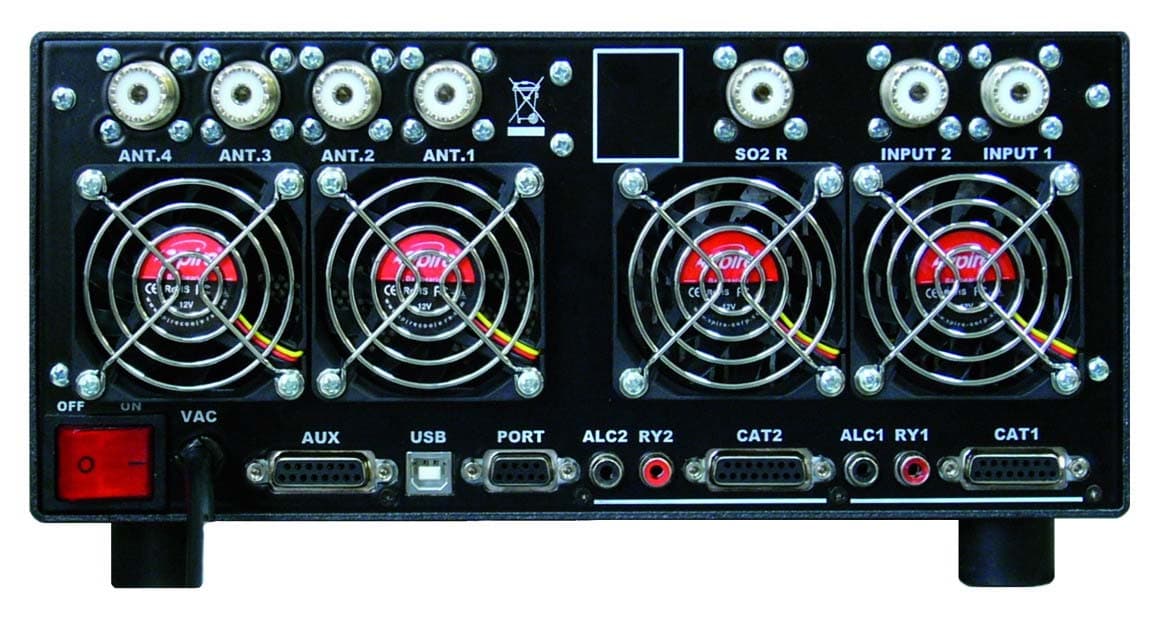
Click to zoom
Application Details
- Equipment Class
- AMP - Amplifier
- Date of Grant
- Jan 21, 2015
- Application Purpose
- Original Equipment
- Date of Application
- Nov 12, 2014
- Equipment Note
- Linear amplifier for radio amateur use
- Frequency Range
- 1.80000000 - 54.00000000
- Company
- S.P.E. s.r.l.
- Country
- Italy
Documents & Files
Document Text
Text extracted from the exhibit documents filed with the FCC. Open a document above to read the original.
Users Manual
Via di Monte Verde 33 – 00152 Rome – Italy. Tel. (39-6) 58209429 Fax (39-6) 58209647 Website www.linear-amplifier.com e_mail [email protected] Exhbit 6 - Pag. 1 of 1 Exhibit 6: User’s Manual External Radio Frequency Linear Amplifier Model Expert 1.3K-FA User manual EXPERT 1.3K-FA EXPERT 1.3K-FA 1.3KW SOLID STATE FULLY AUTOMATIC LINEAR AMPLIFIER USER’S MANUAL Rev. 1.0 Exhbit 6 – Pag. 2 of 2 User manual EXPERT 1.3K-FA Index IMPORTANT......................................................................................................................................................5 PRECAUTIONS..................................................................................................................................................5 UNPACKING......................................................................................................................................................8 1. PANEL DESCRIPTION...........................................................................................................................9 1.1 Front Panel.......................................................................................................................................9 1.2 Rear Panel......................................................................................................................................10 2. GENERAL INFORMATION...................................................................................................................11 2.1 Power supply..................................................................................................................................11 2.2 Input / Output..................................................................................................................................11 2.3 ALC / RELAY / CAT........................................................................................................................11 3. INTERCONNECTION WITH THE TRANSCEIVER..............................................................................13 4. USE OF THE LINEAR AMPLIFIER.......................................................................................................14 4.1 SO2R (Single Operator Two Radio ).............................................................................................15 4.2 BAND-PASS FILTERS SET “SPE BPF1”......................................................................................16 4.3 QSK (FULL BREAK-IN) OPERATION...........................................................................................17 4.4 TUNABLE ANTENNA CONTROL................................................................................................18 4.5 SETTING UP A SINGLE ANTENNA FOR RECEPTION...............................................................20 4.6 TWO POSSIBLE SETS OF ANTENNAS.......................................................................................20 4.7 WITH OR WITHOUT ATU..............................................................................................................20 5. EXTERNAL GROUND CONNECTION................................................................................................21 6. ANTENNA............................................................................................................................................22 7. POWER SUPPLY (PSU)...................................................................................................................23 8. TUNER (ATU) – WHERE FITTED....................................................................................................24 9. PROTECTIONS / ALARMS..................................................................................................................26 10. PROGRAMMING..................................................................................................................................27 10.1 Ways to operate.............................................................................................................................27 11. INITIAL OPERATION OF THE AMPLIFIER.........................................................................................30 11.1 Initial Programming.........................................................................................................................30 11.2 Operating.......................................................................................................................................31 12. CONNECTIONS...................................................................................................................................33 12.1 CAT Connector..............................................................................................................................33 12.2 ICOM.............................................................................................................................................34 CAT CI–V Interface........................................................................................................................34 12.3 KENWOOD...................................................................................................................................35 CAT RS232 Interface.....................................................................................................................35 CAT 5V TTL Interface.....................................................................................................................35 12.4 YAESU..........................................................................................................................................36 CAT RS232 Interface.....................................................................................................................36 CAT 5V TTL Interface.....................................................................................................................36 BAND DATA Interface..................................…
Text truncated - open the document above for the full version.
Attestation Statements
Via di Monte Verde 33 – 00152 Rome – Italy. Tel. il Exhibit 9: OpeAdditional Information in response to 47 CFR Ch.1 Sec. 2.1033 External Radio Frequency Linear Amplifier Model Expert 1.3K-FA (39-6) 58209429 Fax (39-6) 58209647 Website www.linear-amplifier.com [email protected] Pag. 1/ 4 Exhibit 9 Via di Monte Verde 33 – 00152 Rome – Italy. Tel. (39-6) 58209429 Fax (39-6) 58209647 Website www.linear-amplifier.com e_mail [email protected] Additional Information in response to 47 CFR Ch.1 Sec. 2.1033 Section c.1. The Expert 1.3K-FA Linear Amplifier will be assembled and production testing performed in Italy (Rome) by S:P:E: (SOCIETA’ PER L’ELETTRONICA) s.r.l. The Company is located in via di Monteverde 33 – 00152 Rome Italy. The President and principal owner of S:P:E: is Dr. Eng. Scasciafratti Gianfranco. The Company has designed and manufactured the EXPERT 1K-FA HF + 50 MHz linear amplifier accepted as FCC ID: UW31K-FA and the EXPERT 2K-FA HF + 50 MHz linear amplifier accepted as FCC ID: Y9C2K-FA both are in volume production and are being presently marketed in the Unites States. Applicant for certification is S:P:E: s.r.l. Rome Italy. Applicant is responsible for all aspects of quality assurance, marketing and service, as well as for the compliance with FCC rules. Applicant has conducted or observed all design-proof testing and will re-test samples of production equipment on an ongoing basis to ensure conformance to Applicant’s quality standards, including all FCC regulatory requirements. Section c.2. This product designed “SPE EXPERT 1.3K-FA” hereafter “EXPERT 1.3K-FA” is an external radio frequency power amplifier that covers all amateur bands from 1.8 MHz through 29.7 MHz and from 50 MHz to 54 MHz and provides up to1500 W PEP output power in all bands with a gain of not more than 15 dB. The EXPERT 1.3K-FA will be marketed in the United States for use for the Amateur Radio Service. The FCC identifier for the EXPERT 1.3K-FA will be 2ADK5GC324809. Section c.3. A copy of the Installation and Operating Instruction for the EXPERT 1.3K-FA is included as Exibit 6. Section c.4. The equipment is suitable for all types of emission authorized for amateur use in 97.305 of FCC rules. Section c.5. The equipment is designed to meet all specification and FCC performance standards on all amateur band from 1.8 MHz to 29.7 MHz and from 50 to 54 MHz. When derived to any buyer within FCC’s Pag. 2/ 4 Exhibit 9 Via di Monte Verde 33 – 00152 Rome – Italy. Tel. (39-6) 58209429 Fax (39-6) 58209647 Website www.linear-amplifier.com e_mail [email protected] jurisdiction, the equipment is not operable in CB band, the amplifier possesses none of the prohibited characteristics listed in section. FCC 97.317(b). Section c.6. The equipment can be operated at the maximum power “MAX” state automatically using the ALC link. To reduce the amplifier output, if required, it is necessary only to set the amplifier to “MID” or “LOW” power state rather than changing the transceiver drive power. It is also possible to regulate continuously the amplifier output power by changing the level of drive power from the transceiver. Section c.7. The equipment is rated for maximum RF power output of 1300 W PEP, with a continuous signal is limited to 1000 W. Section c.8. Normal currents and voltages are: “MAX” (1300 W), PA voltage 48 Vdc, 40 Adc. “MID” (950 W), PA voltage 36 Vdc, 34 Adc. “LOW” ( 500 W), PA voltage 32 Vdc, 22 Adc. Section c.9. The amplifier has an automatic tuner that handles load mismatches up to 3:1 VSWR (2.5:1 for 50 MHz). The amplifier contains a look-up table with the amateur bands only (continuous coverage is inhibited, including CB band). For the tuner management, antenna data and other working data are stored. Every band has a sub-band set, and for each of those, data related to the antenna and auto-ATU tuning is stored. The procedure description is included in Exhibit 11, as well as in the User’s Manual – Exhibit 6. Section c.10. Several features of the EXPERT 1.3K-FA design are specifically intended to reduce spurious radiation to a minimum. The input circuit having a 8 dB attenuator ensures that VSWR of 1.3:1 or less is presented to the exciter at the RF input terminal over the entire frequency range. The output circuit uses a well designed low pass filter unit which suppresses the harmonic emissions. Results of EXPERT 1.3K-FA RF performance and spurious emissions are included as Exhibit 5. Pag. 3/ 4 Exhibit 9 Via di Monte Verde 33 – 00152 Rome – Italy. Tel. (39-6) 58209429 Fax (39-6) 58209647 Website www.linear-amplifier.com e_mail [email protected] Pag. 4 / 4 Exhibit 9 Section c.11. A photograph showing the design of the FCC identification label for the EXPERT 1.3K-FA is included as Exhibit 1. Section c.12. Photographs showing the construction and layout of the EXPERT 1.3K-FA are included as Exhibit 2 and Exhibit 7. Section c.13. Not applicable to external RF power amplifier. Section c.14. Not applicable, as provided in Section c.15. Section c.15. Measurement data indicating compliance with requirements of Part 97.307 and Part 97.317 is included as Exhibit 5 and Exhibit 10. Section c.16. Not applicable to external RF power amplifier. Section c.17. Not applicable to external RF power amplifier. The subject application is not part of a composite system.
Attestation Statements
Via di Monte Verde 33 – 00152 Rome – Italy. Tel. (39-6) 58209429 Fax (39-6) 58209647 Website www.linear-amplifier.com e_mail [email protected] Pag. 1 / 1 Exhibit 10 Exhibit 10: Measurements Demonstrating Conformance to 97.307 and 97.317 External Radio Frequency Linear Amplifier Model 1.3K-FA Via di Monte Verde 33 – 00152 Rome – Italy. Tel. (39-6) 58209429 Fax (39-6) 58209647 Website www.linear-amplifier.com e_mail [email protected] Pag. 2 / 2 Exhibit 10 Measurements Demonstrating Conformance to 97.307 and 97.317 Amplifier under test operated at frequency f1 with CW (A1A) excitation. Spectrum Analyzer with a 60 dB input attenuator was used to observe all frequencies, from f1 through at least 10f1 for harmonic and spurious emissions. 97.317(a)(1)(2)(3) & 97.317(b). Spurious Emission per 97.307(c)(d)(e) and Gain versus frequency. Power Gain per 97.317 (a), (2). Spurious emission per 97.307 (d), (e). Frequency f1 MHz Input Power, W Output Power, W Amplifier Gain, dB 2f1 dBc 3f1 dBc 4f1 dBc 5f1 dBc 6-10 f1 dBc worst case 1.900 44.5 1300 14.6 -59.9 -54.6 > -70 -51.9 > -60 3.750 43.5 1300 14.7 -57.6 -54.7 > -70 -54.4 > -60 7.150 45.4 1300 14.2 -59.4 -60.7 > -70 -47.8 > -60 10.125 45.4 1300 14.2 > -70 -63.8 > -70 -47.3 > -60 14.175 44.0 1300 14.7 -53.7 -60.5 > -70 -60.0 > -60 18.100 43.7 1300 14.7 -64.0 > -70 > -70 -60.9 > -70 21.225 44.4 1300 14.6 -66.5 -55.7 > -70 > -70 > -70 24.930 44.5 1300 14.6 -48.5 > -70 > -70 > -70 > -70 28.500 43.7 1300 14.7 55.0 > -70 > -70 -61.6 > -65 50.250 46.0 1300 14.5 > -70 > -70 > -70 > -70 > -70 The amplifier conforms per 97.317 (a), (1). See Spurious emission per 97.307 (d), (e). The Power Gain was less than 15 dB. See Power Gain per 97.317 (a), (2). Amplifier was not capable of operation on any frequency outside the radio amateur band, 26-28 MHz included, for the look-up table in its software per 97.317 (a), (3). Conformance to 97.317 (b), (1), (2). To meet the requirements of 97. 317(a)(3), and (b) the equipment employs an internal software lock-up table, it ensures that the only frequencies permitted are in the radio amateur bands with the exclusion of the 26 – 28 MHz segment. Via di Monte Verde 33 – 00152 Rome – Italy. Tel. (39-6) 58209429 Fax (39-6) 58209647 Website www.linear-amplifier.com e_mail [email protected] Pag. 3 / 3 Exhibit 10 Spurious Emission per 97.307(a)(b). Intermodulation in dB per 97.307 (a),(b) Freq. (MHz) Output Power W Pep D3 dB D5 dB D7 dB D9 dB D11 and higher dB 1.800 1000 -30.8 -43.5 -43.5 >-51.3 > -60 3.750 1000 -34.9 -49.8 -48.0 -51.9 > -60 7.150 1000 -33.6 -44.2 -51.2 -55.4 > -60 10.125 1000 -32.3 -43.7 -51.2 -55.4 > -60 14.175 1000 -32.2 -47.2 -51.5 -52.7 > -60 18.100 1000 -31.3 -43.1 -59.4 -55.9 > -60 21.225 1000 -31.4 -43.8 -57.7 -55.8 > -60 24.930 1000 -30.2 -47.2 -53.7 -53.6 > -60 28.500 1000 -30.8 -49.8 -51.9 -52.6 > -60 50.250 1000 -31.1 -45.4 -54.7 > -55.3 > -60 Linear EXPERT 1.3K-FA conforms: 97.317(a)(1): Meets the spurious emission standards 97.307(d)(e) when the amplifier is operated at the its full output power and when the amplifier in the “standby” or “off” positions while connected to the transmitter. 97.317(a)(2): The Power Gain does not exceed 15 dB. 97.317(a)(3): Amplifier is not capable of operation on any frequency outside the radio amateur band, 26-28 MHz included, for the look-up table in its software. 97.317(b)(1)(2): The amplifier possesses none of the prohibited characteristics listed in this section. 97.317: The amplifier meets the spurious emission standards per 97.307(a)(b)(d)(e).
Block Diagram
Via di Monte Verde 33 – 00152 Rome – Italy. Tel. ( il i Exhibit 3: Block Diagram External Radio Frequency Linear Amplifier Model Expert 1.3K-FA 39-6) 58209429 Fax (39-6) 58209647 Website www.linear-amplifier.com [email protected] Pag. 1/ 2 Exhibit 3 Via di Monte Verde 33 – 00152 Rome – Italy. Tel. (39-6) 58209429 Fax (39-6) 58209647 Website www.linear-amplifier.com e_mail [email protected] Pag. 2/ 2 Exhibit 3 Block Diagram The position of the contacts, as shown in the diagram, is the situation of the linear amplifier in OFF state. The linear amplifier can be used in the following ways: 1) OFF: Only two direct connections are actuated: a) Between INPUT 1 and ANT 1. b) Between INPUT 2 and SO2R. 2) STANDBY: All the functions are activated (band change, antenna change, tuner control) but the transmission is from the transceiver only. 3) OPERATE: All the functions are activated and the transmission is using the linear amplifier.
External Photos
Via di Monte Verde 33 – 00152 Rome – Italy. Tel. ( il i Exhibit 2: External Photos External Radio Frequency Linear Amplifier Model Expert 1.3K-FA 39-6) 58209429 Fax (39-6) 58209647 Website www.linear-amplifier.com [email protected] Pag. 1/ 2 Exhibit 2 Via di Monte Verde 33 – 00152 Rome – Italy. Tel. (39-6) 58209429 Fax (39-6) 58209647 Website www.linear-amplifier.com e_mail [email protected] Pag. 2/ 2 Exhibit 2 External photos Pic. 1 Front View Pic. 2 Rear View
ID Label/Location Info
Via di Monte Verde 33 – 00152 Rome – Italy. Tel. ( il i Exhibit 1: ID Label Location Info External Radio Frequency Linear Amplifier Model 1.3K-FA 39-6) 58209429 Fax (39-6) 58209647 Website www.linear-amplifier.com [email protected] Pag. 1/ 3 Exhibit 1 Via di Monte Verde 33 – 00152 Rome – Italy. Tel. (39-6) 58209429 Fax (39-6) 58209647 Website www.linear-amplifier.com e_mail [email protected] FCC ID and Label Location Information In compliance with FCC Regulation 47 CFR Ch 1 part 2.925, the EXPERT 1.3K-FA, Linear Amplifier bears a label located on the rear plate of the equipment which displays the following FCC Identifier: Part (a) 1. The term FCC ID followed by the five digit Grantee Code and the Equipment Product Code; 2. Not applicable; 3. Not applicable. Part (b) Not applicable Part (c) Reserved Part (d) 1. The EXPERT 1.3K-FA label is indelibly printed on the middle of the rear panel of the equipment. This label will last the lifetime of the equipment in the environment in which the equipment will be operated and is not readily detachable. 2. The EXPERT 1.3K-FA label is readily visible on the outside of the equipment back panel. Part (e) Not applicable. Part (f) Not applicable. Part (g) The size of the label is 1.1 x 0.83 inc. The actual label and its location on the equipment are shown in the following pictures. Pag. 2/ 3 Exhibit 1 Via di Monte Verde 33 – 00152 Rome – Italy. Tel. (39-6) 58209429 Fax (39-6) 58209647 Website www.linear-amplifier.com e_mail [email protected] Pag. 3/ 3 Exhibit 1 PIC 1 Label Location PIC. 2 Actual Label In the Serial No.YYWWXXXX, the Ys represent the Year, the Ws represent the Weak and the Xs represent the serialized units in order of manifacture. In the FCC ID: 2ADK5GC324809, the Grantee code is 2ADK5 and the Equipment Product Code is GC324809.
Internal Photos
Via di Monte Verde 33 – 00152 Rome – Italy. Tel. ( il i Exhibit 7: Internal Photos External Radio Frequency Linear Amplifier Model Expert 1.3K-FA 39-6) 58209429 Fax (39-6) 58209647 Website www.linear-amplifier.com [email protected] Pag. 1/ 4 Exhibit 7 Via di Monte Verde 33 – 00152 Rome – Italy. Tel. (39-6) 58209429 Fax (39-6) 58209647 Website www.linear-amplifier.com e_mail [email protected] Internal Photos Pic. 1 - Top View Pic. 2 - Top View ( screen cover removed ) Pag. 2/ 4 Exhibit 7 Via di Monte Verde 33 – 00152 Rome – Italy. Tel. (39-6) 58209429 Fax (39-6) 58209647 Website www.linear-amplifier.com e_mail [email protected] Pic. 3 - Bottom View Pic. 4 - Right Side View Pag. 3/ 4 Exhibit 7 Via di Monte Verde 33 – 00152 Rome – Italy. Tel. (39-6) 58209429 Fax (39-6) 58209647 Website www.linear-amplifier.com e_mail [email protected] Pag. 4/ 4 Exhibit 7 Pic. 5 - Left Side View Pic. 6 – Switching Power Supply View (screen cover removed)
Internal Photos
Via di Monte Verde 33 – 00152 Rome – Italy. Tel. (39-6) 58209429 Fax (39-6) 58209647 Website www.linear-amplifier.com e_mail [email protected] Pag. 1 / 6 Bottom Wiew Photos of all Circuit Boards External Radio Frequency Linear Amplifier Model Expert 1.3K-FA Via di Monte Verde 33 – 00152 Rome – Italy. Tel. (39-6) 58209429 Fax (39-6) 58209647 Website www.linear-amplifier.com e_mail [email protected] Pag. 2 / 6 Pic. 1 - Amplifier Pic. 2 - SWR Tuner Meter Via di Monte Verde 33 – 00152 Rome – Italy. Tel. (39-6) 58209429 Fax (39-6) 58209647 Website www.linear-amplifier.com e_mail [email protected] Pag. 3 / 6 Pic. 3 - HAM Filters Pic. 4 - Tuner (ATU) Via di Monte Verde 33 – 00152 Rome – Italy. Tel. (39-6) 58209429 Fax (39-6) 58209647 Website www.linear-amplifier.com e_mail [email protected] Pag. 4 / 6 Pic. 5 - SWR Antenna Meter Pic. 6 - Antenna Selector Via di Monte Verde 33 – 00152 Rome – Italy. Tel. (39-6) 58209429 Fax (39-6) 58209647 Website www.linear-amplifier.com e_mail [email protected] Pag. 5 / 6 Pic. 7 – CPU without the cables connected Pic. 8 – CPU bottom side Via di Monte Verde 33 – 00152 Rome – Italy. Tel. (39-6) 58209429 Fax (39-6) 58209647 Website www.linear-amplifier.com e_mail [email protected] Pag. 6 / 6 Pic. 9 – Front Panel Boards DX Pic. 10 – Front Panel Boards SX
Operational Description
Via di Monte Verde 33 – 00152 Rome – Italy. Tel. ( il i Exhibit 8: Operational Description External Radio Frequency Linear Amplifier Model Expert 1.3K-FA 39-6) 58209429 Fax (39-6) 58209647 Website www.linear-amplifier.com [email protected] Pag. 1/ 3 Exhibit 8 Via di Monte Verde 33 – 00152 Rome – Italy. Tel. (39-6) 58209429 Fax (39-6) 58209647 Website www.linear-amplifier.com e_mail [email protected] Operational Description The SPE Expert 1.3K-FA solid state linear amplifier is small, powerful and completely automatic, covers all the amateurs bands from 1.8 to 54 MHz. Being only 7.5 Kg. (16.5 Ibs), it is perfect for use in the shack and is superior to for DXpeditions. All operating conditions (frequency, antenna, tuner etc.) are controlled from the transceiver. The operator has to only move the frequency-tuning knob, it is extremely user-friendly and offers a product which is the best in its class. The linear amplifier has two inputs (INPUT 1, INPUT 2) to which it is possible to connect two transceivers of any brand or type. These inputs are selected with the [INPUT] key or automatically. It can manage up to four antennas (ANT 1, ANT 2, ANT 3, ANT 4). The amplifier selects antennas automatically when they have been programmed. The amplifier is constituted by a class AB single push-pull performed by a just one dual mosfet device. This simplifies the design and increases the reliability of the amplifier. The modern transceivers have CAT control, thanks to this link the linear amplifier detects the operating frequency of the transceiver and then automatically changes band, antenna and automatic tuner. The power supply of the SPE Expert 1.3K-FA, unique in its category, is switching with a PFC (Power Factor Correction) that allows a drastic reduction of the harmonic components in the mains in accordance with IEC555-2. The power supply meets also the followings rules: UL60950-1, TUV EN60950-1, EN55022, EN61000-3-2,- 3, EN61000-4-2,3,4,5,6,8,11; ENV50204, EN5502. It consists of two separate elements: The first powers all the electronic circuits for command and control. The second powers only the PA, its output voltages are 48 Vdc (MAX Pout), 36 Vdc (MID Pout), and 32 Vdc (LOW Pout). The amplifier has an automatic tuner that handles load mismatches up to 3:1 VSWR (2,5:1 for 50 MHz). A unique feature of this linear is that it not only measures the SWR after the matching, but also the SWR of the system antenna / cable, this allows to always evaluate the antenna system despite the matching and the power applied. The amplifier contains a look-up table with the permitted amateur bands only (continuous coverage is inhibited, including CB band). In the tuner management, antenna data and other working data are stored. Every band has a sub-band set, and for each of those, data related to the antenna and auto-ATU tuning is stored. Pag. 2/ 3 Exhibit 8 Via di Monte Verde 33 – 00152 Rome – Italy. Tel. (39-6) 58209429 Fax (39-6) 58209647 Website www.linear-amplifier.com e_mail [email protected] Pag. 3 / 3 Exhibit 8 The CAT information and the frequency counter inside the linear detect the operating frequency and set the correct sub-band. Thanks to the stored data, the tuner and the antenna are automatically set correctly. Setting of the match data to write in the tables is performed automatically by pressing the [TUNE] key, the system will then find the correct match for minimum SWR. The internal tuner may be bypassed as follows: - Totally. - For single band. - For single band and specific antenna. It is always automatically bypassed: - With the only receiving antenna set. - With tunable antenna set. The SPE Expert 1.3K-FA has a sophisticated protection system that constantly controls the amplifier’s most important parameters. These main parameters are: Temperature of the heatsink; max. / min. voltage on the PA; max. PA current; SWR; max voltage RF on the tuner; input power. The protection system is effected in two different ways: 1) Through hardware circuits to guarantee minimum intervention time. 2) Through software, with one of the two CPU’s, to guarantee the maximum precision. The two results are always compared, every difference produces a protection trip and consequent alarm.
Parts List/Tune Up Info
Via di Monte Verde 33 – 00152 Rome – Italy. Tel. ( il i Exhibit 11: Tuning Procedure External Radio Frequency Linear Amplifier Model 1.3K-FA 39-6) 58209429 Fax (39-6) 58209647 Website www.linear-amplifier.com [email protected] Pag. 1/ 3 Exhibit 11 Via di Monte Verde 33 – 00152 Rome – Italy. Tel. (39-6) 58209429 Fax (39-6) 58209647 Website www.linear-amplifier.com e_mail [email protected] Tuning Procedure TUNER (ATU) The amplifier has an automatic tuner that handles load mismatches up to 3:1 VSWR (2.5:1 for 6 m).The amplifier contains a look-up table with all the permitted bands. For tuner management, antenna data and other working data are stored. Every band has a sub-band set, and for each of those, data related to the antenna and auto-ATU tuning is stored. The CAT and the frequency counter detect the operating frequency and the correct sub-band. Thanks to the stored data, the tuner and the antenna are automatically set correctly. The amplifier is equipped with two different memory banks, "Bank A" and "Bank B", which one can use to store two different configurations. This feature is particularly useful if one participates in a DXpedition. If one of the memory banks is set as home station, when back, just recall the proper memory bank. Furthermore, table driven management is useful to inhibit operation of the amplifier, for instance when an antenna for a particular band is not available. All auto-tuner functions remain, on standby, whilst using the transceiver only. Setting of the match data to write to the tables is performed automatically by pressing the [TUNE] key The system will then find the correct match for minimum SWR. To achieve a better match than that achieved with the automatic tune routine (most unlikely) it is possible to set the tuning manually by using the keys [◄C], [C►], [◄L], [L►]. When manual tuning has been performed, it is possible to read the tuning value, the working frequency and the associated sub-band on the appropriate screen page. Both the types of tuning are always effected in “STANDBY“ state. Before beginning the matching process, the tuner measures the SWR of the system cable / antenna. if it is greater than 3.5:1, the procedure does not begin and an alarm is given. It is possible to bypass the tuner with a specific command, in order to use an external tuner. NEVER USE THE INTERNAL TUNER WITH AN EXTERNAL ONE, it could seriously damage the linear. IF YOU WANT USE AN EXTERNAL TUNER, BEFORE EXCLUDE THE INTERNAL ONE. The internal tuner may be excluded: - Totally. - For single band. - For single band only with a specific antenna. It is always automatically excluded: - With the only receiving antenna set - With tunable antenna set. Note: the tuner, like all analog circuits, introduces a loss (0,8 dB max.) that may vary with tuning conditions. The power meter of the amplifier does not show this loss as the power is measured at the tuner input where the load resistance is always constant (50 ohm). Pag. 2/ 3 Exhibit 11 Via di Monte Verde 33 – 00152 Rome – Italy. Tel. (39-6) 58209429 Fax (39-6) 58209647 Website www.linear-amplifier.com e_mail [email protected] Pag. 3 / 3 Exhibit 11 Note: ATTENTION: When the amplifier is either in “STANDBY” or “OPERATE” mode, always disable the automatic tuner in your transceiver. SET ANTENNA. Press [SET] and open the “ANTENNA“ menu page. Assign an appropriate antenna for the band concerned. If you don’t have an antenna for a band, input “N“. When all the antennas are programmed, exit and go back to STANDBY. USE OF AUTOMATIC TUNER. To complete the programming it is necessary to match the antennas to the amplifier by operating “TUNE“ function. (read the “TUNER“ chapter of the manual). We recommend that you select each band (with available antenna) and then program the tuner for the sub- bands within which you will operate. Refer to the table in section 19 of the manual to select the appropriate sub-bands for your operating preferences. You are strongly advised to proceed with the utmost accuracy, not just match the current frequency, but all matching all the antennas on all bands that are available, allows you to enjoy all the features of the automatic linear. To program the sub-bands, proceed as follows: 1) For every band find the central frequency in the table of each sub-band (refer to section 19 of the manual). Then set the transceiver to that frequency. 2) Next, set your transceiver to transmit a continuous tone (RTTY or FM). 3) Then press the [TUNE] key and then the PTT. The procedure for automatic tuning will start. You will hear the ATU relays operate and when they stop, the SWR will be at a minimum. Sometimes it is possible to improve tuning by repeating this step. 4) Repeat the previous steps for all sub-bands of bands you wish to use. 5) Repeat the previous steps for other antennas of the same band after having selected it using the [ANT] key. Note: if the ALC link is not used, it is preferable to reduce the transceiver power to about 30 Watts during this operation.
Test Report
Via di Monte Verde 33 – 00152 Rome – Italy. Tel. ( il i Exhibit 5: EMI Test Report External Radio Frequency Linear Amplifier Model Expert 1.3K-FA 39-6) 58209429 Fax (39-6…
Text truncated - open the document above for the full version.
Contact Information
Applicant
Gianfranco Scasciafratti(Dr.)
Technical Specifications
| # | Rule Parts | Frequency Range | Power Output | Emission | Tolerance |
|---|---|---|---|---|---|
| 1 | 97 | 1.8 MHz - 54 MHz | 1300 W | H3A | Amp |