2ADK9TP200Tyre Pressure Monitoring System
Shenzhen Carmate Electronic Technology Co., Ltd.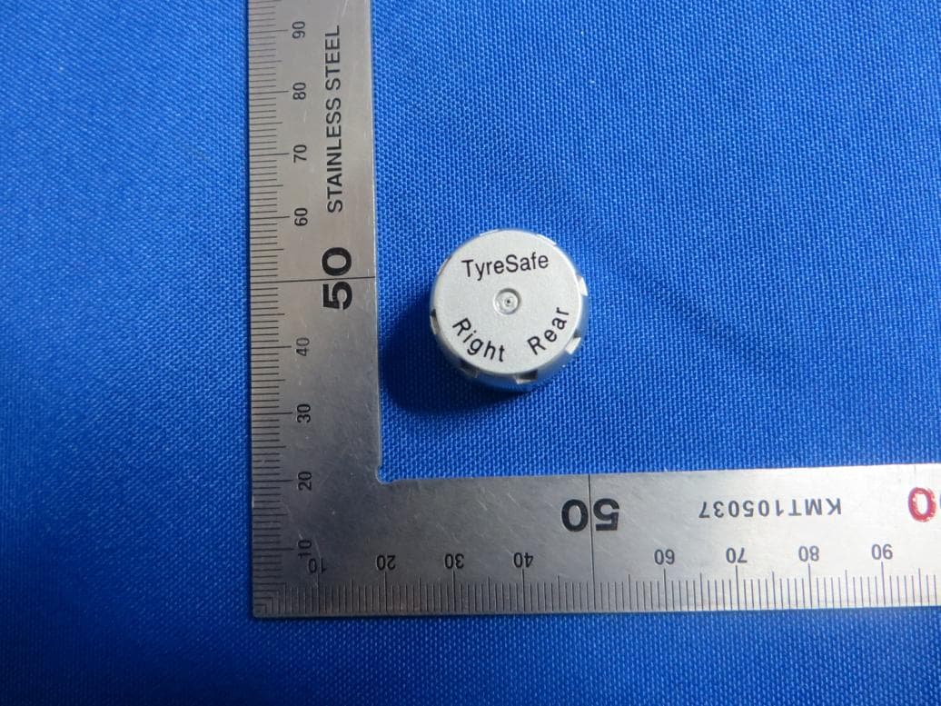
Click to zoom
Application Details
- Equipment Class
- DSC - Part 15 Security/Remote Control Transmitter
- Date of Grant
- Nov 17, 2014
- Application Purpose
- Original Equipment
- Date of Application
- Nov 17, 2014
- Equipment Note
- Tyre Pressure Monitoring System
- Frequency Range
- 433.92000000 - 433.92000000
- Country
- China
Documents & Files
Document Text
Text extracted from the exhibit documents filed with the FCC. Open a document above to read the original.
Users Manual
TPMS TP200 User Manual Tire Pressure Monitor System CONTENTS Packing List ............................................................................ 1 Display Power On ................................................................... 2 Sensor Installation .................................................................. 3 Driving Checking .................................................................... 4 USB Charging Socket ............................................................. 4 Display Functions ................................................................... 5 Sensor Exploded View ............................................................ 8 Replace Sensor Battery .......................................................... 9 Technical Parameter ............................................................... 15 Pressure Unit Switching .......................................................... 13 Leakage Reasons of Nonstandard Tire Valve ......................... 14 Notes and Statement ............................................................... 16 2 Ways to Exit Code Learning Mode ........................................... 12 FAQ ....................................................................................... 15 Code Learning ....................................................................... 10 1 ① ② Packing List Pressure Unit Warning Value of Tire Pressure Temperature Unit Tire Pressure Query Button USB Charging Socket Uncap Wrench (for replacing battery) Display Sensor 4ps Hexagonal Nut 5pcs (one for backup) Nut Wrench (valve core wrench) Silicon Seal Ring 4pcs(for backup) If the silicon seal ring is damaged, please replace it by the backup ring for avoiding leakage. As shown in page 8 picture 3 - Replace Sensor Battery. ① ② for pulling out the silicon seal ring for setting the silicon seal ring ( for replacing the silicon seal ring) Ring Needle 2 1 2 ON 3 4 Display Power On Pull out the cigar lighter Plug in the display ACC ON Display power on, and start to receive data. 3 Sensor Installation 1 Backout dustproof cap of tire valve. 2 Screw- in the hexagonal nut. Screw- in the sensor in proper tire according to the mark in the shell. 3 Tighten the sensor by nut wrench in reverse direction. 4 5 Check if it is leaking with soapsuds. 4 >20km/h 1 2 Driving Checking When the driving speed is up to 20km/h, the display will update the data of tire pressure automatically. There is a USB socket in display, it can charge some portable products such as mobile phone or MP3 while the tire pressure monitor is working. Output voltage: 5V Output current: 1A USB Charging Socket With display power on If all the 4 tire pressure date is shown 5 Bi-Bi-Bi-Bi-Bi- Display Functions all 4 tire pressure data shown The display will show all the tire pressure values right after the vehicle engine start. Leakage Warning It means the tire may be stick by nail or aged. Abnormal Pressure Warning The pressure is out of normal range 26 to 46Psi. Above 46 :Bi-Bi-Bi-Bi-Psi Below 26 Psi: BiBiBi--- Sensor Battery Run Out of Power The lifetime of sensor battery is over 3 years. 6 Bi- Bi-Bi- High Temperature Warning The tire temperature is higher than 65°C. Sensor Disabled Display Functions Temperature Query Press the query button once, siren beep once, the display will show as the follow picture, and then go back to tire pressure values after 4 seconds automatically. The display will show temperature unit if the tire temperature is above 0°C, and will show if it is under 0°C. 7 Display Functions Temperature Range The detected temperature range is from -40 to 99°C. The display will update the temperature values only when driving speed is up to 20km/h. Display will show temperature values as below when power on. 8 Sensor Exploded View Shell Sensor Silicon Seal Ring Anti-dismantle Locking Plate Hexagonal Nut Button Battery CR1632 9 Replace Sensor Battery Lithium Cell CR 1632 3V 1 Loosen the hexagonal nut. 2 Backout the sensor. Silicon seal ring (Red) Anti-dismantle locking plate 3 Take out the anti-dismantle locking plate. 4 Backout the shell with uncap wrench 5 Replace the new button battery 6 Assemble the sensor in reverse operation. 10 1 2 3 l o n g p r e s s Code Learning Before the sensor installed in tire, turn car key from ACC OFF to ACC ON, plug the display in the cigar lighter till it is working. Press the query button until the display beep once and twice next and then release (beep once and release means pressure unit switching). The display will show the order 01-02-03-04 for LF-RF-RR-LR sensors, and 01 starts to flash indicates LF sensor can be learned right now. 11 4 5 short press Code Learning Install the LF sensor in left-front tire, display will beep once and show the tire pressure value after 10 seconds, which means LF sensor already learned successfully. Press the query button once to enter the next sensor code learning. Display 02 starts to flash, install the RF sensor in right-front tire. And repeat above steps for rest sensors. If there is only one sensor need to be learned, press the query button one by one time until it shows the right tire. 1 Bi-Bi-Bi-Bi-Bi-Bi-Bi- 2 Bi-Bi- Bi-Bi-Bi-Bi-Bi-Bi-Bi- 12 2 Ways to Exit Code Learning Mode 1. After 4 sensors are learned successfully, the system will exit code learning mode after 20 seconds automatically, and the display will beep 7 times. 2.After4sensorsarelearnedsuccessfully,pressthequerybuttonuntil itbeep once and twice next and then releasetoexitcodelearning mode,andthedisplaywillbeep7timesnext. 20 seconds long press 13 Bi- ACC ON, after display is power on, whenever press the query button until it beeps once and release, the pressure unit can be switched between “Bar” and “Psi”. The factory default pressure unit is Psi. PressureUnitSwitching s h o r t p r e s s 14 Leakage Reasons of Nonstandard Tire Valve Standard Valve The valve core is even with the edge. The valve thread length ≥ 9mm Leakage Reason 1 of Nonstandard Tir…
Text truncated - open the document above for the full version.
Cover Letter(s)
Shenzhen Carmate Electronic Technology Co., Ltd. 3/F, Bldg 2, Hong Fa Industrial Park, Tang Tou Road, Shi Yan Town, Bao An District, Shenzhen, Guangdong, China 518108 ----------------------------------------------------------------------------------------------------------------------------------- Declaration of Authorization We Name: Shenzhen Carmate Electronic Technology Co., Ltd. Address: 3/F, Bldg 2, Hong Fa Industrial Park, Tang Tou Road, Shi Yan Town, Bao An District, Shenzhen, Guangdong, China 518108 Declare that: Name Representative of agent: Wu Jian Agent Company name: MRT Technology (Suzhou) Co., Ltd Address: D8 Building, Youxin Industrial Park, No.2 Tian'edang Rd., Wuzhong Economic Development Zone, City: Suzhou Country China is authorized to apply for Certification of the following product(s): Product description: Tire Pressure Monitor System FCC ID: 2ADK9TP200 Model: TP200, TP100, TP300 Brand: TyreSafe on our behalf. Signature: Ming Wu, Manager Date: 2014-11-13
External Photos
External Photo (1) EUT Photo (2) EUT Photo (3) EUT Photo (4) EUT Photo
ID Label/Location Info
FCC Label FCC Label Location FCC ID: 2ADK9TP200
Internal Photos
Internal Photo (1) EUT Photo (2) EUT Photo (3) EUT Photo (4) EUT Photo (5) EUT Photo (6) EUT Photo (7) EUT Photo
Test Report
MRT Technology (Suzhou) Co., Ltd Report No.: 1411RSU00101 Phone: +86-512-66308358 Report Version: V02 Fax: +86-512-66308368 Issue Date: 11-18-2014 Web: www.mrt-cert.com FCC ID: 2ADK9TP200 Page Number: 1 of 26 FCC ID: 2ADK9TP200 APPLICANT: Shenzhen Carmate Electronic Technology Co., Ltd. Application Type: Certification Product: Tyre Pressure Monitoring System Model No.: TP200, TP100, TP300 FCC Classification: FCC Part 15 Security/Remote Control Transmitter(DSC) FCC Rule Part(s): Part 15.231(e) Test Procedure(s): ANSI C63.10-2009 Test Date: N o v. 10 ~ 17, 2014 MEASUREMENT REPORT FCC PART 15.231(e) Reviewed By : ( Robin Wu ) Approved By : ( Marlin Chen ) The test results relate only to the samples tested. This equipment has been shown to be capable of compliance with the applicable technical standards as indicated in the measurement report and was tested in accordance with the measurement procedures specified in ANSI C63.10-2009. Test results reported herein relate only to the item(s) tested. The test report shall not be reproduced except in full without the written approval of MRT Technology (Suzhou) Co., Ltd. Report No.: 1411RSU00101 FCC ID: 2ADK9TP200 Page Number: 2 of 26 Revision History Report No. Version Description Issue Date 1411RSU00101 Rev. 01 Initial report 11-17-2014 1411RSU00101 Rev. 02 Update the emission data and the transmission time plot 11-18-2014 Report No.: 1411RSU00101 FCC ID: 2ADK9TP200 Page Number: 3 of 26 CONTENTS Description Page 1. INTRODUCTION ..................................................................................................................... 6 1.1. Scope ........................................................................................................................... 6 1.2. MRT Test Location ....................................................................................................... 6 2. PRODUCT INFORMATION ..................................................................................................... 7 2.1. Equipment Description .................................................................................................. 7 2.2. Test Standards ............................................................................................................. 8 2.3. Test Methodology ......................................................................................................... 8 2.4. EUT Setup and Test Mode ........................................................................................... 8 3. ANTENNA REQUIREMENTS .................................................................................................. 9 4. TEST EQUIPMENT CALIBRATION DATA ............................................................................ 10 5. MEASUREMENT UNCERTAINTY .......................................................................................... 11 6. TEST RESULT ...................................................................................................................... 12 6.1. Summary .................................................................................................................... 12 6.2. Radiated Emissions .................................................................................................... 13 6.2.1. Standard Applicable ................................................................................................ 13 6.2.2. Test Procedure ........................................................................................................ 13 6.2.3. Te s t Setup ............................................................................................................... 14 6.2.4. Test Results ............................................................................................................ 15 6.3. 20dB Bandwidth ......................................................................................................... 19 6.3.1. Standard Applicable ................................................................................................ 19 6.3.2. Te s t Procedure ........................................................................................................ 19 6.3.3. Te s t Setup ............................................................................................................... 19 6.3.4. Te s t Result .............................................................................................................. 20 6.4. Transmission Time ...................................................................................................... 21 6.4.1. Standard Applicable ................................................................................................ 21 6.4.2. Te s t Procedure ........................................................................................................ 21 6.4.3. Test Setup ............................................................................................................... 21 6.4.4. Test Result .............................................................................................................. 22 6.5. Duty Cycle .................................................................................................................. 24 6.5.1. Standard Applicable ................................................................................................ 24 6.5.2. Test Procedure ........................................................................................................ 24 6.5.3. Test Setup ............................................................................................................... 24 6.5.4. Test Result .............................................................................................................. 25 Report No.: 1411RSU00101 FCC ID: 2ADK9TP200 Page Number: 4 of 26 7. CONCLUSION ....................................................................................................................... 26 Report No.: 1411RSU00101 FC…
Text truncated - open the document above for the full version.
Test Setup Photos
1 of 2 Test Setup Photo Description: Radiated Emission Test Setup for 9kHz ~ 30MHz Description: Radiated Emission Test Setup for 30MHz ~ 1GHz Description: Radiated Emission Test Setup for 1GHz ~ 18GHz
Contact Information
Applicant
Ming Wu
Test Firm
MRT Technology (Suzhou) Co., LtdWu Jian
[email protected]86-512-66308358
Technical Specifications
| # | Rule Parts | Frequency Range | Power Output |
|---|---|---|---|
| 1 | 15.231 | 433.92 MHz - 433.92 MHz | - |