2ADKH-TXM1U10Transmitter Module
ARCT Inc.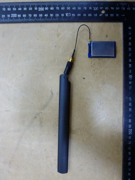
Click to zoom
Application Details
- Equipment Class
- TNB - Licensed Non-Broadcast Station Transmitter
- Date of Grant
- Jan 17, 2015
- Application Purpose
- Original Equipment
- Date of Application
- Jan 17, 2015
- Equipment Note
- Transmitter Module
- Frequency Range
- 450.01250000 - 469.98750000
- Company
- ARCT Inc.
- Country
- Taiwan
Documents & Files
Document Text
Text extracted from the exhibit documents filed with the FCC. Open a document above to read the original.
Users Manual
1 Operating Instructions Transmitter module Model No. TX0400P10 2 Read me first: Thank you for purchasing the ARCT TX0400P10 TX module. These operating instructions describe the instructions for the TX0400P10 TX module. Before connecting, operating this product, please read these instructions completely, and save this manual for future use. Model: TX0400P10 FCC ID: 2ADKH‐TXM1U10 Here by, we declare that this TX0400P10 Module is in compliance with Part 90 of the FCC Rules and essential requirements and other relevant provisions of directive 1999/5/EC. Operation is subject to the following two conditions: (1) This device may not cause harmful interference, and (2) This device must accept any interference received, including interference that may cause undesired operation. Warranty Policy: The warranty period and what is covered are according to applications, contracts or distributors. Please ask our sales representative. Note: The following damages are not covered by the warranty. ‐Any secondary damages, including without limitation, business chances. ‐Any damages by user including dropping, water contact or any other wrong use, other than the purpose designed for. 3 General Description TX0400P10 is based on RF Transceiver CC1175 of TI Chipcon, it’s a small size and ultra low power UHF wireless module. The CC1175 device is a fully integrated single-chip radio transmitter designed for high performance at very low-power and low-voltage operation in cost-effective wireless systems. All filters are integrated, thus removing the need for costly external SAW and IF filters. The device is mainly intended for the ISM (Industrial, Scientific, and Medical) and SRD (Short Range Device) frequency bands at 420–470 MHz. The MAX RF output power can be set as high as +14dBm, with data rate as high as 200Kbps. The module integrated many RF functions and PA to make the maximum output power up to +30dBm. Customer can use it conveniently and reducing your development time. Features Central frequency is 450MHz, Frequency bands :420~470MHz Programmable output power up to +30dBm for all supported frequencies,the communication distance is above 1200m in sight . Programmable baseband modulator with GFSK/2-FSK/ASK/OOK/MSK Programmable data rate 0.6~200Kbps 128-byte TX data FIFO Optional Forward Error Correction with Interleaving Transmit mode at +30dBm output power <950mA Low current consumption at power down state <2uA Integrated analog temperature sensor Efficient SPI interface, All registers can be programmed with one “burst” transfer Small dimension: 50.0mm×30.0mm×2.4 mm Operating supply voltage: 3.0~3.6V DC, PA supply voltage: 3.0~3.6V DC Applications One-way Narrowband Ultra-Low Power Wireless Systems With Channel Spacing Down to 6.25 kHz Wireless Metering and Wireless Smart Grid (AMR and AMI) IEEE 802.15.4g Systems Home and Building Automation Wireless Alarm and Security Systems Industrial Monitoring and Control Wireless Healthcare Applications Wireless Sensor Networks and Active RFID. Logistics Tracking System, Warehouse patrol, Electronic label. 4 General Characteristics Test operating conditions:Ta = 2 5° C,VCC=3.3V if nothing else stated. Parameter Type Condition/Note Operating supply voltage DC 3.0~3.6V Central frequency 450MHz Can be programmable to other frequency in bands 450~470MHz Frequency accuracy ±1KHz Modulation GFSK/2-FSK/ASK/OOK/MSK Programmable Transmit power -30~+10dBm CC1175 output power programmable TX current consumption <1000mA Po= 30dBm Sleep State current consumption <2uA Refer to IC operation states Data rate 0.6~200Kbps Programmable Spurious emissions and harmonics < -30dBm TX power +30dBm Communication distance >1200m 1.2kBaud data rata, CC1175 = +10dBm output power Antenna impedance 50ohm Operating temperature -20~+60 °C Storage temperature range 50~+125°C Dimension Note: 1. The module transmission data rate will affect Transmission distance , the higher the data rate , the closer the distance, and the lower the receiving sensitivity. 2. The supply voltage to the module will affect TX power, in the operating supply voltage range, the lower the voltage to get the lower the TX power. 3. The antenna will strongly affect the communication distance, please select matched antenna and connect it correctly. 4. The module mount will affect the communication distance. 5 PCB Description Pin Configuration Pin Pin type Description AVCC Power(Analog) 3~3.6V analog power supply connection AVCC Power(Analog) 3~3.6V analog power supply connection AVCC Power(Analog) 3~3.6V analog power supply connection GND Ground Connect to the system ground VPC1 Digital Input VPC2 Digital Input RF power control I/O VPC1 & VPC2 = 0, RF=+30dBm ; VPC1 =1 & VPC2 =0 RF = -20dBm ANT RF Oupt RF output signal from PA, connect to the Antenna NRESET Digital Input Asynchronous, active-low digital reset GPIO2 Digital I/O General-purpose I/O SI Digital Input Serial data in SCLK Digital Input Serial data clock SO Digital Input Serial data out GPIO0 Digital I/O General-purpose I/O CSN Digital Input Active-low chip select GND Ground Connect to the system ground 6 Circuit Interface Note: 1. The module power supply voltage range is DC 3.0~3.6V, above DC 3.6V, the module will damage. It is recommended work at DC 3.3 V, the PA supply voltage consider the application condition. 2. The module interface use half circle pad to soldering on the system PCB board, the GND must soldering to the system digital GND reliably, or use connector to connect main-board . 3. The antenna must the get to the module’s ANT pin as close as possible. 4. The MCU which don’t have integrated SPI interface can also control the module, use the normal I/O port to work like SPI timing to read and write. The SPI data rate is below 10MHz. 5. The interface can connect directly to the MCU which use 3.3V power supply, there is no need serial resistor. If the I/O is open-drain, the pull-up resistor will be added. When connect …
Text truncated - open the document above for the full version.
Cover Letter(s)
ARCT Inc. 8F., No.788, Zhongzheng Rd., Zhonghe Dist., New Taipei City 235, Taiwan (R.O.C.) Federal Communications Commission Equipment Authorization Branch 7435 Oakland Mills Road Columbia, MD 21046 Date: 2014112118 Request for Confidential ity Company name: ARCT lnc. FCC lD: 2ADKH-TXM1U10 FCC Part 90 Certification To whom it may concern: In accordance with 0.459 of CFR 47, ARCT Inc. hereby requests confidentiality of all Block Diagrams, Schematics, Operational Description attachments for the subject application. These documents contain detailed system and equipment description and related information about the product which ARCT Inc. considers to be proprietary, confidential and a custom design and otherwise would not release to the general public. Since the design is a basis from which future technological products will evolve, ARCT Inc. considers that this information would be of benefit to its competitors and that the disclosure of the information in these documents would give competitors an unfair advantage in the market. Signature Name: Tommy Lin Title: Manager Company: ARCT Inc.
Cover Letter(s)
ARCT Inc. 8F., No.788, Zhongzheng Rd., Zhonghe Dist., New Taipei City 235, Taiwan (R.O.C.) Date: 2014/12/29 Federal Communications Commission Authorization and Evaluation Division Equipment Authorization Branch 7435 Oakland Mills Road Columbia, MD 21046 Subject: Request for Module Approval. To whom may it concern: We have the following attestation to the eight requirements described by FCC public notice DA00-1407 "Part 90 Unlicensed Modular Transmitter Approval". 1. RF shielding. The model TX0400P10, (FCC ID:2ADKH-TXM1U10) has its own RF shielding. The shielding is made by metal and completely added to RF part during our manufacturing. It is not easily removed module. Please see exhibition external photos of this module. 2. Excessive data rates or over modulation. The module circuit buffers all modulation and control of the transmitter. The control of the transmitter is via data commands and software instructions contained within the module. The transmitter is tested with the module operated at the maximum power. Data commands are reduced the power of transmitter but do not influence the modulation contents. 3. Power supply regulation. The module has its own power supply regulator to insure compliance with part 90 requirements regardless of the quality or level of external Adapter supplying the module from the end product. The regulator operates within the DC 3.3V FCC ID: 2ADKH-TXM1U10 Contact person: Tommy Lin E-mail: [email protected] ARCT Inc. 8F., No.788, Zhongzheng Rd., Zhonghe Dist., New Taipei City 235, Taiwan (R.O.C.) 4. Antenna and unique coupler requirements to antenna connector. The antenna is Dipole antenna, please refer to antenna spec. (1) No modification of antenna will be allowed. (2) The end product must be certified by FCC, if customer will use the other antenna. 5. Stand--alone configuration. The modular transmitter has been performed the testing as a stand alone and then confirmed the compliance. Please refer to the test report number W6M21411-14611-C-1. 6. Label with own FCC ID number and exterior label. The module is labeled with own FCC ID number. Please see exhibition label sample for the FCC ID of this module. The label made by polyester sheet is affixed to the module by a high-strength adhesive. Since the FCC ID number will not be visible when the module is installed inside the end product, there are instructions give to the OEM how to label the end product. Please refer to the “User Manual”. 7. Compliant with any specific rule or operating requirements. The module as manufactured is completely controlled by the onboard processor. There are no influences to the operation of the transmitter the end can induce that will operate the module outside of scope of the regulations. The necessary explanation for user to be complied with this requirement is contained on the manual. 8. RF exposure requirements. To comply with FCC RF exposure compliance requirements, the antenna used for this transmitter must be installed to provide a separation distance of at least 0.65 m from all persons and must not be co-located or operating in conjunction with any other antenna or transmitter. Sincerely yours, Signature:
External Photos
Registration number: W6M21411-14611-C-1 FCC ID: 2ADKH-TXM1U10 Worldwide Testing Services(Taiwan) Co., Ltd. Appendix page 2 of 8 EUT Photos Registration number: W6M21411-14611-C-1 FCC ID: 2ADKH-TXM1U10 Worldwide Testing Services(Taiwan) Co., Ltd. Appendix page 5 of 8 Registration number: W6M21411-14611-C-1 FCC ID: 2ADKH-TXM1U10 Worldwide Testing Services(Taiwan) Co., Ltd. Appendix page 6 of 8 Registration number: W6M21411-14611-C-1 FCC ID: 2ADKH-TXM1U10 Worldwide Testing Services(Taiwan) Co., Ltd. Appendix page 7 of 8
Internal Photos
Registration number: W6M21411-14611-C-1 FCC ID: 2ADKH-TXM1U10 Worldwide Testing Services(Taiwan) Co., Ltd. Appendix page 2 of 8 EUT Photos Registration number: W6M21411-14611-C-1 FCC ID: 2ADKH-TXM1U10 Worldwide Testing Services(Taiwan) Co., Ltd. Appendix page 3 of 8 Registration number: W6M21411-14611-C-1 FCC ID: 2ADKH-TXM1U10 Worldwide Testing Services(Taiwan) Co., Ltd. Appendix page 4 of 8
RF Exposure Info
rr"i' " 8 F., No.78 8, Zhongzhen g ' -' 'i ..i,1 "' ARCT lnc. Rd., Zhonghe Dist., New Taipei City 235, Taiwan (R.O.C.) Feder unications Commission Autho iou dnA,p"aluation Division Equipm6ht Authorization Branch 7435 Oakland Mills Road Columbia, MD 21046 Applicant's declaration concerning RF Radiation Exposure We hereby indicate that the product Product description: Transmitter Module Model No: TX0400P10 The equipment complies with FCC RF radiation exposure limits set forth for an uncontrolled environment. The integral antennas used for this transmitter must not be co-located or operating in conjunction with any other antenna or transmitter within the host device. A safety statement concerning minimum separation distances from enclosure of the Product : Transmitter Module will be integrated in the user's manual to provide end-users with transmitter operating conditions for satisfying RF exposure compliance. The appropriate information can be drawn from the test report no: W6M2I4ll-I46ll-C-I and the accompanying calculations. Company:ARCT Inc. Address: 8F., No.T88,Zhongzheng Rd., Zhonghe Dist., New Taipei City 235, Taiwan (R.O'C.) Date: December 18,2014 Signature Registration number: W6M21411-14611-C-1 FCC ID: 2ADKH-TXM1U10 Worldwide Testing Services(Taiwan) Co., Ltd. Page 40 of 41 12. Maximum Permissible Exposure 12.1 Applicable Standard Systems operating under the provisions of this section shall be operated in a manner that ensures that the public is not exposed to radio frequency energy levels in excess limit for maximum permissible exposure. In accordance with 47 CFR FCC Part 2 Subpart J, section 2.1091 this device has been defined as a mobile device whereby a distance of 0.65 m normally can be maintained between the user and the device. 12.2 MPE Calculation Method E = Electric field (V/m) P = output power (W) G = EUT Antenna numeric gain (numeric) d = Separation distance between radiator and human body (m) The formula can be changed to Registration number: W6M21411-14611-C-1 FCC ID: 2ADKH-TXM1U10 Worldwide Testing Services(Taiwan) Co., Ltd. Page 41 of 41 Max output power (W) Antenna numeric Gain Power Density(S) (mW/cm²) Limit of Power Density (S) (mW/cm²) Test Result 1.334 2.15 0.04 0.3 Complies From the peak EUT RF output power, the minimum mobile separation distance, d=0.65 m, as well as the gain of the used antenna, the RF power density can be obtained.
Test Report
of Applicant: ARCT Inc. Address: 8F., No.788, Zhongzheng Rd., Zhonghe Dist., New Taipei City 235, Taiwan (R.O.C.) Tested and Prepared by Worldwide Testing Services (Taiwan) Co., Ltd. FCC Registration No.: 930600 Industry Canada filed test laboratory Reg. No. IC 5679A-1, IC 5107A-1 A2LA Accredited No.: 2732.01 Report No.: W6M21411-14611-C-1 6F, NO. 58, LANE 188, RUEY-KUANG RD., NEIHU TAIPEI 114, TAIWAN, R.O.C. TEL: 886-2-66068877 FAX: 886-2-66068879 E-mail: [email protected] FCC PART 90 TEST REPORT for Transmitter Module Model No.: TX0400P10 FCC ID: 2ADKH-TXM1U10 Registration number: W6M21411-14611-C-1 FCC ID: 2ADKH-TXM1U10 Worldwide Testing Services(Taiwan) Co., Ltd. Page 1 of 41 TABLE OF CONTENTS 1. GENERAL INFORMATION ....................................................................................................3 1.1 NOTES..........................................................................................................................................3 1.2 TESTING LABORATORY................................................................................................................4 1.2.1 Location ..............................................................................................................................4 1.2.2 Details of accreditation status ............................................................................................4 1.3 D ETAILS OF APPROVAL HOLDER...................................................................................................5 1.4 A PPLICATION DETAILS.................................................................................................................5 1.5 GENERAL INFORMATION OF TEST ITEM........................................................................................5 1.6 TEST STANDARDS.........................................................................................................................6 2. TECHNICAL TEST ...................................................................................................................7 2.1 S UMMARY OF TEST RESULTS........................................................................................................7 2.2 TEST ENVIRONMENT....................................................................................................................7 2.3 D ESCRIPTION OF TESTED SYSTEM................................................................................................7 2.4 TEST EQUIPMENT LIST.................................................................................................................8 2.5 GENERAL TEST PROCEDURE......................................................................................................10 3. TEST RESULTS (ENCLOSURE) ..........................................................................................11 4. MODULATION CHARACTERISTICS ................................................................................12 4.1 T EST PROCEDURE.......................................................................................................................12 4.2 TEST SETUP...............................................................................................................................12 4.3 TEST RESULTS............................................................................................................................12 4.3.1 Audio Frequency Response...............................................................................................12 4.3.2 AUDIO INPUT VERSUS MODULATION........................................................................12 4.3.3 Necessary Bandwidth........................................................................................................14 5. FREQUENCY STABILITY ....................................................................................................16 5.1 T EST PROCEDURES.....................................................................................................................16 5.2 T EST SETUP...............................................................................................................................16 5.3 T EST RESULT.............................................................................................................................17 6. TRANSMITTER OUTPUT POWER .....................................................................................18 6.1 T EST PROCEDURES.....................................................................................................................18 6.2 T EST SETUP...............................................................................................................................18 6.3 TEST RESULT.............................................................................................................................19 6.3.1 Conducted Power..............................................................................................................19 6.3.2 Radiated Power.................................................................................................................21 6.4 L IMIT.........................................................................................................................................26 7. EMISSION MASKS .................................................................................................................27 7.1 T EST PROCEDURES.....................................................................................................................27 7.2 TEST SETUP...............................................................................................................................27 7.3 T EST RESULT.............................................................................................................................27 8. TRANSMITTER SPURIOUS RADIATED EMISSION ......................................................29 Registration number: W6M21411-14611-C-1 FCC ID: 2ADKH…
Text truncated - open the document above for the full version.
Test Setup Photos
Registration number: W6M21411-14611-C-1 FCC ID: 2ADKH-TXM1U10 Worldwide Testing Services(Taiwan) Co., Ltd. Appendix page 8 of 8 Set Up Photo of Radiated Emission
Contact Information
Applicant
Tommy Lin(Manager)
Technical Contact
Worldwide Testing Services (Taiwan) Co., Ltd.Tse-Ming Chang
[email protected]+886-2-6606-8877
6F., No. 58, Lane 188, Ruey Kuand Rd. · Taipei · Taiwan
Test Firm
Worldwide Testing Services (Taiwan) Co., Ltd.Rex Kao
Technical Specifications
| # | Rule Parts | Frequency Range | Power Output | Emission | Tolerance |
|---|---|---|---|---|---|
| 1 | 90 | 450.0125 MHz - 469.9875 MHz | 1.3335 W | 7K6F7D | 1.5000000000 ppm |
Other Applications from ARCT Inc.

2ADKH-NDC1A00
Jan 22, 2020Wireless Transceiver
Equipment Class
DSC - Part 15 Security/Remote Control Transmitter