2ADKM-ZPP005JPocket Auto Catch Lightning
Zeroplus Technology Corporation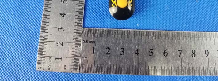
Click to zoom
Application Details
- Equipment Class
- DTS - Digital Transmission System
- Date of Grant
- Oct 20, 2022
- Application Purpose
- Original Equipment
- Date of Application
- Oct 20, 2022
- Equipment Note
- Pocket Auto Catch Lightning
- Frequency Range
- 2402.00000000 - 2480.00000000
- Country
- Taiwan
Documents & Files
Document Text
Text extracted from the exhibit documents filed with the FCC. Open a document above to read the original.
Users Manual
SUPPORT ENGLISH DEUTSCH FRANÇAIS ITALIANO ESPAÑOL ............................................. ............................................. ............................................. ............................................. ............................................. 1 9 17 25 33 Pairing Connection Blue Light flashes Green Light flashes Unpaired ID Paired ID 4. Select Pokémon GO Plus in setting page. Pocket Auto Catch Lightning will start to pair automatically. 3. Tap Settings. 1. Turn on your mobile Bluetooth. 2. Tap the Main Menu. 5. Waiting for pairing. When the Pokémon GO Plus icon turns on, it means pairing is successful. Successful connectionNot connected Connected to Pokémon GO 21 Short press the button to switch between the two function modes. Mode 1: Blue Light Mode 2: Green Light Clear Bluetooth Pairing ID Vibration on / off How to switch between Function Modes Reset to factory settings: 1. Hold button 2. Insert the charger cable and connect to a USB charger port. Function Modes Description Mode 1: Blue Light: Clear Bluetooth Pairing ID Long press the button for 3 seconds Execute clearing ID Green and Red flashing (Please wait 11-20 seconds when clearing ID) Clear Failed (Please re-operate) Clear successful: Blue Light flashes 3 times Clear failed: Red Light flashes 3 times Long press the button for 3 seconds Vibration on: Green Light flashes 3 times Vibration off: Red Light flashes 3 times Mode 2: Green Light: Vibration on / off 3s 43 Situation LED Vibration Others Power / Connection / Other status flashing flashing flashing flashing 3 times Permanently on intermittent White Waiting for connection Low Power No internet connection Items are full Out of Pokéball Pokémon up to maximum/ Far away from Pokéstop ● 0 ~3 minutes: Vibrate 2 times for every 10 seconds. ● 3 ~ 10 minutes: Vibrate 2 times for every 30 seconds. ● Stop warning after 10 minutes. ● If the situation is "Intermittent ", vibrate 3 times instead of 2. ● Vibrate 2 times for every 2 seconds. ● Stop after 3 cycles. When you are playing Pokémon Go, there will be no vibration. (unpaired) (paired) Charge your Device ● When charging Pocket Auto Catch Lightning, 3 colors (red, green, blue) will flash repeatedly. ● When the power is full, Pocket Auto Catch Lightning will display a white light. 65 Warning When it not used over a long period of time, the rechargeable battery may enter the protection mode and cannot be charged smoothly. You can activate the rechargeable battery by pressing and holding the button, then plugging and unplugging the USB charger several times until the white LED flashes, and then releasing the button. Pocket Auto Catch Lightning may fail to pair to device because of the update of Pokémon Go app, or the upgrade of Android and iOS. Pocket Auto Catch Lightning will time out automatically every hour, so players have to reconnect it. Pocket Auto Catch Lightning will time out every 3-5 minutes if the mobile is idle. Better keep it among -20°C ~ 45°C. Suggested charging temperature: 10°C ~ 35°C. Device requires Bluetooth low-energy compatible smartphone with Pokémon GO app installed. Compatible with iPhone 6S or higher devices with iOS Ver. 12 or higher version installed. Compatible with Android devices with 4 GB RAM or more. Bluetooth Smart (Bluetooth Ver. 4.0 or higher) capability and Android Ver. 7.0 or higher version installed. This Product is not sponsored, endorsed, or approved by Nintendo, The Pokémon Company or Niantic. Product Warranty Within one year from purchase date, Brook o ers the product warranty with normal operating circumstances and non-human damage. It includes free maintenance and return. The following conditions are not included in the warranty service: natural disasters, customer induced damage, improper operation, and repaired by non-Brook authorized sta . Please be sure to keep both Warranty card and Retailer invoice. These two documents are necessary to guarantee a return. If the purchase or invoice dates are incorrect or unrecognized, the warranty service is unavailable. Product Name / Product Number *Warranty Period : 1 year Date of Purchase DateMonthYear 87 4. Pokémon GO Plus in den Einstellungen auswählen. Pocket Auto Catch Lightning wird automatisch verbunden. 3. Einstellungen öffnen. 1. Bluetooth des Mobilgeräts einschalten. 2. Hauptmenü öffnen. 5. Wartet auf Verbindung. Wenn das Pokémon GO Plus-Symbol erscheint, war die Verbindung erfolgreich. Verbindung herstellen Blaues Licht blinkt Grünes Licht blinkt ID nicht verbunden ID verbunden Erfolgreich verbundenNicht verbunden Mit Pokémon GO verbunden 109 Kurz auf den Knopf drücken, um zwischen den zwei Modi zu wechseln. Modus 1: Blaues Licht Modus 2: Grünes Licht Bluetooth-Verbindungs- ID entfernen Vibration an/aus Zwischen den Funktionsmodi wechseln Auf Werkseinstellungen zurücksetzen: 1. Knopf gedrückt halten 2. Mit Ladekabel an einen USB-Ladeanschluss anschließen. Beschreibung der Funktionsmodi Modus 1: Blaues Licht: Bluetooth-Verbindungs-ID entfernen Knopf für 3 Sekunden gedrückt halten ID wird entfernt Grünes und rotes Licht blinken (11–20 Sekunden auf das Entfernen der ID warten) Entfernen fehlgeschlagen (Bitte erneut versuchen) Entfernen erfolgreich: Grünes Licht blinkt 3-mal Entfernen fehlgeschlagen: Rotes Licht blinkt 3-mal Knopf für 3 Sekunden gedrückt halten Vibration an: Grünes Licht blinkt 3-mal Modus 2: Grünes Licht: Vibration an/aus 3s Vibration aus: Rotes Licht blinkt 3-mal 1211 Situation LED Vibration Sonstiges Energie/Verbindung/Anderer Status Blinkt Blinkt Blinkt Blinkt 3-mal Leuchtet durchgehend Unregelmäßig Weiß Wartet auf Verbindung Wenig Energie Keine Internetverbindung Rucksack ist voll Keine Pokébälle übrig Maximale Anzahl von Pokémon / PokéStop ist zu weit weg ● 0 ~ 3 Minuten: Vibriert 2-mal alle 10 Sekunden. ● 3 ~ 10 Minuten: Vibriert 2-mal alle 30 Sekunden. ● Keine Warnungen nach 10 Minuten. ● Vibriert 3-mal statt 2-mal, wenn unregelmäßig. ● Vibriert 2-mal alle 2 Sekunden. ● Hört nach 3 …
Text truncated - open the document above for the full version.
External Photos
Page 1 of 4 FCC ID: 2ADKM-ZPP005J IC: 29174-ZPP005J Dongguan Yaxu (AiT) Technology Limited No.22, Jinqianling 3rd Street, Jitigang, Huangjiang, Dongguan, Guangdong, China. External Photos Photo 1 Photo 2 Page 2 of 4 FCC ID: 2ADKM-ZPP005J IC: 29174-ZPP005J Dongguan Yaxu (AiT) Technology Limited No.22, Jinqianling 3rd Street, Jitigang, Huangjiang, Dongguan, Guangdong, China. Photo 3 Photo 4 Page 3 of 4 FCC ID: 2ADKM-ZPP005J IC: 29174-ZPP005J Dongguan Yaxu (AiT) Technology Limited No.22, Jinqianling 3rd Street, Jitigang, Huangjiang, Dongguan, Guangdong, China. Photo 5 Photo 6 Page 4 of 4 FCC ID: 2ADKM-ZPP005J IC: 29174-ZPP005J Dongguan Yaxu (AiT) Technology Limited No.22, Jinqianling 3rd Street, Jitigang, Huangjiang, Dongguan, Guangdong, China. Photo 7 ------End------
ID Label/Location Info
FCC ID Label FCC ID: 2ADKM-ZPP005J IC: 29174-ZPP005J Model:ZPP005J
Internal Photos
Page 1 of 3 FCC ID: 2ADKM-ZPP005J IC : 29174-ZPP005J Dongguan Yaxu (AiT) Technology Limited No.22, Jinqianling 3rd Street, Jitigang, Huangjiang, Dongguan, Guangdong, China. Internal Photos Photo 1 Photo 2 Page 2 of 3 FCC ID: 2ADKM-ZPP005J IC : 29174-ZPP005J Dongguan Yaxu (AiT) Technology Limited No.22, Jinqianling 3rd Street, Jitigang, Huangjiang, Dongguan, Guangdong, China. Photo 3 Photo 4 Antenna Page 3 of 3 FCC ID: 2ADKM-ZPP005J IC : 29174-ZPP005J Dongguan Yaxu (AiT) Technology Limited No.22, Jinqianling 3rd Street, Jitigang, Huangjiang, Dongguan, Guangdong, China. Photo 5 Photo 6 ------End------
RF Exposure Info
RF Exposure evaluation FCC ID: 2ADKM-ZPP005J 1.1. Applicable Standard According to §1.1307(b)(1), systems operating under the provisions of this section shall be operated in a manner that ensures that the public is not exposed to radio frequency energy level in excess of the Commission’s guidelines. According to §1.1310 and §2.1093 RF exposure requirement KDB447498 v06: Mobile and Portable Devices RF Exposure Procedures and Equipment Authorization Policies 1.2. Requirement According to KDB447498 D01 General RF Exposure Guidance v06 Section 4.3.1 Standalone SAR test exclusion considerations: “Unless specifically required by the published RF exposure KDB procedures, standalone 1-g head or body and 10-g extremity SAR evaluation for general population exposure conditions, by measurement or numerical simulation, is not required when the corresponding SAR Test Exclusion Threshold condition, listed below, is satisfied. These test exclusion conditions are based on source-based time-averaged maximum conducted output power of the RF channel requiring evaluation, adjusted for tune-up tolerance, and the minimum test separation distance required for the exposure conditions.22 The minimum test separation distance is determined by the smallest distance from the antenna and radiating structures or outer surface of the device, according to the host form factor, exposure conditions and platform requirements, to any part of the body or extremity of a user or bystander (see 5) of section 4.1). To qualify for SAR test exclusion, the test separation distances applied must be fully explained and justified by the operating configurations and exposure conditions of the transmitter and applicable host platform requirements, typically in the SAR measurement or SAR analysis report, according to the required published RF exposure KDB procedures. When no other RF exposure testing or reporting is required, a statement of justification and compliance must be included in the equipment approval, in lieu of the SAR report, to qualify for the SAR test exclusion. When required, the device specific conditions described in the other published RF exposure KDB procedures must be satisfied before applying these SAR test exclusion provisions; for example, handheld PTT two-way radios, handsets, laptops & tablets etc.23 “ [(max. power of channel, including tune-up tolerance, mW)/ (min. test separation distance, mm)] · [√f (GHz)] ≤ 3.0 for 1-g SAR and ≤ 7.5 for 10-g extremity SAR, where: • f (GHz) is the RF channel transmit frequency in GHz • Power and distance are rounded to the nearest mW and mm before calculation • The result is rounded to one decimal place for comparison • 3.0 and 7.5 are referred to as the numeric thresholds in the step 2 below The test exclusions are applicable only when the minimum test separation distance is ≤ 50 mm and for transmission frequencies between 100 MHz and 6 GHz. When the minimum test separation distance is < 5 mm, a distance of 5 mm according to 5) in section 4.1 is applied to determine SAR test exclusion. Manufacturing tolerance Bluetooth LE GFSK (Peak) 1Mbps Channel LCH MCH HCH Target (dBm) -1 -1 -1 Tolerance ±(dB) 1.0 1.0 1.0 2. Evaluation Result Standalone Antenna 1 RF output power including tune up Band/Mode f (GHz) Antenna Distance (mm) dBm mW SAR Test Exclusion Threshold SAR Test Exclusion Estimated SAR BT 2.5 5 0 1.00 0.316< 3 Yes 0.0422 Remark: 1. Output power including tune up tolerance; 2. When the minimum test separation distance is < 5 mm, a distance of 5 mm according to f) in section 4.1 is applied to determine SAR test exclusion. 3. Conclusion The measurement results comply with the FCC Limit per 47 CFR 2.1093 for the uncontrolled RF Exposure and SAR Exclusion Threshold per KDB 447498 v06, No SAR is required. .....................End.........................
Test Report
Page 1 of 36 Report No.: AIT22092002W1 Dongguan Yaxu (AiT) Technology Limited No.22, Jinqianling 3rd Street, Jitigang, Huangjiang, Dongguan, Guangdong, China. TEST REPORT Client Information: Applicant: Zeroplus Technology Corporation Applicant add.: 3F, No.121, Jian 8th Rd, Chung Ho District New Taipei City, 235, Taiwan Manufacturer: Zeroplus Technology Corporation Manufacturer add.: 3F, No.121, Jian 8th Rd, Chung Ho District New Taipei City, 235, Taiwan Product Information: Product Name: Pocket Auto Catch Lightning Model/HVIN: ZPP005J Brand Name: BROOK FCC ID: 2ADKM-ZPP005J Applicable standards : FCC CFR Title 47 Part 15 Subpart C Section 15.247 Prepared By: Dongguan Yaxu (AiT) Technology Limited No.22, Jinqianling 3rd Street, Jitigang, Huangjiang,Dongguan, Guangdong, China Tel.: +86-769-8202 0499 Fax.: +86-769-8202 0495 Date of Receipt: Sep. 20, 2022 Date of Test: Sep. 20~Sep. 26, 2022 Date of Issue: Sep. 27, 2022 Test Result: Pass This device described above has been tested by Dongguan Yaxu (AiT) Technology Limited and the test results show that the equipment under test (EUT) is in compliance with the FCC requirements. And it is applicable only to the tested sample identified in the report. Note: This report shall not be reproduced except in full, without the written approval of Dongguan Yaxu (AiT) Technology Limited, this document may be altered or revised by Dongguan Yaxu (AiT) Technology Limited, personal only, and shall be noted in the revision of the document. This test report must not be used by the client to claim product endorsement. Reviewed by: Approved by: Simba Huang Seal.chen Page 2 of 36 Report No.: AIT22092002W1 Dongguan Yaxu (AiT) Technology Limited No.22, Jinqianling 3rd Street, Jitigang, Huangjiang, Dongguan, Guangdong, China. 1 Contents Page COVER PAGE 1 CONTENTS...................................................................................................................................................................... 2 2 TEST SUMMARY............................................................................................................................................................ 4 2.1 Statement of the Measurement Uncertainty ................................................................................ 4 2.2 Measurement Uncertainty ........................................................................................................... 4 3 TEST FACILITY............................................................................................................................................................... 5 3.1 Deviation from standard.............................................................................................................. 5 3.2 Abnormalities from standard conditions ...................................................................................... 5 3.3 Test Location............................................................................................................................... 5 4 GENERAL INFORMATION........................................................................................................................................... 6 4.1 Test frequencies.......................................................................................................................... 7 4.2 EUT Peripheral List ..................................................................................................................... 7 4.3 Test Peripheral List ..................................................................................................................... 7 4.4 TEST METHODOLOGY.............................................................................................................. 8 4.4.1 EUT Configuration........................................................................................................................... 8 4.4.2 EUT Exercise .................................................................................................................................. 8 4.4.3 General Test Procedures................................................................................................................. 8 4.5 Description of Test Modes........................................................................................................... 9 5 EQUIPMENT USED DURING TEST.......................................................................................................................... 10 6 TEST RESULTS AND MEASUREMENT DATA...................................................................................................... 11 6.1 Antenna requirement ................................................................................................................ 11 6.2 On Time and Duty Cycle ........................................................................................................... 12 6.3 Maximum Conducted Output Power Measurement .................................................................. 13 6.4 6 dB Spectrum Bandwidth Measurement .................................................................................. 15 6.5 99% Occupy Bandwidth ............................................................................................................16 6.6 Power Spectral Density............................................................................................................. 17 6.7 Conducted Spurious Emissions and Band Edges Test ............................................................. 18 6.8 Restrict-band Band-edge Measurements ................................................................................. 19 6.9 Radiated Emissions Measurement........................................................................................... 22 6.10 Conducted Emissions ............................................................................................................... 33 7 TEST SETUP PHOTOGRAPHS OF EUT...............................…
Text truncated - open the document above for the full version.
Test Report
1 UE/MS OTA Antenna Performance Summary Report UE/MS OTA Antenna Performance Summary Report Prüfbericht-Nr.: Test Report No.: Auftrags-Nr.: Order No.: 238516896 Kunden-Referenz-Nr.: Client Reference No.: N/A Auftragsdatum: Order date: 2021-06-01 Auftraggeber: Client: 孕龍科技股份有限公司 新北市中和區建八路121號3樓 Prüfgegenstand: Test item: 2400 ~ 2500 MHz Bezeichnung / Typ-Nr.: Identification / Type No.: ANT-S Auftrags-Inhalt: Order content: Test Report for Antenna gain Prüfgrundlage: Test specification: Wareneingangsdatum: Date of receipt: 2021-06-01 Prüfmuster-Nr.: Test sample No.: A003064064-001 Prüfzeitraum: Testing period: Ort der Prüfung: Place of testing: Fully Laboratory Taipei Prüflaboratorium: Testing laboratory: Taipei Testing Laboratories Prüfergebnis*: Test result*: Sonstiges / Other: Dieser Prü fbericht bezieht sich nur auf das o.g. Prü fmuster und darf ohne Genehmigung der Prü fstelle nicht auszugsweise vervielfältigt werden. Dieser Bericht berechtigt nicht zur Verwendung eines Prü fzeichens. This test report only relates to the a. m. test sample. Without permission of the test center this test report is not permitted to be duplicated in extracts. This test report does not entitle to carry any test mark. 2 UE/MS OTA Antenna Performance Summary Report 1. Statement of Performance The best results of antenna Performance found during testing for the Sigfox passive antenna are as below : Function Position PK gain (dBi) AVG gain (dBi) Sigfox passive antenna (2400MHz) Free Space -7.06 -12.02 Sigfox passive antenna (2450MHz) Free Space -1.98 -7.04 Sigfox passive antenna (2500MHz) Free Space -6.03 -11.96 2. General Information 2.1 Description of Device Under Test (DUT) Product Feature & Specification DUT Type Sigfox Passive antenna (PCB antenna) Brand Name Zeroplus Model Name ANT-S Type Name Brook-ANT 2.2 Product Photo 3 UE/MS OTA Antenna Performance Summary Report 3. Measurement Environment 3.1 Antenna gain Measurement Setup 4. Photographs of the Test Set-Up EUT=H EUT=E2 4 UE/MS OTA Antenna Performance Summary Report 5. Summary of Test Result 5.1 Test Results of Antenna Pattern Antenna Pattern Result of Frequency 2400MHz(EUT=H,Pol=Horizontal) 5 UE/MS OTA Antenna Performance Summary Report Antenna Pattern Result of Frequency 2400MHz(EUT=H,Pol=Vertical) 6 UE/MS OTA Antenna Performance Summary Report Antenna Pattern Result of Frequency 2400MHz(EUT=E2,Pol=Horizontal) 7 UE/MS OTA Antenna Performance Summary Report Antenna Pattern Result of Frequency 2400MHz(EUT=E2,Pol= Vertical) 8 UE/MS OTA Antenna Performance Summary Report Antenna Pattern Result of Frequency 2450MHz(EUT=H,Pol=Horizontal) 9 UE/MS OTA Antenna Performance Summary Report Antenna Pattern Result of Frequency 2450MHz(EUT=H,Pol=Vertical) 10 UE/MS OTA Antenna Performance Summary Report Antenna Pattern Result of Frequency 2450MHz(EUT=E2,Pol=Horizontal) 11 UE/MS OTA Antenna Performance Summary Report Antenna Pattern Result of Frequency 2450MHz(EUT=E2,Pol= Vertical) 12 UE/MS OTA Antenna Performance Summary Report Antenna Pattern Result of Frequency 2500MHz(EUT=H,Pol=Horizontal) 13 UE/MS OTA Antenna Performance Summary Report Antenna Pattern Result of Frequency 2500MHz(EUT=H,Pol=Vertical) 14 UE/MS OTA Antenna Performance Summary Report Antenna Pattern Result of Frequency 2500MHz(EUT=E2,Pol=Horizontal) 15 UE/MS OTA Antenna Performance Summary Report Antenna Pattern Result of Frequency 2500MHz(EUT=E2,Pol= Vertical)
Test Report
Dongguan Yaxu(AiT) Technology Limited Report No.: AIT22092002W1 FCC ID: 2ADKM-ZPP005J Page 1 of 27 Appendix B RF Test Data for BT (BLE) (Conducted Measurement) Product Name: Pocket Auto Catch Lightning Trade Mark: BROOK Test Model: ZPP005J Environmental Conditions Temperature: 25.5 C Relative Humidity: 52.2% ATM Pressure: 100.0 kPa Test Engineer: Simba Huang Supervised by: Seal Chen Dongguan Yaxu(AiT) Technology Limited Report No.: AIT22092002W1 FCC ID: 2ADKM-ZPP005J Page 2 of 27 Contents Page COVER PAGE 1 Duty Cycle ........................................................................................................................................................................................... 3 1.1 Test Result............................................................................................................................................................................... 3 1.2 Test Graphs ............................................................................................................................................................................. 3 2 Maximum Conducted Output Power ................................................................................................................................................... 3 2.1 Test Result............................................................................................................................................................................... 3 2.2 Test Graphs ............................................................................................................................................................................. 3 3 -6dB Bandwidth ................................................................................................................................................................................... 3 3.1 Test Result............................................................................................................................................................................... 3 3.2 Test Graphs ............................................................................................................................................................................. 3 4 Occupied Channel Bandwidth ............................................................................................................................................................. 3 4.1 Test Result............................................................................................................................................................................... 3 4.2 Test Graphs ............................................................................................................................................................................. 3 5 Maximum Power Spectral Density Level ............................................................................................................................................. 3 5.1 Test Result............................................................................................................................................................................... 3 5.2 Test Graphs ............................................................................................................................................................................. 3 6 Band Edge........................................................................................................................................................................................... 3 6.1 Test Result............................................................................................................................................................................... 3 6.2 Test Graphs ............................................................................................................................................................................. 3 7 Conducted RF Spurious Emission....................................................................................................................................................... 3 7.1 Test Result............................................................................................................................................................................... 3 7.2 Test Graphs ............................................................................................................................................................................. 3 8 Restrict Band ....................................................................................................................................................................................... 3 8.1 Test Result............................................................................................................................................................................... 3 8.2 Test Graphs ............................................................................................................................................................................. 3 Dongguan Yaxu(AiT) Technology Limited Report No.: AIT22092002W1 FCC ID: 2ADKM-ZPP005J Page 3 of 27 1 Duty Cycle 1.1 Test Result Mode Frequency (MHz) Duty Cycle (%) 1/T (kHz) BLE 1M 2402 64.33 2.56 BLE 1M 2440 64 2.56 BLE 1M 2480 64.32 2.56 Dongguan Yaxu(AiT) Technology Limited Report No.: AIT22092002W1 FCC ID: 2ADKM-ZPP005J Page 4 of 27 1.2 Test Graphs Test Graphs BLE 1M 2402MHz BLE 1M 2440MHz Dongguan Yaxu(AiT) Technology Limited Report No.: AIT22092002W1 FCC ID: 2ADKM-ZPP005J Page 5 of 27 BLE 1M 2480MHz Dongguan Yaxu(AiT) Technology Limited Report No.: AIT22092002W1 FCC ID: 2ADKM-ZPP005J Page 6 of 27 2 Maximum Conducted Output Power 2.1 Test Result Mode Frequency (MHz)Conducted Power (dBm) Limit (dBm)Verdict BLE 1M 2402 -1.28 30 Pass BLE 1M 2440 -1.42 30 Pass BLE 1M 2480 -1.72 30 Pass Dongguan Yaxu(AiT) Technology Limited Report No.: AIT22092002W1 F…
Text truncated - open the document above for the full version.
Test Setup Photos
Page 1 of 2 FCC ID: 2ADKM-ZPP005J IC : 29174-ZPP005J Dongguan Yaxu (AiT) Technology Limited No.22, Jinqianling 3rd Street, Jitigang, Huangjiang, Dongguan, Guangdong, China. Test Setup Photo Radiated Emission Page 2 of 2 FCC ID: 2ADKM-ZPP005J IC : 29174-ZPP005J Dongguan Yaxu (AiT) Technology Limited No.22, Jinqianling 3rd Street, Jitigang, Huangjiang, Dongguan, Guangdong, China. Conducted Emission ------End------
Contact Information
Applicant
Tim Huang(Manger)
Test Firm
Dongguan Yaxu (AiT) Technology LimitedCoin Tang
[email protected]+86 0769-82020499-21
Technical Specifications
| # | Rule Parts | Frequency Range | Power Output |
|---|---|---|---|
| 1 | 15C | 2.40 GHz - 2.48 GHz | 700.00 µW |
Other Applications from Zeroplus Technology Corporation
2ADKM006J
Mar 27, 2024Pocket Auto Catch ND
Equipment Class
DTS - Digital Transmission System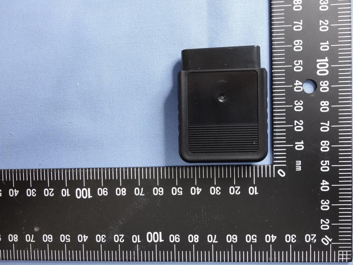
2ADKM0062
Jun 07, 2022BROOK Wingman PS2 Converter
Equipment Class
DSS - Part 15 Spread Spectrum Transmitter
2ADKM005G
Oct 28, 2020X One Adapter SE
Equipment Class
DSS - Part 15 Spread Spectrum Transmitter
2ADKMKM005A
Aug 16, 2020BROOK WingMan-XE Converter
Equipment Class
DSS - Part 15 Spread Spectrum Transmitter
2ADKM005B
Aug 09, 2020BROOK WingMan-SD converter
Equipment Class
DSS - Part 15 Spread Spectrum Transmitter