2ADLV60900138RFID Box
Aquis Wasser-Luft-Systeme GmbH, Lindau, Zweigniederlassung Rebstein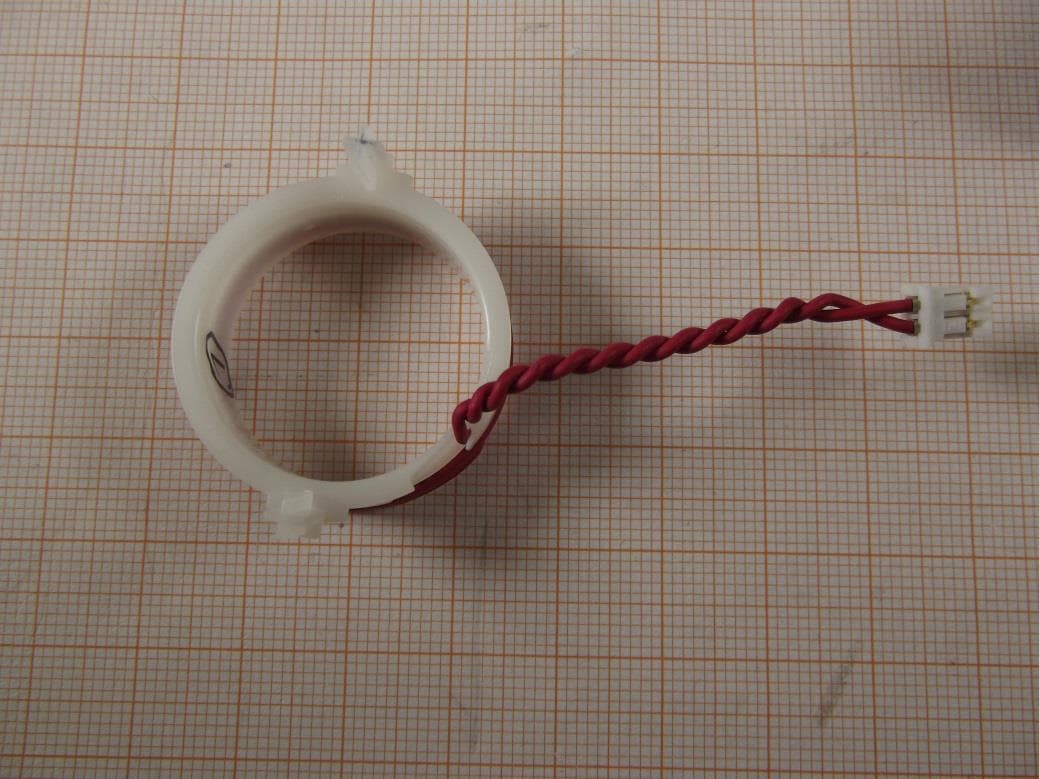
Click to zoom
Application Details
- Equipment Class
- DXX - Part 15 Low Power Communication Device Transmitter
- Date of Grant
- Mar 08, 2015
- Application Purpose
- Original Equipment
- Date of Application
- Mar 08, 2015
- Equipment Note
- RFID Box
- Frequency Range
- 13.56000000 - 13.56000000
- Country
- Switzerland
Documents & Files
Document Text
Text extracted from the exhibit documents filed with the FCC. Open a document above to read the original.
Users Manual
User Manual 1 RFID Module – RFID Box 1JU User / Installation Manual Version 1.0 RFID Module Installation Manual 2 1 BEFORE USAGE ........................................................................................................................... 3 2 SAFETY INSTRUCTIONS ............................................................................................................... 3 3 INSTALLATION REQUIREMENTS ................................................................................................... 3 4 INSTALLATION ............................................................................................................................ 3 4.1 T YPICAL INSTALLATION ........................................................................................................................ 4 5 FIRST USAGE ............................................................................................................................... 5 6 SPECIFICATIONS .......................................................................................................................... 5 6.1 RFID READER TYPE ............................................................................................................................. 5 6.2 INTERFACE ......................................................................................................................................... 5 6.3 S ECURITY .......................................................................................................................................... 5 6.4 USED FREQUENCIES ............................................................................................................................ 5 7 MAXIMUM RATINGS ................................................................................................................... 5 8 RECOMMENDED OPERATING CONDITIONS .................................................................................. 6 9 MODULE REVISION HISTORY ....................................................................................................... 6 10 TROUBLESHOOTING ................................................................................................................ 6 10.1 S YMBOL FOR WORKING RFID MODULE IS MISSING ............................................................................... 6 10.2 SYMBOL FOR WORKING RFID MODULE IS ON BUT IT IS STILL NOT WORKING .............................................. 6 11 FCC / IC ................................................................................................................................... 7 User Manual 3 1 Before usage - Unpack the parts and check for any damages and full content - Read the user manual carefully before first usage Figure 1: RFID antenna and module 1 – RFID antenna 2 – RFID module 2 Safety instructions Well-educated experts must install the RFID module to avoid any damage on the module and the host device. Please contact the manufacturer in case of any problem during the installation! Make sure that the host device is disconnected from the mains during installation to avoid any damage! 3 Installation Requirements • Antenna: Use RFID Antenna 1 JU (Aquis# 60.900.140) only. • Cable length: Maximum length of digital cable is 100cm. Antenna must be directly connected to the module (no extension is allowed). • Module/Antenna placement: distance between module or antenna to human body must be at least 20cm 4 Installation Please follow the instructions below to install the RFID antenna and module in the host device: RFID Module Installation Manual 4 a) Open the machine to access the filter area b) Place the RFID antenna in the machine next to the filter c) Connect the RFID antenna to the module (plug in the 2 pin connector) d) Place the RFID module in the machine next to the RFID antenna e) Connect the RFID module to the machine (plug in the 5 pin connector) f) Make sure that every part is in place and secure them with the plastic clips g) Close the machine Check for proper function after the installation process. 4.1 Typical Installation The pictures below show the typical installation situation in the host device. Figure 2: RFID Antenna and RFID Module Figure 3: Placement below filter and RFID tag RFID Module Installation Manual 5 Figure 4: RFID Antenna and RFID Module connected 5 First usage Make sure that the module is placed correct and all connections are made. Install the filter into the machine and check if the RFID symbol is shown and everything is working correct. In case of any troubles see section 8 ‘Troubleshooting’ or contact the manufacturer for assistance. 6 Specifications 6.1 RFID Reader type Passive RFID Reader with read/write functionality for a variety of passive RFID chips. Frequency Band: 13,56MHz. Air protocol according to ISO 15693 Standard with data transmission speed of 26kbps. 6.2 Interface TTL UART interface (2 Wires: RX, TX) with 9600Baud, No Parity, 8 Data bits, 1 Stop bit, No Handshaking. Proprietary serial protocol with transmission checksum. 6.3 Security Reader supports different levels of security@depending on features of the used RFID Chip@(e.g.: Data locking, Write Password, Mutual Authentication). 6.4 Used frequencies Controller: 8MHz RFID: 13,56MHz 7 Maximum Ratings Parameter min. max. Unit Supply Voltage 0 6 V Voltage on any I/O pin (RxD, TxD, Reset#, ANT1, ANT2) -0,3 1 VCC+0,3 1 V Storage temperature range -40 85 °C Note 1: max. current must be limited to +/- 4mA, if the max. or min. values cannot be respected RFID Module Installation Manual 6 8 Recommended Operating Conditions Parameter min. typ. max. Unit Supply Voltage 5 4,75 5 5,25 V Input low level voltage 1,0 V Input high level voltage 2,3 V Output low level voltage 0,1 4 1,5 3 V Output high level voltage 2,8 3 4,9 4 V Supply current during communication 100 150 mA Supply current in standby mode 2,5 mA Operating temperature range 0 85 °C Electrostatic discharge voltage (Human body model) 14 kV Note 3:…
Text truncated - open the document above for the full version.
External Photos
Test report no.: 1-8637/14-01-01_AnnexA Page 1 of 8 Annex A This test report annex is electronically signed and valid without handwriting signature. For verification of the electronic signatures, the public keys can be requested at the testing laboratory. Test report annex authorised: Stefan Bös Professional Radio Communications & EMC Test report no.: 1-8637/14-01-01_AnnexA Page 2 of 8 External ph ot os o f t he EU T Photo 1: Photo 2: Test report no.: 1-8637/14-01-01_AnnexA Page 3 of 8 Photo 3: Photo 4: Test report no.: 1-8637/14-01-01_AnnexA Page 4 of 8 Photo 5: Photo 6: Test report no.: 1-8637/14-01-01_AnnexA Page 5 of 8 Photo 7: Photo 8: Test report no.: 1-8637/14-01-01_AnnexA Page 6 of 8 Photo 9: Photo 10: Test report no.: 1-8637/14-01-01_AnnexA Page 7 of 8 Photo 11: Test report no.: 1-8637/14-01-01_AnnexA Page 8 of 8 Docu men t his to r y Version Applied changes Date of release Initial release 2014-10-22
ID Label/Location Info
Label and Label location 1 Figure 1: FCC / IC Label Figure 2: Position of Label on module (marked with 2)
Internal Photos
Test report no.: 1-8637/14-01-01_AnnexB Page 1 of 3 Annex B This test report annex is electronically signed and valid without handwriting signature. For verification of the electronic signatures, the public keys can be requested at the testing laboratory. Test report annex authorised: Stefan Bös Professional Radio Communications & EMC Test report no.: 1-8637/14-01-01_AnnexB Page 2 of 3 Inter nal p ho tos of the E UT Photo 1: Photo 2: Test report no.: 1-8637/14-01-01_AnnexB Page 3 of 3 Docu men t his to r y Version Applied changes Date of release Initial release 2014-10-22
Test Report
Page 1 of 23 TEST REPORT Test report no.: 1-8637/14-01-10-A Testing laboratory Applicant CETECOM ICT Services GmbH Untertuerkheimer Strasse 6 – 10 66117 Saarbruecken / Germany Phone: + 49 681 5 98 - 0 Fax: + 49 681 5 98 - 9075 Internet: http://www.cetecom.com e-mail: [email protected] Accredited Testing Laboratory: The testing laboratory (area of testing) is accredited according to DIN EN ISO/IEC 17025 (2005) by the Deutsche Akkreditierungsstelle GmbH (DAkkS) The accreditation is valid for the scope of testing procedures as stated in the accreditation certificate with the registration number: D-PL-12076-01-00 Sanitär Services GmbH Ischlerbahnstrasse 15 5020 Salzburg / AUSTRIA Phone: -/- Fax: +43 662 455 171 Contact: Josef Hofer e-mail: [email protected] Phone: +43 664 24 20 818 Manufacturer Sanitär Services GmbH Ischlerbahnstrasse 15 5020 Salzburg / AUSTRIA Test standard/s 47 CFR Part 15 Title 47 of the Code of Federal Regulations; Chapter I Part 15 - Radio frequency devices RSS - 210 Issue 8 Spectrum Management and Telecommunications - Radio Standards Specification Low-power Licence-exempt Radiocommunication Devices (All Frequency Bands): Category I Equipment For further applied test standards please refer to section 3 of this test report. Test Item Kind of test item: RF-ID 13.56 MHz Model name: RFID BOX 1JU FCC ID: 2ADLV60900138 IC: 12507A-60900138 Frequency: 13.56 MHz Technology tested: RFID Antenna: Loop antenna Power supply: 5.00 V DC Temperature range: 0°C to +85°C This test report is electronically signed and valid without handwriting signature. For verification of the electronic signatures, the public keys can be requested at the testing laboratory. Test report authorised: Test performed: Marco Bertolino Stefan Bös Radio Communications & EMC Radio Communications & EMC Test report no.: 1-8637/14-01-10-A Page 2 of 23 1 Table of contents 1 Table of contents ............................................................................................................................................ 2 2 General information ....................................................................................................................................... 3 2.1 Notes and disclaimer .......................................................................................................................... 3 2.2 Application details ............................................................................................................................... 3 3 Test standard/s ............................................................................................................................................... 3 4 Test environment ............................................................................................................................................ 4 5 Test item .......................................................................................................................................................... 4 5.1 Additional information ........................................................................................................................ 4 6 Test laboratories sub-contracted ................................................................................................................. 4 7 Description of the test setup ......................................................................................................................... 5 7.1 Radiated measurements ..................................................................................................................... 5 7.2 Open area site ...................................................................................................................................... 6 7.3 AC conducted ...................................................................................................................................... 7 8 Summary of measurement results ............................................................................................................... 8 9 Additional comments ..................................................................................................................................... 9 10 Measurement results ............................................................................................................................ 10 10.1 Timing of the transmitter ............................................................................................................... 10 10.2 Field strength of the fundamental ................................................................................................ 12 10.3 99 % emission bandwidth ............................................................................................................. 13 10.4 Field strength of the harmonics and spurious ........................................................................... 14 10.5 Frequency tolerance ...................................................................................................................... 18 10.6 AC line conducted ......................................................................................................................... 19 11 Test equipment and ancillaries used for tests ................................................................................... 21 12 Observations ......................................................................................................................................... 21 Annex A Document history .......................................................................................................................... 22 Annex B Further information ........................................................................................................................ 22 Annex C Accreditation Certificate ............................................................................................................... 23 Test report no.: 1-8637/14-01-10-A Pag…
Text truncated - open the document above for the full version.
Test Setup Photos
Test report no.: 1-8637/14-01-01_AnnexD Page 1 of 4 Annex D This test report annex is electronically signed and valid without handwriting signature. For verification of the electronic signatures, the public keys can be requested at the testing laboratory. Test report annex authorised: Stefan Bös Professional Radio Communications & EMC Test report no.: 1-8637/14-01-01_AnnexD Page 2 of 4 EUT Test se tu p p h otos Photo 1: Photo 2: Test report no.: 1-8637/14-01-01_AnnexD Page 3 of 4 Photo 3: Test report no.: 1-8637/14-01-01_AnnexD Page 4 of 4 Docu men t his to r y Version Applied changes Date of release Initial release 2014-10-22
Contact Information
Applicant
Bernd Heitele(Dr.)
Test Firm
cetecom advanced GmbHGerald Schmidt
Technical Specifications
| # | Rule Parts | Frequency Range | Power Output |
|---|---|---|---|
| 1 | 15C | 13.56 MHz - 13.56 MHz | - |