2ADM5-SP-0770BT FABRIC SPEAKER
Zeeva International Limited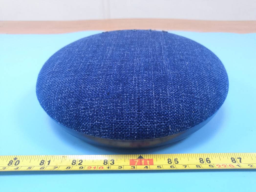
Click to zoom
Application Details
- Equipment Class
- DSS - Part 15 Spread Spectrum Transmitter
- Date of Grant
- May 26, 2020
- Application Purpose
- Original Equipment
- Date of Application
- May 26, 2020
- Equipment Note
- BT FABRIC SPEAKER
- Frequency Range
- 2402.00000000 - 2480.00000000
- Company
- Zeeva International Limited
- Country
- China
Documents & Files
Document Text
Text extracted from the exhibit documents filed with the FCC. Open a document above to read the original.
Users Manual
OFF-ON DC 5V Thank you for purchasing the Revolve Wireless Speaker. This manual provides more information about this wireless speaker, please read the instructions before using. Instruction Manual 1. Use the Micro USB cable provided with this wireless speaker. 2. Connect the Micro USB plug to Micro USB charging port on the speaker, then connect the USB plug to a USB port on a computer or wall adapter to begin charging. 3. The light will turn red while charging and will turn off once fully charged. NOTE: Product Overview Power on Power off Reconnect Wireless speaker to your mobile device 4. You will hear a beep sound when pairing is successful. When powered on, the wireless speaker will automatically connect with the last successfully paired device. Pair Wireless speaker with your mobile device 2. Power on the wireless speaker. 3. Activate the Bluetooth function on your phone within range and select “ BT REVOLVE SPK ” from the list shown. • You must select a qualified charger from a regular manufacturer. • You must charge the Wireless speaker if it has been not used for more than 12 months. Package Contents FAQ Charging your Wireless speaker Technical Specification 1. Keep the distance between your wireless speaker and mobile phone (or other devices) within 32.8 Feet. If the Wireless speaker cannot be paired with your device, please try the following: Ensure that your speaker is in pairing mode or reconnection mode. Ensure that Bluetooth search function of your mobile device is activated. If the Wireless speaker cannot be recharged: If you use a power outlet, ensure that the power supply is connected securely and the outlet works. If you use a computer, ensure that it is connected and the USB port is powered. Slide the ON/OFF switch to the “ON” position. Slide the ON/OFF switch to the “OFF” position. Revolve Wireless Speaker x 1pc Micro USB Charging Cable x 1pc Instruction Manual x 1pc Back Front FCC ID: 2ADM5-SP-0770 -The input voltage to the product is DC 5V 1A. -In order to charge the product in safe manner and reliable conditions, please only adopt certified appropriate charger/ adapter for charging the product. -Only charge the product at ambient temperatures between 10 deg °C/ 50 deg °F and 40 deg °C/104 deg °F. - Do not heat above 70 deg °C/158 deg °F, eg. Do not expose to sunlight or throw into fire. -Switch off the product after use. -Please note that we won’t take any responsibility for any wrong operation (eg. Voltage higher than 5V) as this may result in severe injury or loss of property, and we cannot control the operating process during the time the user using this product. -In extreme cases, abuse or misuse of Lithium battery pack can lead to explosion, heat generation, fire development or smoke development. Safety instructions for the lithium battery and charging the product FCC STATEMENT 1. This device complies with Part 15 of the FCC Rules. Operation is subject to the following two conditions: (1) This device may not cause harmful interference. (2) This device must accept any interference received, including interference that may cause undesired operation. 2. Changes or modifications not expressly approved by the party responsible for compliance could void the user's authority to operate the equipment. NOTE: This equipment has been tested and found to comply with the limits for a Class B digital device, pursuant to Part 15 of the FCC Rules. These limits are designed to provide reasonable protection against harmful interference in a residential installation. This equipment generates uses and can radiate radio frequency energy and, if not installed and used in accordance with the instructions, may cause harmful interference to radio communications. However, there is no guarantee that interference will not occur in a particular installation. If this equipment does cause harmful interference to radio or television reception, which can be determined by turning the equipment off and on, the user is encouraged to try to correct the interference by one or more of the following measures: - Reorient or relocate the receiving antenna. - Increase the separation between the equipment and receiver. - Connect the equipment into an outlet on a circuit different from that to which the receiver is connected. - Consult the dealer or an experienced radio/TV technician for help. RF warning statement: Keep All Relevant Information for Future Reference On/Off Switch Micro USB Charging Port LED Indicator Item#SP-0770 Distributed by 1616 Holdings, Inc. 701 Market Street, Suite 200 Philadelphia, PA 19106 Made in China Driver Diameter: 52 mm Impedance: 4 Ohms Power Supply: Li-ion Battery 3.7V 1200 mAh Play Time: 3 - 3.5 Hours Charging Time: 2 - 2.5 Hours Bluetooth Range: 32.8 Feet Micro USB Charging Cable Included (Plug In) Volume Control Play/PauseNextPrev For your safety, please always use appropriate 5V input charger/ Adapter to charge the product. DO NOT USE Quick Charging USB Adapter to charge the product, as it might damage the product. Product: SP-0770 SKU: Approval:Date: Date: 6 March 2020 SP-0770 S ize: 322.5(w) x 100(h) mm This equipment complies with FCC radiation exposure limits set forth for an uncontrolled environment .This equipment should be installed and operated with minimum distance 20cm between the radiator& your body.
Attestation Statements
Zeeva International Limited Suite 1007B, 10th Floor, Exchange Tower, 33 Wang Chiu Road,Kowloon Bay, Hong Kong Tel: +852-2868 0511 | Fax: +852-2524 1986 E-mail: [email protected] Date: 5/14/2020 To: FEDERAL COMMUNICATIONS COMMISSION Authorization and Evaluation Division 7435 Oakland Mills Road Columbia, MD 21046 We, Zeeva International Limited hereby declare that: Product Name: BT FABRIC SPEAKER Model No: SP-0770 FCC ID: 2ADM5-SP-0770 For BT Mode: BLE 1M/2M are disable by software For Below are activated: Bluetooth BDR(GFSK) , EDR(π/4‐DQPSK), EDR(8DPSK) Except for the manufacturer, the end user does not have any capability to modify/change the RF parameters. We acknowledge that it is the manufacturer’s responsibility to provide the radio configurations to ensure compliance with Commission’s rules. Sincerely Yours, Signature: Printed Name: Akshay P Butani Tiltle: Vice President
Block Diagram
Status LED Blue/Red Bluetooth BK3265 Oscillator 26MHZ Lithium Battery FUS/TVS Over Voltage Speaker1 Micro USB Download&Charge e Antenna 2402-2480MHz LDO 3/1.2/1.8V KEY ON/OFF Charge mamagement Power amplifier[HT8312]2 Power amplifier[HT8312]1 Speaker2
Cover Letter(s)
Zeeva International Limited Suite 1007B, 10th Floor, Exchange Tower, 33 Wang Chiu Road, Kowloon Bay, Hong Kong Tel: +852-2868 0511 | Fax: +852-2524 1986 E-mail: [email protected] FCC Authorization 04/24/2020 FEDERAL COMMUNICATIONS COMMISSIONS Authorization and Evaluation Division 7435 Oakland Mills Road Columbia, MD 21046 Subject: Agent Authorization To whom it may concern: We, Zeeva International Limited the undersigned, hereby authorize Bay Area Compliance Laboratories Corporation to act on its behalf in all matters relating to application for Equipment authorization, including the signing of all documents relating to these matters. All acts carried out by Bay Area Compliance Laboratory Corporation on our behalf shall have the same effect as our own action. We, the undersigned, hereby certify that we are not subject to a denial of federal benefits, that includes FCC benefits, pursuant to Section 5301 of the Anti-Drug Abuse Act of 1988, 21 U.S.C. 862. This authorization is valid until further written notice from the applicant. Sincerely Yours, Signature: Printed Name: Akshay P Butani Title: Vice President QA-FR-170-B
External Photos
EXHIBIT B - EUT EXTERNAL PHOTOGRAPHS Only color different
ID Label/Location Info
EXHIBIT A - FCC ID LABEL AND LOCATION FCC ID Label FCC ID Label Location Information The label shown shall be permanently affixed at a conspicuous location on the device and be readily visible to the user at the time purchase (Labeling requirements per 2.925)
Internal Photos
EXHIBIT C - EUT INTERNAL PHOTOGRAPHS BT Antenna
Operational Description
Circuit Description Battery provides energy for the Bluetooth chip(BK3265 ); Crystal oscillator(26MHz) provides the clock signal for the Bluetooth chip. Products is in broadcasting state when stand by, broadcasting Bluetooth signals according to a certain time interval. Bluetooth signals get through a matching circuit, and then transmitted to the space through the antenna(2402MHz-2480MHz). When the product is connected, the product can be in two-way communication with mobile phones, and then the phone's Bluetooth module sends Bluetooth signals into space, the product receives the Bluetooth signal through an antenna, transmission to the Bluetooth chip via matching circuit.the signal amplifies the audio signal through an amplifier and plays out the audio signal from the TWO speaker
Test Report
Note: Thi agency of with an a s BAC may affec considere d This results sho digital sig Suite is report must n fthe Federal Go sterisk “★”. CL is not respo t test results are d data. s report cannot own in this test gnature may be a e 1007B, 10 Repor Origin Rep R P not be used by th overnment. This onsible for the a e marked with a be reproduced report refer on l available only u Zee 0th Floor, E rt Type: al Report port Numbe Report Dat Reviewed By Prepared By he customer to s report may co authenticity of a an asterisk ’*’. except in full, w ly to the sample under the Adob FCC TE eva Int Exchange To FCC ID r: RSZ20 0 e: 2020-0 5 y: Jimmy RF En g y: Bay A r 6/F., W Buildin Shenzh Tel: +8 Fax: + 8 www.b claim product c ontain data that any test data pro Customer mod without prior w e(s) tested. This be software abov PART ST REP For ernatio ower, 33 W D: 2ADM P r BT 0420830-00 5-12 Xiao gineer rea Complian West Wing, Th ng, Shihua Ro hen, Guangdo 6-755-33320 86-755-3332 aclcorp.co m certification, ap are not covered ovided by the a el name, addres written approval s report is valid ve version 7.0. T 15.247 PORT onal Li ang Chiu R M5-SP-07 roduct Ty T FABRIC nce Laborato hird Phase o oad, Futian F ong, China 0018 0008 m.cn pproval, or endo d by the A2LA applicant. Data i sses, names, tra of the Compan d only with a va 7 imited Road, Kowlo 770 ype: SPEAKER ories Corp. (S f Wanli Indu Free Trade Z orsement by A2 accreditation an included from t ademarks etc. ar ny. Unless other alid digital signa oon Bay, Ho R Shenzhen) ustrial Zone, 2LA* or any nd are marked the applicant th re not rwise stated the ature. The ong Kong hat e Bay Area Compliance Laboratories Corp. (Shenzhen) Report No.: RSZ200420830-00 FCC Part 15.247 Page 2 of 64 TABLE OF CONTENTS GENERAL INFORMATION ....................................................................................................................................... 4 PRODUCT DESCRIPTION FOR EQUIPMENT UNDER TEST (EUT) ..................................................................................... 4 OBJECTIVE ................................................................................................................................................................... 4 RELATED SUBMITTAL(S)/GRANT(S) ............................................................................................................................. 4 TEST METHODOLOGY .................................................................................................................................................. 4 MEASUREMENT UNCERTAINTY .................................................................................................................................... 5 TEST FACILITY ............................................................................................................................................................. 5 SYSTEM TEST CONFIGURATION .......................................................................................................................... 6 DESCRIPTION OF TEST CONFIGURATION ...................................................................................................................... 6 EUT EXERCISE SOFTWARE .......................................................................................................................................... 6 SPECIAL ACCESSORIES ................................................................................................................................................. 6 EQUIPMENT MODIFICATIONS ....................................................................................................................................... 6 SUPPORT EQUIPMENT LIST AND DETAILS .................................................................................................................... 6 EXTERNAL I/O CABLE .................................................................................................................................................. 6 BLOCK DIAGRAM OF TEST SETUP ................................................................................................................................ 7 SUMMARY OF TEST RESULTS ............................................................................................................................... 8 TEST EQUIPMENT LIST ........................................................................................................................................... 9 FCC §15.247 (i) & §2.1091- MAXIMUM PERMISSIBLE EXPOSURE (MPE) ........................................................ 11 APPLICABLE STANDARD ............................................................................................................................................ 11 RESULT ...................................................................................................................................................................... 11 FCC §15.203 – ANTENNA REQUIREMENT .......................................................................................................... 12 APPLICABLE STANDARD ............................................................................................................................................ 12 ANTENNA CONNECTOR CONSTRUCTION .................................................................................................................... 12 FCC §15.207 (a) – AC LINE CONDUCTED EMISSIONS ..................................................................................... 13 APPLICABLE STANDARD ............................................................................................................................................ 13 EUT SETUP ................................................................................................................................................................ 13 EMI TEST RECEIVER SETUP ...................................................................................…
Text truncated - open the document above for the full version.
Test Setup Photos
EXHIBIT D - TEST SETUP PHOTOGRAPHS Conducted Emissions - Front View Conducted Emissions - Side View Radiated Emissions View (Below 1 GHz) Radiated Emissions View (Above 1 GHz)
Contact Information
Applicant
Kevin Tso(Engineering & Compliance Manager)
Test Firm
Bay Area Compliance Laboratories Corp. (Shenzhen)Well Wang
[email protected]+86 (0) 755 33320018
Technical Specifications
| # | Rule Parts | Frequency Range | Power Output |
|---|---|---|---|
| 1 | 15C | 2.40 GHz - 2.48 GHz | 100.00 µW |
Other Applications from Zeeva International Limited
2ADM5-HP-0022
Aug 27, 2026DJ STYLE BT HP F26
Equipment Class
DSS - Part 15 Spread Spectrum Transmitter
2ADM5-SP-0774
Jul 15, 2026DISNEY MICKEY DOME SPKR
Equipment Class
DSS - Part 15 Spread Spectrum Transmitter
2ADM5-ET-0973-27
Jun 04, 2026RC STUNT CAR F26
Equipment Class
DXX - Part 15 Low Power Communication Device Transmitter
2ADM5-GA-0541
Apr 16, 2026LANAS LIFE VGA MOUSE
Equipment Class
DTS - Digital Transmission System
2ADM5-EP-0739
Jan 04, 2026TRANSLATION OWS
Equipment Class
DSS - Part 15 Spread Spectrum Transmitter