2ADM7FSC1-7Paint thickness gauge
FI Test- und Messtechnik GmbH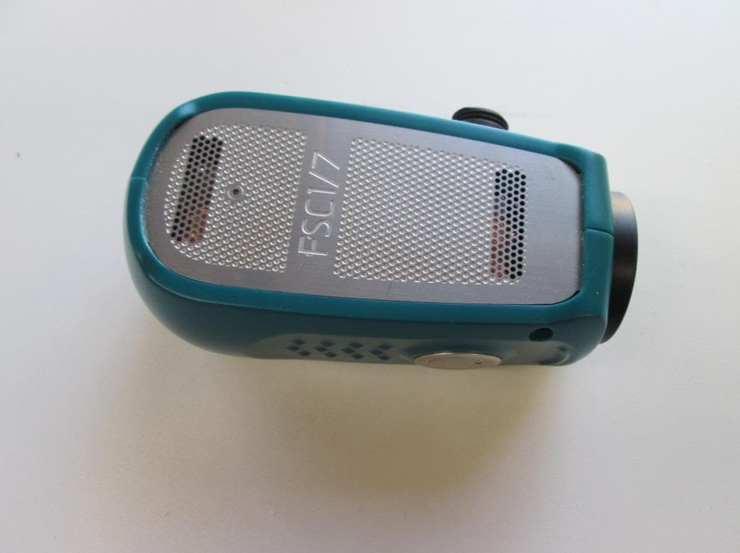
Click to zoom
Application Details
- Equipment Class
- DXX - Part 15 Low Power Communication Device Transmitter
- Date of Grant
- May 10, 2015
- Application Purpose
- Original Equipment
- Date of Application
- May 10, 2015
- Equipment Note
- Paint thickness gauge
- Frequency Range
- 24005.00000000 - 24245.00000000
- Country
- Germany
Documents & Files
Document Text
Text extracted from the exhibit documents filed with the FCC. Open a document above to read the original.
Users Manual
Instruction manual: FSC1/7 2015 March FI Test- und Messtechnik GmbH V2.2 1 Paint thickness gage FSC1/7 Instruction manual 1 Scope of supply Figure 1: Measuring system FSC1/7 Figure 1 shows the measuring system FSC1/7, consisting of a control and display module with a first rechargeable battery pack inside and a belt clip, a hand-held module, a connection cable, a battery charger, a second rechargeable battery pack, a box with calibrations foils, a bag with a headphone, and a case for the equipment. The FSC1/7 is suitable to measure the paint thickness on CFRP without and with lightning protection as well as on metal. Instruction manual: FSC1/7 2015 March FI Test- und Messtechnik GmbH V2.2 2 2 Handling of the battery packs - Plug in a rechargeable battery pack into the control and display module, with the connectors to the top side, see Figure 2. Figure 2: Control and display module - Battery change: Compress the lock at the bottom of the control and display module and pull out the battery pack. - Battery charging: Plug in the rechargeable battery pack into the battery charger. The red LED on the battery charger being on signals the charging procedure and the green LED signals that the battery has full charge. - The charging status of the rechargeable battery pack in use is displayed in the bottom left corner on the control and display module, see Figure 3. The status of charging is given as green from 20 to 100 percent and red for lower than 20 percent. When the status is 0 percent then the control and display module is shutting down. - The charging status is displayed 10 minutes after turning on the display module. 3 How to use the FSC1/7 3.1 Start of the Program - Start the control and display module (press the button on the top). The control LED in the top right corner has to be on. The desktop display will be of the following type. Figure 3: Desktop of control and display module Instruction manual: FSC1/7 2015 March FI Test- und Messtechnik GmbH V2.2 3 - Plug in the connection to the hand-held module at the USB port on the top of the control and display module. - If the connection to the hand-held module was not realized a text according Figure 4 appears. Figure 4: Note to plug-in the hand-held module. - Plug in the connection to the hand-held module. - The connection to the hand-held module is realized, when at the bottom of the display the serial number of the hand module is shown (see Figure 3). Then the system is ready to use. 3.2 General Operating Instructions Generally: The control and display module can be operated by using the touch screen or the keyboard. The touch screen is a resistive touch screen, which also can be used with gloves and a blunt pen. ATTENTION: Do not use sharp objects on the touch screen. Keyboard: - The menu navigation is performed with the arrow “UP” and “DOWN” keys. The key “ENTER” activate the next menu. The key “ESC” activates the last menu. - The number pad of the keyboard is lettered as on the telephone. It can be used e.g. to insert a comment for a measurement or a name for a calibration. Figure 5: Control and display module keyboard - To avoid drift effects let the FSC1/7 warm up for about 15 minutes. Instruction manual: FSC1/7 2015 March FI Test- und Messtechnik GmbH V2.2 4 3.3 Setup - In the menu setup (see Figure 6) you can set the measurement unit “μm” or “mils” in the pull down menu and activate / deactivate the speech output. If headphones are plugged in, the system will speak the measurement results. The headphone connector is on the top of the control and display module. Figure 6: Menu Setup - In the Menu Setup the button “Buzzer output” can be set “on” or “off” for the loud beep which indicates a successful measurement. - In the “Date/Time” menu the date and the time can be set. If you synchronize the data between your computer and the FSC, be aware the time zone of the FSC is UTC. See Figure 7. Figure 7: Menu Date/Time setup - In the menu “Trigger”, see Figure 8, you can set the Trigger option to start the measurement in the following three modes: Button: triggered by the button on the hand-held module Key: triggered by the key 1, key 2 or key 3 of the keyboard on the display module Both: triggered by button or key 1 to 3 Instruction manual: FSC1/7 2015 March FI Test- und Messtechnik GmbH V2.2 5 Figure 8: Menu Trigger - The settings for the lift-off prevention are in the following menus; see Figure 9 to Figure 11. In the menu “Measure count” you can set the number of measurements for the lift-off prevention. If “Measure count” 1 is selected, the lift-off prevention is disabled. Figure 9: Menu Measure count - The duration of one complete measurement is up to one second. This is the minimum time difference between the results of successive measurements. In the menu “Measure delay” you can add a further delay between two single measurements of the lift-off prevention cycle. Figure 10: Menu Measure delay Instruction manual: FSC1/7 2015 March FI Test- und Messtechnik GmbH V2.2 6 - In the menus “Max Delta” you can set the maximal difference between the smallest and largest value of the successive measurements. Figure 11: Menu Max Delta When restarting the control and display module it will always fall back to the factory settings of the lift-off prevention. The following values are set. Measure count: 3 Measure delay: 0 ms Max Delta: 5μm (measure unit μm) / 0.2 mils (measure unit mils) Instruction manual: FSC1/7 2015 March FI Test- und Messtechnik GmbH V2.2 7 3.4 Calibration - In the “Cal” menu you can load and manage existing calibrations and generate new calibrations. Figure 12: Menu Calibration - If you have already a calibration which you want to use, choose “Load Calibration”, select the calibration file and continue with section 3.5 Measuring. - For the use of the system on different substrate materials, the instrument offers a way of calibration by the user. In the “New Calibration” the user has the option to use insulating thickness st…
Text truncated - open the document above for the full version.
External Photos
An n e x 2 t o Test Report # EMCC-140591ABE Page 1 of 4 Issue Date: 2015-04-30 EMCCons DR. RAŠEK GmbH & Co. KG Moggast, Boelwiese 8 91320 Ebermannstadt Germany FCC Registration # 878769 Industry Canada Listing # 3464C 140591ABE Telephone: +49 9194 9016 Telefax: +49 9194 8125 Mail: [email protected] Web: www.emcc.de ANNEX 2 TO TEST REPORT # EMCC-140591ABE, 2015-04-30 EXTERNAL PHOTOGRAPHS OF EUT EQUIPMENT UNDER TEST: Device: FSC1/7 Serial Number: 021 FCC ID: 2ADM7FSC1-7 Equipment Class: Paint thickness gauge Manufacturer: FI Test- und Messtechnik GmbH Address: Breitscheidstraße 17 39114 Magdeburg Germany Phone: +49 391 503894-35 Fax: +49 391 503894-39 RELEVANT STANDARD(S): 47 CFR § 15.249 MEASUREMENT PROCEDURE: ANSI C63.10-2009 RSS-Gen Issue 3 Other An n e x 2 t o Test Report # EMCC-140591ABE Page 2 of 4 Issue Date: 2015-04-30 Test of FI Test- und Messtechnik FSC1/7 to 47 CFR § 15.249 © EMCCons DR. RAŠEK GmbH & Co. KG 2015 140591ABE Photo A2-1: EUT Front view Photo A2-2: Label An n e x 2 t o Test Report # EMCC-140591ABE Page 3 of 4 Issue Date: 2015-04-30 Test of FI Test- und Messtechnik FSC1/7 to 47 CFR § 15.249 © EMCCons DR. RAŠEK GmbH & Co. KG 2015 140591ABE Photo A2-3: Side view with “measure”-button Photo A2-4: Side view with USB-Conector An n e x 2 t o Test Report # EMCC-140591ABE Page 4 of 4 Issue Date: 2015-04-30 Test of FI Test- und Messtechnik FSC1/7 to 47 CFR § 15.249 © EMCCons DR. RAŠEK GmbH & Co. KG 2015 140591ABE Photo A2-5: Top view Photo A2-6: Bottom view with sensor
Internal Photos
An n e x 3 t o Test Report # EMCC-140591ABE Page 1 of 3 Issue Date: 2015-04-30 EMCCons DR. RAŠEK GmbH & Co. KG Moggast, Boelwiese 8 91320 Ebermannstadt Germany FCC Registration # 878769 Industry Canada Listing # 3464C 140591ABE Telephone: +49 9194 9016 Telefax: +49 9194 8125 Mail: [email protected] Web: www.emcc.de ANNEX 3 TO TEST REPORT # EMCC-140591ABE, 2015-04-30 INTERNAL PHOTOGRAPHS OF EUT EQUIPMENT UNDER TEST: Device: FSC1/7 Serial Number: 021 FCC ID: 2ADM7FSC1-7 Equipment Class: Paint thickness gauge Manufacturer: FI Test- und Messtechnik GmbH Address: Breitscheidstraße 17 39114 Magdeburg Germany Phone: +49 391 503894-35 Fax: +49 391 503894-39 RELEVANT STANDARD(S): 47 CFR § 15.249 MEASUREMENT PROCEDURE: ANSI C63.10-2009 RSS-Gen Issue 3 Other An n e x 3 t o Test Report # EMCC-140591ABE Page 2 of 3 Issue Date: 2015-04-30 © EMCCons DR. RAŠEK GmbH & Co. KG 2015 140591ABE Photo A3-1: Opened EUT Photo A3-2: Opened EUT An n e x 3 t o Test Report # EMCC-140591ABE Page 3 of 3 Issue Date: 2015-04-30 © EMCCons DR. RAŠEK GmbH & Co. KG 2015 140591ABE Photo A3-3: Opened EUT Photo A3-4: Opened EUT
Operational Description
Paint thickness gauge FSC1/7 operational description 2015-03-27 Page 1 / 1 The FSC1/7 is suitable to measure the paint thickness (dielectric layer) on CFRP with and without lightning protection as well as on metal. The system consists of a hand-held module and a control and display module (e.g. Laptop or similar device). The hand-held module includes the microwave components. It is intended for measuring a resonant frequency which is determined by a dielectric layer on a base substrate. The main part of the measure system, the resonator, and its application is shown in the picture below. A cylindrical resonant cavity having a circular cylindrical wall and a plane wall on one end thereof, wherein the opposite end is open to be placed up on the dielectric layer on the substrate to form a wall of the resonant cavity on the opposite end. An antenna located within said resonant cavity and adapted to excite an electromagnetic field in the resonant cavity. A reflection meter connected to said antenna and adapted to measure the resonant frequency of the resonant cavity. In this case, the reflection meter is a FMCW Transceiver. The FMCW Transceiver is driven, that only frequencies in the range from 24.005 to 24.245 GHz are adjustable. The Output-Power from the FMCW Transceiver is 10mW. A processor connected to said reflection meter and adapted to determine the resonant frequency of the resonant cavity. The FMCW Transceiver is on constantly whilst power is supplied.
Test Report
lu,Hçs'" Test Report # EMCC-14059148E Page 1 of40 lssue Date:2015-04-30 TEST REPORT # EMCC.I4O59IABE, 2015.04.30 This report replaces Tesú Reporf # EMCC-14059148, 2015-03-25 EQUIPMENT UNDER TEST: Device: FSCI/7 Serial Number: 021 FCC lD: 2ADM7FSC1-7 Application: Paint thickness gauge Manufacturer: Fl Test- und Messtechnik GmbH Address: Breitscheidstraße 17 39114 Magdeburg Germany Phone: +49 391 503894-35 Fax: +49 391 503894-39 RELEVANT STANDARD(S): 47 CFR S 15.249 MEASUREMENT PROGEDURE: X nusl c63.10-2009 ! Rss-cen lssue 3 n other TEST REPORT PREPARED BY: Patrick Reusch EMCCONS DR. RASEK GMbH & CO. KG Moggast, Boelwiese I 91320 Ebermannstadt Germany Phone: +49 9'194 9016 Fax: +4991948125 E-Mail: [email protected] TEST PERSONNEL: HEAD OF COMMERCIAL EMG AND RADIO DEPT.: C /^r4 Patrick Reusch EMCCons oR. RnSex GmbH & Co. KG Moggast, Boelwiese I 91320 Ebermannstadt Germany FCC Registration # 878769 lndustry Canada Listing # 3464C 140591ABE EMC, Raóo, $¡lety åId Enlironrnentrl Tesling Telephone: +49 9194 9016 Telefax: +49I'194 8125 Mail: [email protected] Web: www.emcc.de ( o nhr,.,* Aft kreditierun gsstelle D.FL.12û67,ôr.0t Test Report # EMCC-140591ABE Page 2 of 40 Issue Date: 2015-04-30 Test of FI Test- und Messtechnik FSC1/7 to 47 CFR § 15.249 © EMCCons DR. RAŠEK GmbH & Co. KG 2015 140591ABE CONTENTS Page 1 General Information ................................................................................................................................................................ 3 1.1 Purpose .................................................................................................................................................................... 3 1.2 Limits and Reservations .......................................................................................................................................... 3 1.3 Test Location............................................................................................................................................................ 3 1.4 Manufacturer ............................................................................................................................................................ 3 1.5 Dates and Test Location .......................................................................................................................................... 4 1.6 Ordering Information ............................................................................................................................................... 4 1.7 Climatic Conditions ................................................................................................................................................. 4 2 Product Description ................................................................................................................................................................ 5 2.1 Equipment Under Test (EUT) .................................................................................................................................. 5 2.2 Intended Use ............................................................................................................................................................ 6 2.3 EUT Peripherals/Simulators .................................................................................................................................... 6 2.4 Mode of operation during testing and test set-up ................................................................................................. 7 2.5 Modifications required for compliance .................................................................................................................. 7 3 Test Results Summary ........................................................................................................................................................... 8 4 Power line Conducted Emissions Test ................................................................................................................................. 9 4.1 Regulation ................................................................................................................................................................ 9 4.2 Test Equipment ...................................................................................................................................................... 10 4.3 Test Procedures ..................................................................................................................................................... 10 4.4 Test Result ............................................................................................................................................................. 10 4.5 Measurement Plots ................................................................................................................................................ 12 5 Radiated Emissions 9 kHz – 30 MHz ................................................................................................................................... 13 5.1 Regulation .............................................................................................................................................................. 13 5.2 Test Equipment ...................................................................................................................................................... 14 5.3 Test Procedures ..................................................................................................................................................... 15 5.4 Calculation of Field Strength Limits ..................................................................................................................... 16 5.5 Field Strength Calculation ..................................................................................................................................... 16 5.6 Final Test Results ........…
Text truncated - open the document above for the full version.
Test Setup Photos
An n e x 1 t o Test Report # EMCC-140591ABE Page 1 of 4 Issue Date: 2015-04-30 EMCCons DR. RAŠEK GmbH & Co. KG Moggast, Boelwiese 8 91320 Ebermannstadt Germany FCC Registration # 878769 Industry Canada Listing # 3464C 140591ABE Telephone: +49 9194 9016 Telefax: +49 9194 8125 Mail: [email protected] Web: www.emcc.de ANNEX 1 TO TEST REPORT # EMCC-140591ABE, 2015-04-30 PHOTOGRAPHS OF TEST SET-UP EQUIPMENT UNDER TEST: Device: FSC1/7 Serial Number: 021 FCC ID: 2ADM7FSC1-7 Equipment Class: Paint thickness gauge Manufacturer: FI Test- und Messtechnik GmbH Address: Breitscheidstraße 17 39114 Magdeburg Germany Phone: +49 391 503894-35 Fax: +49 391 503894-39 RELEVANT STANDARD(S): 47 CFR § 15.249 MEASUREMENT PROCEDURE: ANSI C63.10-2009 RSS-Gen Issue 3 Other An n e x 1 t o Test Report # EMCC-140591ABE Page 2 of 4 Issue Date: 2015-04-30 Test of FI Test- und Messtechnik FSC1/7 to 47 CFR § 15.249 © EMCCons DR. RAŠEK GmbH & Co. KG 2015 140591ABE Photo A1-1: Conducted emissions measurement Photo A1-2: Conducted emissions measurement An n e x 1 t o Test Report # EMCC-140591ABE Page 3 of 4 Issue Date: 2015-04-30 Test of FI Test- und Messtechnik FSC1/7 to 47 CFR § 15.249 © EMCCons DR. RAŠEK GmbH & Co. KG 2015 140591ABE Photo A1-3: Radiated emissions measurement at 3 m distance, 9 kHz – 30 MHz Photo A1-4: Radiated emissions measurement at 3 m distance, 30 MHz – 1000 MHz An n e x 1 t o Test Report # EMCC-140591ABE Page 4 of 4 Issue Date: 2015-04-30 Test of FI Test- und Messtechnik FSC1/7 to 47 CFR § 15.249 © EMCCons DR. RAŠEK GmbH & Co. KG 2015 140591ABE Photo A1-5: Radiated emissions measurement at 3 m distance, 1 GHz – 5 GHz Photo A1-6: Sample Photograph of a Prescan at frequencies above 18 GHz
Contact Information
Applicant
Johann Heyen Hinken(Prof. Dr.-Ing.)
Test Firm
EMCCons DR. RASEK GmbH & Co. KGReinhard Sauerchell
Technical Specifications
| # | Rule Parts | Frequency Range | Power Output |
|---|---|---|---|
| 1 | 15C | 24.00 GHz - 24.25 GHz | - |