2ADMJCM1TPContactless Reader
CETRTA POT,d.o.o.,Kranj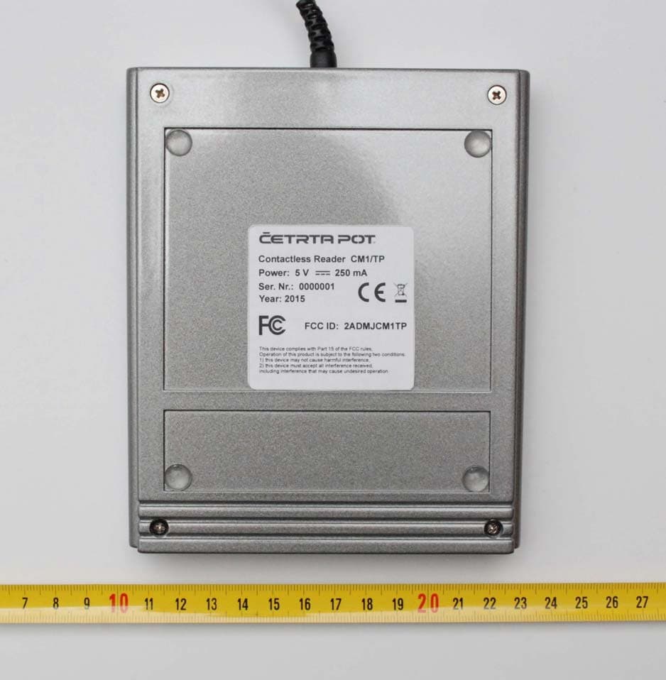
Click to zoom
Application Details
- Equipment Class
- DXX - Part 15 Low Power Communication Device Transmitter
- Date of Grant
- Mar 15, 2015
- Application Purpose
- Original Equipment
- Date of Application
- Mar 12, 2015
- Equipment Note
- Contactless Reader
- Frequency Range
- 13.56000000 - 13.56000000
- Company
- CETRTA POT,d.o.o.,Kranj
- Country
- Slovenia
Documents & Files
Document Text
Text extracted from the exhibit documents filed with the FCC. Open a document above to read the original.
Users Manual
CONTACTLESS READER CM1/TP TECHNICAL DOCUMENTATION PRODUCT SPECIFICATION Version: 1.0.1.0 Date of issue: 19. 01. 2015 CM03/TP/SF Product Specification 2 © ČETRTA POT d.o.o. 2015 Index 1 CONTACTLESS READER CM1/TP - DESCRIPTION ............................... 3 2 TECHNICAL SPECIFICATIONS – CONTACTLESS READER CM1/TP ... 4 3 MAIN SPECIFICATIONS............................................................................ 6 3.1 Hardware ........................................................................................................6 3.2 Software (firmware).......................................................................................6 3.3 Main Parts ......................................................................................................7 3.4 Communication Modes – DIP Switch Settings .........................................12 3.4.1 DIP Switch settings for USB communication mode as keyboard mode................ 12 3.5 USB A- mini B type cable (plug in) ............................................................14 4 SPECIFICATIONS.................................................................................... 15 5 INSTALLING MANUAL............................................................................ 18 5.1 Desktop use .................................................................................................18 5.2 Power supply ...............................................................................................18 6 USER MANUAL .......................................................................................19 6.1 User manual.................................................................................................19 6.2 General user instructions...........................................................................19 6.3 Instuctions for safe work, maintaining and care ......................................20 7 STANDARDS AND COMPATIBILITY...................................................... 21 7.1 ELECTROMAGNETIC COMPATIBILITY .....................................................21 7.1.1 FCC Compliance Statement.................................................................................. 21 7.1.2 COMPLIANCE INFORMATION according to 47CFR 2.1077 ............................... 22 7.1.3 CE Declaration of Conformity ................................................................................ 23 WARRANTY, LIMITATIONS OF LIABILITY................................................... 24 CM03/TP/SF Product Specification 3 © ČETRTA POT d.o.o. 2015 1 CONTACTLESS READER CM1/TP - DESCRIPTION Contactless reader CM1/TP is standalone RFID contactless card reader/writer. It permits working on frequency 13.56 MHz. The reader is an example of implementation of ISO/IEC 14443A (1 – 4 compliant) and ISO/IEC 14443B reader/writer ( Mifare Classic, Desfire EV1). Small size antenna, implemented on the same pcb, permits reading/writing on distance up to 60 mm (13.56 MHz). Contactless reader has two slots for SAM security cards and permits AES and 3DES cryptography. NFCIP-1 mode is supported to. Contactless reader CM1/TP is intended for reading/writing to contactless cards. Reader detects card and confirm reading with sound (beeper) and light (LED) signal. The message with card id and data is sent via USB serial communication to personal computer. Figure 1: CM1/TP contactless reader (front view). CM03/TP/SF Product Specification 4 © ČETRTA POT d.o.o. 2015 2 TECHNICAL SPECIFICATIONS – CONTACTLESS READER CM1/TP Antenna (13,56 MHz) PCB antenna, 70 mm x 70 mm Operating frequency 13.56 MHz Card reading / writing distance Up to 60 mm Contactless card type Mifare, Mifare Classic, Mifare Ultralight, Mifare PLUS, Mifare DESFire EV1 ICODE, P2P passive initiator mode according NFCIP-1 Contactless (RFID) Smart Card Interface ISO 14443A (1 – 4 compliant), data baud rate 848 Kbps (depend on card) ISO 14443B data baud rate 848 Kbps (depend on card) Supports protocol according ISO/IEC 15693, ICODE EPC UID and ISO 18000-3 Mode 3 supports P2P passive mode according ISO/IEC 18092 Embedded firmware Firmware supports use of NFC secure layer Host Interface Host Interface USB 2.0 (also supported USB 1.1) Transmission Speed 12 Mbps (USB 2.0 full speed) Power Supply Bus powered Other Communication Interfaces RS485 serial interface 1 serial interface; RS485 (half duplex), connector type: MKDS 1/8-3,81 terminal clips; communication speed: 115 200 bps (standard) JTAG IEEE1149.1 Serial Interface JTAG 10-pin connector; to connect JTAG adapter Connector Terminal clips MKDS 1/8-3,81 (RS 485 communication, power supply 12V DC, input, output) Settings DIP switch (address, communication, mode) Inputs (model CM03/TP/SF) Keyboard (4 x 3), TTL input inputs (model CM03/TP) TTL input Outputs BICOLOR LED (card reading identification), beeper, transistor output Electrical and Mechanical Specifications Power Supply 5V DC 5%, 250 mA (via USB port) Dimensions (L x W x H) 125 mm x 150 mm x 24 mm Weight approx. 225 g (with USB cable) CM03/TP/SF Product Specification 5 © ČETRTA POT d.o.o. 2015 Operating temperature 0 ... + 40 C (without condensing) Storage temperature -40 ... + 85 C (without condensing) Operating humidity 5 ... 95% RH Certificates and Standards in skladnost Certificate CE, FCC CM03/TP/SF Product Specification 6 © ČETRTA POT d.o.o. 2015 3 MAIN SPECIFICATIONS Contactless reader CM1/TP main hardware and software specifications are described below. 3.1 Hardware Contactless reader CM1/TP main specifications: Permits reading/writing to contactless card on frequency 13,56 MHz. Pcb antenna is integrated in pcb of contactless reader. Permits additional security with use of SAM card (security keys). Integrated communications: USB serial communication (USB 2.0 full speed), serial communication RS485 (option). Communication via JTAG interface (debug) Settings with DIP switch (address, mode, communication, etc). Power supply: 5 V / 250 mA (via USB port). Intended for …
Text truncated - open the document above for the full version.
Block Diagram
ČETRTA POT, D.O.O., Kranj CM1/TP Appendix D: Block Diagram Page 1 of 1 ČETRTA POT, D.O.O., Kranj For more information, visit: http://www.cetrtapot.si Appendix D: Contactless Reader CM1/TP – Block Diagram Picture 1: Contactless Reader CM1/TP - Block Diagram
External Photos
ČETRTA POT, D.O.O., Kranj CM1/TP Appendix A: External Photo Page 1 of 2 ČETRTA POT, D.O.O., Kranj For more information, visit: http://www.cetrtapot.si Appendix A: Contactless Reader CM1/TP – External Photos Picture 1: Contactless Reader CM1/TP - top side ČETRTA POT, D.O.O., Kranj CM1/TP Appendix A: External Photo Page 2 of 2 ČETRTA POT, D.O.O., Kranj For more information, visit: http://www.cetrtapot.si Picture 2: Contactless Reader CM1/TP - bottom side
ID Label/Location Info
ČETRTA POT, D.O.O., Kranj CM1/TP Appendix C: Label & FCC ID Page 1 of 1 ČETRTA POT, D.O.O., Kranj For more information, visit: http://www.cetrtapot.si Appendix C: Contactless Reader CM1/TP – Label and FCC ID Picture 1: Contactless Reader CM1/TP with FCC ID number and label position.
Internal Photos
ČETRTA POT, D.O.O., Kranj CM1/TP Appendix B: Internal Photos Page 1 of 2 ČETRTA POT, D.O.O., Kranj For more information, visit: http://www.cetrtapot.si Appendix B: Contactless Reader CM1/TP – Internal Photos Picture 1: Contactless Reader CM1/TP– internal photo. ČETRTA POT, D.O.O., Kranj CM1/TP Appendix B: Internal Photos Page 2 of 2 ČETRTA POT, D.O.O., Kranj For more information, visit: http://www.cetrtapot.si Picture 2: Contactless Reader CM1/TP (pcb board) – top side. Picture 3: Contactless Reader CM1/TP (pcb board) – bottom side.
Operational Description
Contactless Reader CM1/TP - Operational Description Contactless Reader CM1/TP is an example of implementation of ISO/IEC 14443A and ISO/IEC 14443B reader/writer and NFC reader/writer in desktop housing. PCB antenna, implemented on the same pcb with reader electronics, permits reading/writing on distance up to 60 mm (RFID card or other NFC device). USB serial cable permits communication withi computer. Also powering the reader is via same usb cable from the computer. Main part of Contactless Reader CM1/TP is contactless reader IC CLRC663 in connection with the LPC1768 microcontroller. CLRC663 uses two power supply voltages - 3V3 V and 5 V. All other voltages are generated internally. CLRC663 IC use external quartz (27.12 MHz). All comunication lines (SPI, I2C) are connected to LPC1768 microcontroller. Complementary output stage (TX1, TX2) pins are used to generate output signal for the pcb antenna. Filter stage provide maximum adaption from output stage (CLRC663) to antenna (with matching capacitors). The filter is located near the IC CLRC663. The receiver inputs are connected to pins RXP and RXN. LPC1768 microcontroller with embeded firmware permits reading/writing from/to contactless card or to communicate with the NFC device. On board DIP switches permit reader configuration setting. The default setting is reader in keyboard mode (no extra driver is needed). Communication from reader to personal computer is via usb serial cable. Contactless readers is powered via USB cable – with 5V DC and typical comsumption 250mA.
Operational Description
ČETRTA POT, D.O.O., Kranj CM1/TP Appendix E: Frequencies Page 1 of 1 ČETRTA POT, D.O.O., Kranj For more information, visit: http://www.cetrtapot.si Appendix E: Contactless Reader CM1/TP - Oscillator and PLL Frequencies Oscillator – Frequencies: - CLRC663: 27.120 MHz (Quartz) - Output Frequency (Antenna): 13.56 MHz - LPC1768: 12.00 MHz (Quartz) PLL – Frequencies: none.
Test Report
T251-0097/15 Page: 2 (61) CONTENTS page 1 GENERAL 3 1.1 EQUIPMENT UNDER TEST DESCRITPION 3 1.2 LIST OF MEASUREMENTS PERFORMED 4 1.3 OCCUPIED BANDWIDTH MEASUREMENT 4 1.4 QUASI-PEAK DETECTOR 4 1.5 PEAK, RMS, AND AVERAGE DETECTORS 4 2 LIMITS FOR ALL SUBPARTS 5 2.1 SUBPART C: INTENTIONAL RADIATORS 5 3 ALL TEST EQUIPMENT AND THEIR DESCRIPTION 6 3.1 GENERAL INFORMATION 6 4 GENERAL AND SPECIAL CONDITIONS DESCRIPTION 7 4.1 GENERAL CONDITION DESCRIPTION 7 4.2 SPECIAL CONDITION DESCRIPTION 10 5 TEST SUMMARY 11 5.1 OPERATING VOLTAGES/FREQUENCIES USED FOR TESTING 11 6 EMISSION TESTS 12 6.1 CONDUCTED EMISSION MEASUREMENT (INTENTIONAL RADIATOR) 12 6.2 RADIATED EMISSION MEASUREMENT (INTENTIONAL RADIATOR) 22 6.3 BANDWIDTH OF THE EMISSION (INTENTIONAL RADIATOR) 52 6.4 SPECTRUM MASK (INTENTIONAL RADIATOR) 55 6.5 FREQUENCY TOLERANCE OF THE CARRIER SIGNAL 60 T251-0097/15 Page: 3 (61) 1 GENERAL History sheet Date Report No. Change Revision 2015-03-02 T251-0xxx/15 Initial Test Report issued. -- 1.1 Equipment under test description NOTE: For the testing Contactless card acc. to ISO-14443 type A was used. EUT was connected to a laptop HP, Elitebook 8560p (SIQ No. 107320). Section 15.203, Antenna requirements: Antenna is integrated in the PCB of contactless reader and can not be replaced. Picture of label Product: Contactless reader Type / Model: CM1/TP Supply voltage of transmitter: 5 V dc via USB Protective class: III. Operating frequency: 13,56 MHz Number of channels: 1 Antenna type: PCB antenna, 70 mm x 70 mm Modulation: ASK, Muller coding Hardware version: 3.1 Software version: 1.3.6 FCC ID 2ADMJCM1TP SIQ tested sample number: S20150251 T251-0097/15 Page: 4 (61) 1.2 List of measurements performed PART 15 section Test name 15.207 Conducted emission 15.209 Radiated emission 15.215 Bandwidth of the emission 15.225 Frequency tolerance 1.3 Occupied bandwidth measurement Fundamental frequency Minimum resolution bandwidth 9 kHz to 30 MHz 1 kHz 30 to 1000 MHz 10 kHz 1000 MHz to 40 GHz 100 kHz 1.4 Quasi-peak detector Frequency range Bandwidth (-6dB) 10 Hz to 20 kHz Full range (wideband) 10 kHz to 150 kHz 200 Hz 150 kHz to 30 MHz 9 kHz 30 MHz to 1 GHz 120 kHz 1.5 Peak, rms, and average detectors Frequency range Bandwidth (-6dB) 10 Hz to 20 kHz 10, 100, 1000 Hz 10 kHz to 150 kHz 1 and 10 kHz 150 kHz to 30 MHz 1 and 10 kHz 30 MHz to 1 GHz 10 and 100 kHz 1 GHz to 40 GHz 0.1, 1.0 and 10 MHz T251-0097/15 Page: 5 (61) 2 LIMITS FOR ALL SUBPARTS 2.1 Subpart C: Intentional Radiators 2.1.1 Conducted emission limits: CLASS B limits: Limits (dBμV) Frequency Range (MHz) Quasi-peak Average 0.15 to 0.5 66 – 56* 56 – 46* 0.5 to 5.0 56 46 5.0 to 30.0 60 50 * Decreases with the logarithm of the frequency. The shown limits in table shall not apply to carrier current systems operating as intentional radiators on frequencies below 30 MHz. In lieu thereof, these carrier current systems shall be subject to the following standards: • For carrier current systems containing their fundamental emission within the frequency band 535-1705 kHz and intended to be received using a standard AM broadcast receiver: no limit on conducted emissions. • For all other carrier current systems: 1000 μV within the frequency band 535-1705 kHz, as measured using a 50 μH/50 ohms LISN. • Carrier current systems operating below 30 MHz are also subject to the radiated emission limits as appropriate. 2.1.2 Radiated emission limits: Limits: Limits (dBμV/m) Frequency Range (MHz) VERTICAL HORIZONTAL Test distance (m) 0,009 to 0,490 20*log(2400/F(kHz)) 20*log(2400/F(kHz))300 0,490 to 1,705 20*log(2400/F(kHz)) 20*log(2400/F(kHz))30 1,705 to 30,0 30 30 30 30 to 88 40** 40** 3 88 to 216 43.5** 43.5** 3 216 to 960 46** 46** 3 Above 960 54 54 3 ** Except as provided in paragraph below, fundamental emissions from intentional radiators operating under this section shall not be located in the frequency bands 54-72 MHz, 76-88 MHz, 174-216 MHz or 470-806 MHz. Perimeter protection systems may operate in the 54-72 MHz and 76-88 MHz bands under the provisions of this section. The use of such perimeter protection systems is limited to industrial, business and commercial applications. NOTE: For special limits refer to standard T251-0097/15 Page: 6 (61) 3 ALL TEST EQUIPMENT AND THEIR DESCRIPTION 3.1 General information Description Model No. SIQ No. Last calibration Calibrated until Calibration period Used Rohde-Schwarz, RFI receiver ESU8 105187 2013-10 2015-10 24 months Rohde-Schwarz, RFI receiver ESU26 100428 2014-01 2016-01 24 months X Rohde & Schwarz, Artificial main network ESH2-Z5 106899 2013-05 2015-05 24 months X ETS, Anechoic chamber 3m 103949 2014-11 2016-11 24 months X R&S, Antenna HFH2-Z2 / 2013-09 2015-09 24 months X EMCO, Antenna model 3142 104351 2013-09 2015-09 24 months X EMCO, Antenna model 3115 103002 2013-09 2015-09 24 months X Heinrich Deisel, Turn table DS 420.00 103337 NA NA NA X Kambič, Temperature Chamber I-190 CK 107298 NA NA NA X Fluke, Digital Multimeter 179 106728 2014-06 2015-06 12 month X Antenna tower / / NA NA NA X Controller for turn table and antenna tower / / NA NA NA X T251-0097/15 Page: 7 (61) 4 GENERAL AND SPECIAL CONDITIONS DESCRIPTION 4.1 General condition description Interconnect and power cabling (or wiring) 4.1.1 Test arrangement for conducted emissions Interconnecting cables that hang closer than 40 cm to the ground-plane shall be folded back and forth in the center forming a bundle 30 to 40 cm long. I/O cables that are not connected to a peripheral shall be bundled in the center. The end of the cable may be terminated, if required, using the correct terminating impedance. The overall length shall not exceed 1 m. EUT connected to one LISN. Unused LISN measuring port connectors shall be terminated in 50 Ω. LISN can be placed on top of, or immediately beneath, reference ground-plane. All other equipment powered from additional LISN(s). Multiple outlet strip can be used for multiple power cords of non-EUT equipment. LISN at least 80 cm from neare…
Text truncated - open the document above for the full version.
Test Setup Photos
Annex A of test report T251-xxx/15 Page: 1 (3) Test setup photos Figure 1: Conducted emission test – 150 kHz to 30MHz Figure 2: Radiated emission test – 9kHz to 30MHz Error! Reference source not found. Page: 2 (3) Figure 3: Radiated emission test – 30MHz to 1GHz Figure 4: Radiated emission test – 30MHz to 1GHz Annex A of test report T251-xxx/15 Page: 3 (3) Figure 5: Radiated emission test – 9kHz to 30MHz (retested on a 10 m distance)
Contact Information
Applicant
Tomaz Frelih
Technical Contact
Test Firm
SIQ LjubljanaMarjan Mak
Technical Specifications
| # | Rule Parts | Frequency Range | Power Output |
|---|---|---|---|
| 1 | 15C | 13.56 MHz - 13.56 MHz | - |