2ADQ3ICARUSTXHEAVYICARUS TX HEAVY
ICP Systems B.V.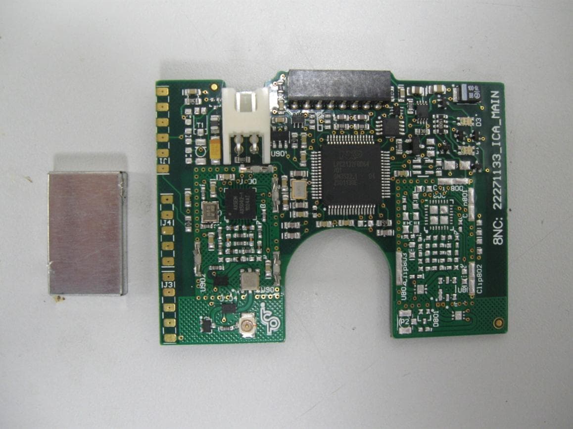
Click to zoom
Application Details
- Equipment Class
- DSR - Part 15 Remote Control/Security Device Transceiver
- Date of Grant
- Feb 17, 2015
- Application Purpose
- Original Equipment
- Date of Application
- Feb 12, 2015
- Equipment Note
- ICARUS TX HEAVY
- Frequency Range
- 433.20000000 - 434.70000000
- Company
- ICP Systems B.V.
- Country
- Netherlands
Documents & Files
Document Text
Text extracted from the exhibit documents filed with the FCC. Open a document above to read the original.
Users Manual
87 ICARUS MANUAL ENGLISH 88 IMPRINT DISTRIBUTION ICP Intelligent Creative Products GmbH Manderscheidtstr. 8b 45141 Essen Germany Tel.: +49(0)201 5367973 MANUFACTURER Intelligent Creative Products bv Ondernemersweg 13 7451 PK Holten Netherlands PRODUCT Item Number: 9237 91xx TX Mini 9237 92tx RX Heavy 9237 93xx TX Heavy 9237 94xx RX Mini 9237 95xx Holders etc. Reference Number: V01 VERSION Datum: 20th September 2010 IMPRINT 89 NL DIRECTIONS CAUTION! Please read the manual carefully before use! The user must have read the manual and fully understood it. In case of questions or if anything is unclear, contact the supplier or the manufacturer before use. The manufacturer cannot monitor observance of these instructions or the conditions of operation and use of the products of the ICARUS family. Incorrect installation and incorrect operation can lead to damage to property and injury. For this reason we do not accept any responsibility or liability for losses, damage to property or personal injury, or any further costs resulting from or in any way associated with incorrect installation, incorrect operation, incorrect use or lacking or incorrect maintenance. SAFETY REGULATIONS I. Products in the ICARUS family must only be installed,maintained, repaired and put into operation by trained and qualified technicians. II. To prevent misuse or danger, never leave the manual devices of the ICARUS family unsupervised. III. When using the manual devices, the work area must be within visual range of the user. DIRECTIONS EN 90 CONTENTS CONTENTS TX MINI94 1.1 Technical data94 1.2 LED status display95 1.3 Operation96 1.4 Changing batteries97 1.5 Cleaning instructions98 1.6 Care and maintenance98 1.7 Transmitter configurations99 1.8 Transmitter fault finding100 1.9 Error codes and repair101 RX MINI102 2.1 Technical data102 2.2 LED status display103 2.3 Commissioning of the receiver104 2.4 Operation104 2.5 Assembly regulations104 2.6 Assembly guidelines105 2.7 Cleaning instructions105 2.8 Care and maintenance105 2.9 Error codes and repair106 2.10 Cable assignment107 2.11 Transmitter logon and logoff108 91 CONTENTS TX HEAVY110 3.1 Technical data110 3.2 LED status display111 3.3 Operation112 3.4 Changing batteries113 3.5 Cleaning instructions114 3.6 Care and maintenance114 3.7 Transmitter fault finding114 RX HEAVY116 4.1 Technical data116 4.2 LED status display118 4.3 Commissioning of the receiver119 4.4 Operation120 4.5 Assembly regulations121 4.6 Assembly guidelines122 4.7 Cleaning instructions123 4.8 Care and maintenance123 4.9 Error codes and repair123 4.10 Cable assignment125 4.11 Transmitter logon and logoff126 EXPLANATION OF SYMBOLS127 DECLARATION OF CONFORMITY128 EN 92 TX MINI 1.1 TECHNICAL DATA Frequency 433MHz Number of channels 6 Number of buttons max. 6 Transmitter output ≤ 10mW Reaction time < 40ms Antenna Internal Batteries 3× Typ AA (normal or rechargeable) IP protection rating IP 67 Dimensions 130 × 54 × 31mm Weight 185g (including batteries) Work area: Range Approx. 100m (depending on surroundings) Temperature -20°C to +50°C (depending on the battery) Air humidity 10% - 95% Working altitude < 2000 m.a.s.l. Housing material PC – ABS Status LED Power LED Battery LED Function key 1 Pushbutton LEDs Function key 2 TX MINI 54 130 31 93 1.2 LED STATUS DISPLAY General: 50ms on off slow flashing normal flashing fast flashing constantly on flash sequence (e. g. 3×) POWER LED (green) off System not active (power switch OFF) constantly on System active (power switch ON) fast flashing Radio signal is being transmitted (key pressed on the transmitter) slow flashing Learning mode active BATTERY LED (red) The speed of flashing depends on the battery status. As the battery voltage decreases the flashing frequency is increased. off Battery OK constantly on Battery is being charged slow flashing Battery voltage below 3V normal flashing Battery voltage below 2.7V fast flashing Battery voltage below 2.4V If the battery voltage falls below 2.1V the remote control switches off automatically. STATUS LED (red) flash sequence Error code (for description see 1.9) PUSHBUTTON LEDs (red) off A function key is not being pressed on The relevant function key is being pressed TX MINI EN 94 1.3 OPERATION I. Ensure the power supply to the receiver (24V DC) II. Push the red „power switch“ on the back of the transmitter up. POWER LED flashes green. III. Press any button on the transmitter IV. Transmitter ready for use (POWER LED CONSTANTLY ON) If the transmitter is not activated for longer than 15 minutes (standard setting) it turns itself off automatically to save energy. To use again, please push the power switch on the back down and start again at point two (see above). Please note: If the transmitter has turned itself off automatically it uses less energy, but still more than when the power switch has been pushed down! If the transmitter is not used for a prolonged period, please remove the batteries to avoid corrosion and resulting damage, and to avoid the batteries losing charge! Power switch down: Power switch up: Transmitter off Transmitter on TX MINI 95 1.4 CHANGING BATTERIES The manual devices in the ICARUS family can be equipped with conventional batteries or rechargeable batteries as desired. A transmitter equipped with rechargeable batteries can be charged at any time with the charger that is available as an accessory. During the charging procedure the BATTERY LED is constantly lit. As soon as it is no longer lit, the rechargeable battery has been charged and is ready for use. To change conventional batteries or rechargeable batteries, proceed as follows: I. Turn the locking screw on the battery compartment anti-clockwise II. Remove the battery compartment cover III. Remove the old batteries IV. Insert 3 AA batteries in the specified direction V. Put on the battery compartment cover and close it VI. Turn the locking screw on the battery compartment clockwise (max. 0.1Nm torque to prevent damage to the housing) I. II. III…
Text truncated - open the document above for the full version.
Cover Letter(s)
SPECIFICATION 22281481b Antenna_TxHV 22281481b Antenna_TxHV Name: J. Keizer Date: 09-08-2011 Check: © ICP B.V. 2011 Page 1 of 6 Index 1. General information ............................................................................................................................................. 1 2. Revision history .................................................................................................................................................... 1 3. Assembly instructions ........................................................................................................................................ 2 4. Silkscreen PCB ..................................................................................................................................................... 5 1. General information Icarus TxHV Antenna assembly 2. Revision history Version Name Date Status / description 22281481 J.K. 16-05-2011 Redesign van 31000970 22281481a H.E. 24-06-2011 Adding extra information to assembly instructions 22281481b H.E. 09-08-2011 Adding silkscreen form PCB for extra assembly information SPECIFICATION 22281481b Antenna_TxHV 22281481b Antenna_TxHV Name: J. Keizer Date: 09-08-2011 Check: © ICP B.V. 2011 Page 2 of 6 3. Assembly instructions SPECIFICATION 22281481b Antenna_TxHV 22281481b Antenna_TxHV Name: J. Keizer Date: 09-08-2011 Check: © ICP B.V. 2011 Page 3 of 6 SPECIFICATION 22281481b Antenna_TxHV 22281481b Antenna_TxHV Name: J. Keizer Date: 09-08-2011 Check: © ICP B.V. 2011 Page 4 of 6 SPECIFICATION 22281481b Antenna_TxHV 22281481b Antenna_TxHV Name: J. Keizer Date: 09-08-2011 Check: © ICP B.V. 2011 Page 5 of 6 4. Silkscreen PCB SPECIFICATION 22281481b Antenna_TxHV 22281481b Antenna_TxHV Name: J. Keizer Date: 09-08-2011 Check: © ICP B.V. 2011 Page 6 of 6 5. Opmerkingen In September 2011 delivery was the inductor placed from datasheet below (datasheet 1) Datasheet 1 Next time, USE THE INDUCTOR from the BOM file
Cover Letter(s)
FCC, Request for non-disclosure Date: 16-Jul-10 RF_501, Issue 6 Page 1 of 1 Company Name: ICP Systems b.v. Address : Handelsweg 48 City: 7451PJ Holten Country: Netherlands To: Telefication B.V., Dept. FCC TCB Edisonstraat 12A 6902 PK ZEVENAAR The Netherlands Subject: Request for confidentiality FCC ID: 2ADQ3ICARUSTXHEAVY Reference number: ###### Dear FCC TCB, 1. Long-Term Confidentiality Pursuant to 47 CFR Section 0.459(a) & (b), we hereby requests non-disclosure and confidential treatment of the following materials submitted in support of FCC certification application: Bill(s) of Material Block Diagrams Operational Description Schematic Diagrams Tune-up Procedure Above materials contain secrets, proprietary and technical information, which would customarily be guarded from competitors under 47 CFR, section 0.457(d)(2). Disclosure or publication or any portion of this company confidential material to other parties could cause substantial competitive harm and provide unjustified benefits for competitors. 2. Short-Term Confidentiality (STC) Pursuant to Public Notice DA 04-1705 of the Commission’s policy, in order to comply with the marketing regulations in 47 CFR §2.803 and the importation rules in 47 CFR §2.1204, a pplicant hereby requests Short-Term Confidential treatment of the following materials (note 1): Internal Photos User’s Manual Test Set-up Photos External Photos Justification: Release of this information prior the availability of the product could cause substantial competitive harm and provide unjustified benefits to competitors. Planned Release Date STC: 180 days (notes 2, 3, 4, 5) Date: 02/06/2015 Name and signature of applicant: Imad Hjije Notes: 1) A document or type of document can only have ONE type of confidentiality! 2) Short-Term confidentiality is in principle for 45 days from date of grant; it can be extended max 3 times (total time 180 days max.)! 3) FCC must be informed when marketing begins earlier. 4) Release takes place automatically thus extension must be requested in time. Telefication does not remind you of this! 5) Request for extension or for release must be received by Telefication at least 7 days before date of actual marketing or before expiration of the STC period
External Photos
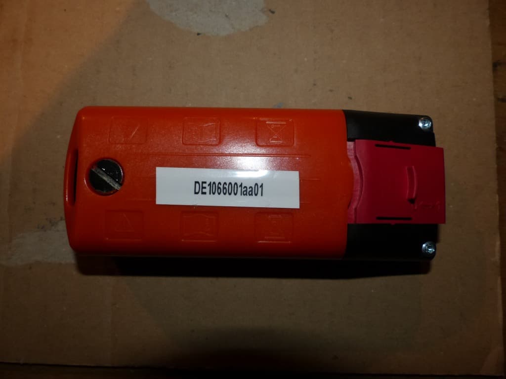
1 Foto's Icarus TxHeavy 2 3 4 5
ID Label/Location Info
1 Label Icarus TxHeavy Icarus Tx Heavy Type: Basic Freq: 433MHz IP54 FCC ID: 2ADQ3ICARUSTXHEAVY
Internal Photos
1 Foto's Icarus TxHeavy 2 3 4 5
Test Report
Test Laboratory: 7Layers AG Borsigstrasse 11 40880 Ratingen Germany Note: The following test results relate only to the devices specified in this document. This report shall not be reproduced in parts without the written approval of the test laboratory. 7 layers AG Aufsichtsratsvorsitzender Registergericht registered in: Borsigstrasse 11 Chairman of the Supervisory Board: Düsseldorf, HRB 44096 40880 Ratingen, Germany Peter Mertel USt-IdNr VAT No.: Phone: +49 (0) 2102 749 0 Vorstand Board: DE 203159652 Fax: +49 (0) 2102 749 350 Dr. H. Ansorge TAX No. 147/5869/0385 www.7Layers.com A Bureau Veritas Group Company FCC Measurement/Technical Report on Icarus TxHeavy Report Reference: MDE_ICPGROUP_1401_FCCa FCC ID: 2ADQ3ICARUSTXHEAVY Test report Reference: MDE_ICPGROUP_1401_FCCa Page 2 of 43 Table of Contents 0 Summary 3 0.1 Technical Report Summary 3 0.2 Measurement Summary 4 1 Administrative Data 5 1.1 Testing Laboratory 5 1.2 Project Data 5 1.3 Applicant Data 5 1.4 Manufacturer Data 5 2 Test object Data 6 2.1 General EUT Description 6 2.2 EUT Main components 7 2.3 Ancillary Equipment 7 2.4 Auxiliary Equipment 7 2.5 EUT Setups 7 2.6 Operating Modes 8 2.7 Product labeling 8 3 Test Results 9 3.1 Duty cycle measurement (based on dwell time measurement) 9 3.2 Spurious radiated emissions 11 3.3 Peak power output 17 3.4 Occupied bandwidth 18 4 Test Equipment 19 5 Photo Report 25 6 Setup Drawings 25 7 Correlation table FCC-IC 26 8 Annex measurement plots 27 8.1 Duty cycle measurement (based on dwell time measurement) 27 8.2 Radiated emissions 29 8.3 Occupation bandwidth 38 Test report Reference: MDE_ICPGROUP_1401_FCCa Page 3 of 43 0 Summary 0.1 Technical Report Summary Type of Authorization Certification for an Intentional Radiator (Periodic operation in the band above 70 MHz) Applicable FCC Rules Edition of FCC Rules: 10-1-13 Prepared in accordance with the requirements of FCC Rules and Regulations as listed in 47 CFR Ch.1 Parts 2 and 15. The following subparts are applicable to the results in this test report. Part 2, Subpart J - Equipment Authorization Procedures, Certification Part 15, Subpart C – Intentional Radiators § 15.201 Equipment authorization requirement § 15.207 Conducted limits § 15.209 Radiated emission limits; general requirements § 15.231 Periodic operation in the band 40.66-40.70 MHz, above 70 MHz Note: none Summary Test Results: The EUT complied with all performed tests as listed in chapter 0.2 Measurement Summary. Test report Reference: MDE_ICPGROUP_1401_FCCa Page 5 of 43 1 Administrative Data 1.1 Testing Laboratory Company Name: 7Layers AG Address Borsigstr. 11 40880 Ratingen Germany This facility has been fully described in a report submitted to the FCC and accepted under the registration number 96716. The test facility is also accredited by the following accreditation organisation: Laboratory accreditation no.: DAkkS D-PL-12140-01-01 Responsible for Accreditation Scope: Dipl.-Ing. Bernhard Retka Dipl.-Ing. Robert Machulec Dipl.-Ing. Andreas Petz Dipl.-Ing. Marco Kullik Report Template Version: 2012-03-14 1.2 Project Data Responsible for testing and report: Dipl.-Ing. Dobrin Dobrinov Date of Test(s): 2014-10-08 to 2014-10-20 Date of Report: 2014-12-11 1.3 Applicant Data Company Name: ICP Systems b.v. Address: Handelsweg 48 7451PJ Holten Netherlands Contact Person: Mr. Philipp Rasche 1.4 Manufacturer Data Company Name: please see applicant data Address: Contact Person: Test report Reference: MDE_ICPGROUP_1401_FCCa Page 6 of 43 2 Test object Data 2.1 General EUT Description Equipment under Test Icarus Type Designation: TxHeavy Kind of Device: (optional) 433 MHz transmitter Voltage Type: DC internal battery Voltage level: 9.0 V Repeated Operation: Manually The EUT is part of a security or safety system: No General product description: The Equipment Under Test (EUT) is a wireless handheld remote control unit transmitter for non-periodic operation in the band above 70 MHz. The operating frequency is in the 433 MHz ISM band. Specific product description for the EUT: None The EUT provides the following ports: Ports - Enclosure The main components of the EUT are listed and described in Chapter 2.2. Test report Reference: MDE_ICPGROUP_1401_FCCa Page 7 of 43 2.2 EUT Main components Type, S/N, Short Descriptions etc. used in this Test Report Short Description Equipment under Test Type Designation Serial No. HW Status SW Status Date of Receipt EUT A (Code: DE10 66000aa01) Icarus TxHeavy 14.000.187 9237930 6 21.047.214 continuous CW/CM (for test purpose only) ‒ Remark: EUT A is equipped with an integral antenna (gain = -16 dBi). NOTE: The short description is used to simplify the identification of the EUT in this test report. 2.3 Ancillary Equipment For the purposes of this test report, ancillary equipment is defined as equipment which is used in conjunction with the EUT to provide operational and control features to the EUT. It is necessary to configure the system in a typical fashion, as a customer would normally use it. But nevertheless Ancillary Equipment can influence the test results. Short Description Equipment under Test Type Designation HW Status SW Status Serial no. FCC ID ‒ ‒ ‒ ‒ ‒ ‒ ‒ 2.4 Auxiliary Equipment For the purposes of this test report, auxiliary equipment is defined as equipment which is used temporarily to enable operational and control features especially used for the tests of the EUT which is not used during normal operation or equipment that is used during the tests in combination with the EUT but is not subject of this test report. It is necessary to configure the system in a typical fashion, as a customer would normally use it. But nevertheless Auxiliary Equipment can influence the test results. Short Description Equipment under Test Type Designation HW Status SW Status Serial no. FCC ID ‒ ‒ ‒ ‒ ‒ ‒ ‒ 2.5 EUT Setups This chapter describes the combination of EUTs and ancillary equipment used for testing. Setup No. Combination of EUTs Description Setup_01 EUT …
Text truncated - open the document above for the full version.
Test Setup Photos
Test Laboratory: 7Layers AG Borsigstrasse 11 40880 Ratingen Germany Note: The following test results relate only to the devices specified in this document. This report shall not be reproduced in parts without the written approval of the test laboratory. 7 layers AG Aufsichtsratsvorsitzender h Registergerichth registered in: Borsigstrasse 11 Chairman of the Supervisory Board: Düsseldorf, HRB 44096 40880 Ratingen, Germany Peter Mertel USt-IdNr h VAT No.: Phone: +49 (0) 2102 749 0 Vorstandh Board: DE 203159652 Fax: +49 (0) 2102 749 350 Dr. H. Ansorge TAX No. 147/5869/0385 www.7Layers.com A Bureau Veritas Group Company Photo Report on Test Setups Report Reference: MDE_ICPGROUP_1401_FCC_Photo_Setups Test report Reference: MDE_ICPGROUP_1401_FCC_Photo_Setups Page 2 of 4 Photo 1: Test setup for radiated measurements (Enclosure, below 30 MHz, intentional radiator §15) Test report Reference: MDE_ICPGROUP_1401_FCC_Photo_Setups Page 3 of 4 Photo 2: Test setup for radiated measurements (Enclosure, semi-anechoic chamber, 30 MHz to 1 GHz, intentional radiator §15) Test report Reference: MDE_ICPGROUP_1401_FCC_Photo_Setups Page 4 of 4 Photo 3: Test setup for radiated measurements (Enclosure, fully-anechoic chamber, above 1 GHz intentional radiator §15)
Contact Information
Applicant
Philipp Rasche
Technical Contact
Non-Technical Contact
ICP Systems b.v.Philipp Rasche
[email protected]31 (0) 548 374 997
Test Firm
7layers AGRobert Machulec
Technical Specifications
| # | Rule Parts | Frequency Range | Power Output |
|---|---|---|---|
| 1 | 15.231 | 433.2 MHz - 434.7 MHz | - |
Other Applications from ICP Systems B.V.
2ADQ3ICARUSTXMINI
Feb 17, 2015ICARUS TX MINI
Equipment Class
DSR - Part 15 Remote Control/Security Device Transceiver