2ADR4202SYard Master
Ming Hong Technology (Shen Zhen) Limited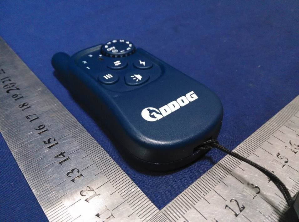
Click to zoom
Application Details
- Equipment Class
- DSR - Part 15 Remote Control/Security Device Transceiver
- Date of Grant
- Jan 21, 2015
- Application Purpose
- Original Equipment
- Date of Application
- Jan 21, 2015
- Equipment Note
- Yard Master
- Frequency Range
- 433.00000000 - 433.00000000
- Country
- China
Documents & Files
Document Text
Text extracted from the exhibit documents filed with the FCC. Open a document above to read the original.
Users Manual
18. FCC Warning This device complies with Part 15 of the FCC Rules. Operation is subject to the following two conditions: (1) this device may not cause harmful interference, and (2) this device must accept any interference received, including interference that may cause undesired operation. Changes or modifications not expressly approved by the party responsible for compliance could void the user's authority to operate the equipment. NOTE: This equipment has been tested and found to comply with the limits for a Class B digital device, pursuant to Part 15 of the FCC Rules. These limits are designed to provide reasonable protection against harmful interference in a residential installation. This equipment generates, uses and can radiate radio frequency energy and, if not installed and used in accordance with the instructions, may cause harmful interference to radio communications. However, there is no guarantee that interference will not occur in a particular installation. If this equipment does cause harmful interference to radio or television reception, which can be determined by turning the equipment off and on, the user is encouraged to try to correct the interference by one or more of the following measures: Reorient or relocate the receiving antenna. Increase the separation between the equipment and receiver. Connect the equipment into an outlet on a circuit different from that to which the receiver is connected. Consult the dealer or an experienced radio/TV technician for help. The device has been evaluated to meet general RF exposure requirement. The device can be used in portable exposure condition without restriction. 1. Using the YARDMASTER202Sfor the First Time When using the DDOG ® YARDMASTER202STraining Collar System for the first time, you should make sure that the receivercollar has been properly paired with the remote transmitter. Test for proper pairing 1. To test whether the pairing between the two devices has been properly configured, switch on the receivercollar by pressing the blue “On/Off” button at the front of the collar. 2. Next, adjust the function dial on the remote transmitter to a position other than OFF and press the toggle button (if required) until the LED light next to the number “1” is switched on to indicate that the remote transmitter will operate at thetransmission frequency of the first paired receiver collar (which by default is the receiver collar that is shipped alongsidethe remote transmitter). 3. Next, press the soundbutton on the remote transmitter and see whether the receiver collar responds with an audible tone signal. Press If an audible tone signal is detected, it means that the two devices have been properly paired. Otherwise, please go through the pairing instructions on page 11to pair the receivercollar with the remote transmitter. 2. Testing the Static Stimulus Function A test light tool is included with the packaging box for the purpose of testing the static stimulus function of the collar. 1. To begin testing, place the test light on top ofthe metal probes as shown below. 2. Then rotate the function dial to a level higher than 2 (otherwise the light emitted will be too weak to notice) and press the static button on the remote transmitter to trigger a static stimulus on the receivercollar. If the static stimulus function is working properly, thetest light will start flashing. Press 3. Fitting and Powering On the Collar The receiver collar should be fitted snuggly across the top of the dog’s neck (as opposed to hanging it loosely at the bottom of the neck), yet loose enough to allow the user to slide one finger inside the strap. The collar casing should be positioned at the front and center of the neck and not rotated to either side. Both of the metal probes underneath the collar unit should be in good contact with the skin as shown below.For dogs with thick coats, it may be necessary to trim the hair underneath the collar unit to ensure that the probes are in good contact with the skin. Once the collar unit has been fitted, trim down the excess strap to a suitable length, if required. The plastic collar strap can be removed and replaced with the spare nylon strap that comes with the packaging. See page13 for detailed instructions on how this is done. Press the blue “On/Off” button at the front of the collar. If a solid green light stays on after momentarily flashingin green and red color, it indicates that the collar is ready for use. 4. Sound/Tone Function The sound button on the remote transmitter is the trigger for a tone signal on the receiver collar. Each time the sound button is pressed, provided that the collar and the remote transmitter are both switched on, a single tone signal will be generated.The collar is pre-set with only one level of tone signal,sounless the function dial has been parked at the OFF position, all other positions on the function dial will generate the same identical tone signal when the sound button has been pressed. If the sound button has been held down, a continuous stream of tone signals will be generated with a short time gap between each tone signal. Press 5. Vibration Function The vibration button on the remote transmitter is the trigger for a vibration response on the receiver collar. Each time the vibration button is pressed, provided that the collar and the remote transmitter are both switched on, a single vibration response will be triggered. The collar is pre-set with only one level of vibration response, so unless the function dial has been parked at the OFF position, all other positions on the function dial will generate the sameidentical vibration response when the vibration button has been pressed.If the vibration button has been held down, a continuous stream of vibration responses will be generated with a short time gap between each vibration response. Press 6. Static Stimulus Function The static stimulus button on the remote transmitter is the trigger for a short static stimulus o…
Text truncated - open the document above for the full version.
Cover Letter(s)
SCS-F18: Project and Product Certification Representative Authorization Letter Page 1 of 1 Rev 5.0 775 Montague Expressway Milpitas, CA 95035 Tel: 408-526-1188 Fax: 408-526-1088 Email: [email protected] Project and Product Certification Representative Authorization Letter Reason for Amendment (current / obsolete) Revision History Approved Date From To Initial Release (obsolete) 1.0 1.0 Nov-14-2006 Revised wording (obsolete) 1.0 2.0 Sept–25-2007 Updated company template (obsolete) 2.0 3.0 Jan-31-2012 Updated letter information (obsolete) 3.0 4.0 May-23-2014 Added FCC ID field (current) 4.0 5.0 Sept 16 2014 SCS-F18: Project and Product Certification Representative Authorization Letter Page 2 of 2 Rev 5.0 Ming Hong Technology (Shen Zhen) Limited 2015-1-19 To: SIEMIC, INC. 775 Montague Expressway, Milpitas, CA 95035 USA Dear Sir/Madam, Re: Product Certification Representative Authorization Letter We, _Ming Hong Technology (Shen Zhen) Limited_hereby authorize SIEMIC, Inc. to act as a Certification Body for certifying for the following project(s): Yard Master, 202S FCC ID: 2ADR4202S Sincerely, signature Martin Kan/ Deputy General Manager E-mail: [email protected] Phone: 0755-86959211 Fax: 0755-86959210 Address: Unit 906, South Block, Resources Tech Building, No.1 Song Ping Shan Road, High-Tech Park, Shenzhen, China.
Cover Letter(s)
SCS-F19: Confidentiality Request Letter Page 1 of 2 Rev 3.0 775 Montague Expressway Milpitas, CA 95035 Tel: 408-526-1188 Fax: 408-526-1088 Email: [email protected] Confidentiality Request Letter Reason for Amendment (current / obsolete) Revision History Approved Date From To Initial Release (obsolete) 1.0 1.0 Nov-14-2006 Adding CFR 2.459 (obsolete) 1.0 2.0 August – 11 - 2008 Updated company template & Added text box (current) 2.0 3.0 Jan-31-2012 SCS-F19: Confidentiality Request Letter Page 2 of 2 Rev 3.0 Ming Hong Technology (Shen Zhen) Limited 2015-1-19 To: Federal Communications Commission Authorization and Evaluation Division 7435 Oakland Mills Road Columbia, MD Subject: Permanent Confidentiality Request for FCC ID: 2ADR4202S We hereby request confidential treatment of information accompanying this application as outlined below: - Block Diagram - Schematics - Operational Description The above materials contain trade secrets and proprietary information not customarily released to the public. The public disclosure of these materials may be harmful to the applicant and provide unjustified benefits to its competitors. The applicant understands that pursuant to Section 0.457 & 0.459 of the Rules, disclosure of this application and all accompanying documentation will not be made before the date of the Grant for this application. Sincerely, signature Martin Kan/ Deputy General Manager E-mail: [email protected] Phone: 0755-86959211 Fax: 0755-86959210 Address: Unit 906, South Block, Resources Tech Building, No.1 Song Ping Shan Road, High-Tech Park, Shenzhen, China.
ID Label/Location Info
Label Location
Internal Photos
Module Antenna
Test Report
TRF No.: FCC 15.231/A Page 1 of 23 Report No.: ES141205064E Ver. 1.0 Access to the World ELECTROMAGNETIC EMISSIONS COMPLIANCE REPORT INTENTIONAL RADIATOR CERTIFICATION TO FCC PART 15 SUBPART C REQUIREMENT T OF Yard Master MODEL No.: 202S Trademark: N/A FCC ID: 2ADR4202S REPORT NO: ES141205064E ISSUE DATE: January 19, 2015 Prepared for MING HONG TECHNOLOGY (SHEN ZHEN) LIMITED Unit 906, South Block, Resources Tech Building, No.1 Song Ping Shan Road, High-Tech Park, Shenzhen, China. Prepared by SHENZHEN EMTEK CO., LTD Bldg 69, Majialong Industry Zone, Nanshan District, Shenzhen, Guangdong, China TEL: 86-755-26954280 FAX: 86-755-26954282 TRF No.: FCC 15.231/A Page 2 of 23 Report No.: ES141205064E Ver. 1.0 Access to the World VERIFICATION OF COMPLIANCE Applicant: MING HONG TECHNOLOGY (SHEN ZHEN) LIMITED Unit 906, South Block, Resources Tech Building, No.1 Song Ping Shan Road, High-Tech Park, Shenzhen, China. Manufacturer: MING HONG TECHNOLOGY (SHEN ZHEN) LIMITED Unit 906, South Block, Resources Tech Building, No.1 Song Ping Shan Road, High-Tech Park, Shenzhen, China. Product Description: Yard Master Model Number: 202S Serial Number: N/A File Number: ES141205064E Date of Test: December 06, 2014 to December 24, 2014 We hereby certify that: The above equipment was tested by SHENZHEN EMTEK CO., LTD. The test data, data evaluation, test procedures, and equipment configurations shown in this report were made in accordance with the procedures given in ANSI C63.4 (2009) and the energy emitted by the sample EUT tested as described in this report is in compliance with radiated emission limits of FCC Rules Part 15.231. The test results of this report relate only to the tested sample identified in this report. Date of Test : December 06, 2014 to December 16, 2014 Prepared by : Jack Li/Editor Reviewer : Joe Xia/Supervisor Approve & Authorized Signer : Lisa Wang/Manager TRF No.: FCC 15.231/A Page 3 of 23 Report No.: ES141205064E Ver. 1.0 Access to the World Table of Contents 1. GENERAL INFORMATION ................................................................................................... 5 1.1. PRODUCT DESCRIPTION ........................................................................................................................ 5 1.2. RELATED SUBMITTAL(S) / GRANT (S) .................................................................................................... 5 1.3. TEST METHODOLOGY ............................................................................................................................. 5 1.4. SPECIAL ACCESSORIES .......................................................................................................................... 5 1.5. EQUIPMENT MODIFICATIONS ................................................................................................................. 5 1.6. MEASUREMENT UNCERTAINTY .............................................................................................................. 6 1.7. TEST FACILITY ........................................................................................................................................ 6 2. SYSTEM TEST CONFIGURATION ..................................................................................... 7 2.1. EUT CONFIGURATION ............................................................................................................................ 7 2.2. EUT EXERCISE ....................................................................................................................................... 7 2.3. TEST PROCEDURE .................................................................................................................................. 7 2.4. DESCRIPTION OF TEST MODES .............................................................................................................. 7 2.5. SUMMARY OF TEST RESULTS ................................................................................................................ 7 2.6. DESCRIPTION OF SUPPORT UNITS ........................................................................................................ 7 3. CONDUCTED EMISSIONS TEST ....................................................................................... 8 3.1. MEASUREMENT PROCEDURE: ............................................................................................................... 8 3.2. TEST SET-UP (BLOCK DIAGRAM OF CONFIGURATION)....................................................................... 8 3.3. MEASUREMENT EQUIPMENT USED: ...................................................................................................... 8 3.4. CONDUCTED EMISSION LIMIT ................................................................................................................ 8 3.5. MEASUREMENT RESULT: ....................................................................................................................... 9 4. RADIATED EMISSION TEST ............................................................................................. 11 4.1. MEASUREMENT PROCEDURE ............................................................................................................... 11 4.2. TEST SET-UP (BLOCK DIAGRAM OF CONFIGURATION)..................................................................... 11 4.3. MEASUREMENT EQUIPMENT USED: .................................................................................................... 12 4.4. RADIATED EMISSION LIMIT ................................................................................................................... 12 4.5. CALCULATION OF AVERAGE FACTOR .................................................................................................. 14 4.6. MEASUREMENT RESULT ...................................................................................................................... 16 5. TRANSMISSION REQUIREMENT .................................................…
Text truncated - open the document above for the full version.
Test Setup Photos
Conducted Measurement Photo Radiated Emission Test
Contact Information
Applicant
Martin Kan(Deputy General Manager)
Test Firm
EMTEK (Shenzhen) Co., Ltd.David Lee
Technical Specifications
| # | Rule Parts | Frequency Range | Power Output |
|---|---|---|---|
| 1 | 15.231 | 433 MHz - 433 MHz | - |