2ADR8GC780736NFC Smart Lock
LEON SPECIALTY INC.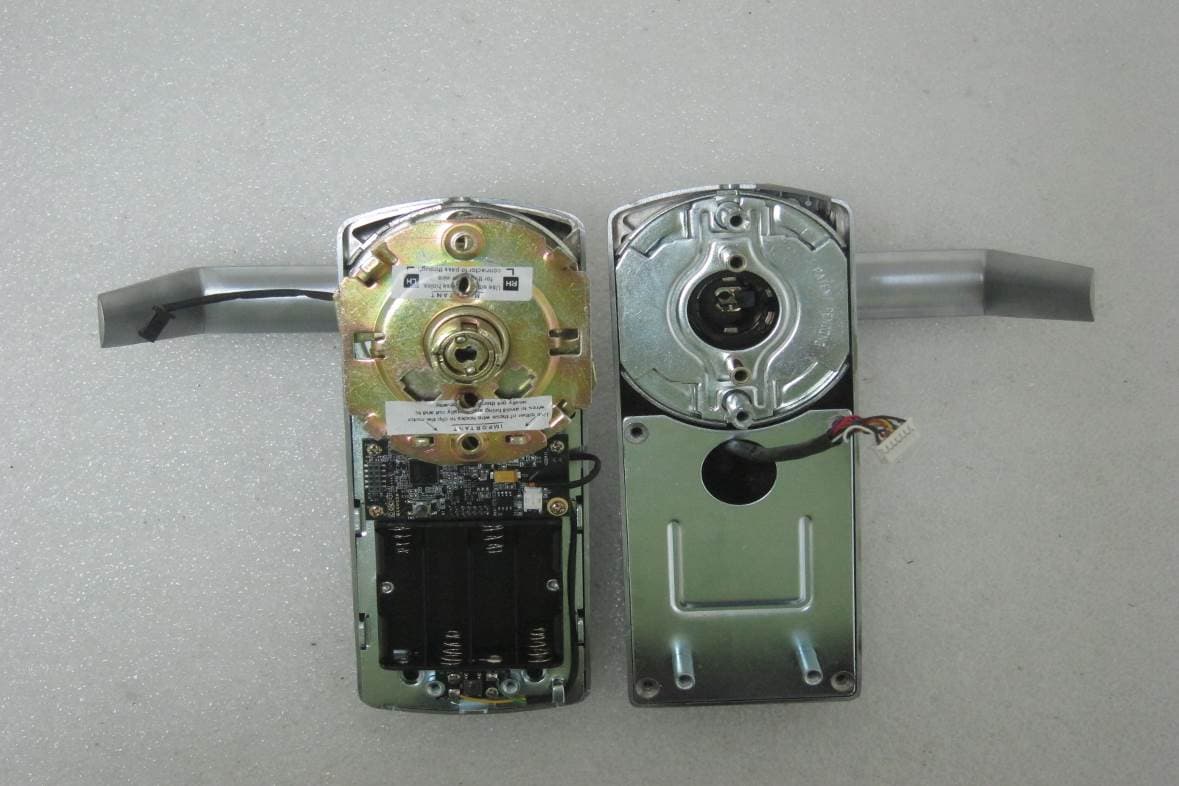
Click to zoom
Application Details
- Equipment Class
- DXX - Part 15 Low Power Communication Device Transmitter
- Date of Grant
- Dec 22, 2014
- Application Purpose
- Original Equipment
- Date of Application
- Dec 21, 2014
- Equipment Note
- NFC Smart Lock
- Frequency Range
- 13.56000000 - 13.56000000
- Company
- LEON SPECIALTY INC.
- Country
- Taiwan
Documents & Files
Document Text
Text extracted from the exhibit documents filed with the FCC. Open a document above to read the original.
Users Manual
PL7000 USER MANUAL REGULATORY COMPLIANCE The device complies with Part 15 of the FCC Rules. Operation is subject to the following two conditions: (1) This device may not cause harmful interference, and (2) This device must accept any interference received, including interference that may cause undesired operation. FCC WARNING STATEMENT You are cautioned that changes or modifications not expressly approved by the part responsible for compliance could void the user’s authority to operate the equipment. This equipment has been tested and found to comply with the limits for a Class B digital device, pursuant to part 15 of the FCC rules. These limits are designed to provide reasonable protection against harmful interference in a residential installation. This equipment generates, uses and can radiate radio frequency energy and, if not installed and used in accordance with the instructions, may cause harmful interference to radio communications. However, there is no guarantee that interference will not occur in a particular installation. If this equipment does cause harmful interference to radio or television reception, which can be determined by turning the equipment off and on, the user is encouraged to try to correct the interference by one or more of the following measures: -Reorient or relocate the receiving antenna. -Increase the separation between the equipment and receiver. -Connect the equipment into an outlet on a circuit different from that to which the receiver is connected. -Consult the dealer or an experienced radio/TV technician for help. 1 TABLE of CONTENTS Introduction ............................................................ 2 Requirement ...................................................... 2 NFC Compatible Smartphone............................ 2 Administrator & Client ...................................... 3 PL7000 Parts ..................................................... 4 User Smartphones .................................................. 6 Install APP ......................................................... 6 Key Butler User Manual .................................... 8 Batch Mode ............................................................ 9 DIN ....................................................................... 10 Low Battery .......................................................... 11 Reset to Factory Default ....................................... 12 Remote Control .................................................... 14 Events and Beeps ................................................. 15 Trouble Shooting .................................................. 16 Specification ......................................................... 17 2 Introduction Requirement You can use smartphones or contactless cards to unlock this lock.The incorporated NFC module allows the PL7000 to be unlocked from NFC compatible smartphones or MIFARE compatible contactless cards. This gives users access easier, safer, and more convenient. NFC Compatible Smartphone PL7000 is designed to communicate with NFC interface, so please choose smartphones which support NFC function to be a client or an administrator. MIFARE Compatible Contactless Card PL7000 can also be unlocked by contactless cards. The cards must be compatible with MIFARE standards. 3 Administrator& Client A NFC smartphone with Key Butler installed, or a contactless card, is called a User. For a User to unlock a lock, it must become a Valid User of the lock. Only Valid Users can unlock the lock. There are two kinds of Valid Users. The first one is Administrator. A lock has only one Administrator at a time. Besides unlock, the Administrator is also responsible for managing the lock and all the Clients. Only smartphones can be used as Administrators. The second kind of Valid Users is Client. A lock can have multiple Clients. A Client can unlock the lock. Both smartphones and contactless cards can be used as Clients. 4 PL7000 Parts Status LED The Status LED indicator located on the head of the lock which indicates the operating status of the lock. Flashing Red LED When an invalid user try to unlock, the status LED will flash red, and generate warning beeps. Flashing Green LED When a Valid user try to unlock, the status LED will flash green, and you’ll hear a unlock beeps. (About beeps, please refer to page 15‘Events and Beeps’) Exterior Status LED Sense Area Keyway 5 Sensing Area NFC is a kind of short distance wireless communication technology. Different smartphones’ NFC antennas may not be at the same location.Please try to find your smartphone’s best sensing area at first. Battery Cover Screw The location of Battery Cover Screw is not only just a screw, but also a Setup Button behind here. Please unload the screw if you want to push the Setup Button. Interior Battery Cover Screw Battery Cover 6 UserSmartphones Whether it’s an administrator or a client, all smartphone usersneed to install the app ‘Key Butler’. Make sure your phone is already connected to internet before installing the app. Install APP Step 1.Open ‘Apps’ group Step 2. Tip ‘Play Store’ Step 3.Search and choose ‘Key Butler’ Step 4.Press ‘INSTALL’ 7 Step 5. After read permissions, click ‘ACCEPT’ Step 6.Tip ‘OPEN’ to start app 8 Key Butler User Manual About how to operate app on smartphone, please refer to the Key Butler user manual. You can find the Key Butler user manual inside the Setting area Or check the web site: http://www.keybutlerapp.com/manual.html 9 Batch Mode For a use-case that only cards are used and no one uses NFC smartphone, the lock provides a method to add/delete cards. 1. Click the Setup button on the inner side of the lock. 2. Before time-out, use a card to tap the lock. The card will become a Client of this lock. All the original clients will be deleted. And the original Administrator will be deleted, either. 3. Upon finish, click the Setup button again to finish the process. Or time-out will terminate the process, too. If there are multipl…
Text truncated - open the document above for the full version.
Users Manual
RS2000 USER MANUAL REGULATORY COMPLIANCE The device complies with Part 15 of the FCC Rules. Operation is subject to the following two conditions: (1) This device may not cause harmful interference, and (2) This device must accept any interference received, including interference that may cause undesired operation. FCC WARNING STATEMENT You are cautioned that changes or modifications not expressly approved by the part responsible for compliance could void the user’s authority to operate the equipment. This equipment has been tested and found to comply with the limits for a Class B digital device, pursuant to part 15 of the FCC rules. These limits are designed to provide reasonable protection against harmful interference in a residential installation. This equipment generates, uses and can radiate radio frequency energy and, if not installed and used in accordance with the instructions, may cause harmful interference to radio communications. However, there is no guarantee that interference will not occur in a particular installation. If this equipment does cause harmful interference to radio or television reception, which can be determined by turning the equipment off and on, the user is encouraged to try to correct the interference by one or more of the following measures: -Reorient or relocate the receiving antenna. -Increase the separation between the equipment and receiver. -Connect the equipment into an outlet on a circuit different from that to which the receiver is connected. -Consult the dealer or an experienced radio/TV technician for help. 1 TABLE of CONTENTS Introduction ............................................................ 2 Requirement ...................................................... 2 NFC Compatible Smartphone............................ 2 Administrator & Client ...................................... 3 RS2000 Parts ..................................................... 4 User Smartphones .................................................. 6 Install APP ......................................................... 6 Key Butler User Manual .................................... 8 Batch Mode ............................................................ 9 DIN ....................................................................... 10 Low Battery .......................................................... 11 Reset to Factory Default ....................................... 12 Events and Beeps ................................................. 14 Trouble Shooting .................................................. 15 Specification ......................................................... 16 2 Introduction Requirement You can use smartphones or contactless cards to unlock this lock.The incorporated NFC module allows the RS2000 to be unlocked from NFC compatible smartphones or MIFARE compatible contactless cards. This gives users access easier, safer, and more convenient. NFC Compatible Smartphone RS2000 is designed to communicate with NFC interface, so please choose smartphones which support NFC function to be a client or an administrator. MIFARE Compatible Contactless Card RS2000 can also be unlocked by contactless cards. The cards must be compatible with MIFARE standards. 3 Administrator& Client A NFC smartphone with Key Butler installed, or a contactless card, is called a User. For a User to unlock a lock, it must become a Valid User of the lock. Only Valid Users can unlock the lock. There are two kinds of Valid Users. The first one is Administrator. A lock has only one Administrator at a time. Besides unlock, the Administrator is also responsible for managing the lock and all the Clients. Only smartphones can be used as Administrators. The second kind of Valid Users is Client. A lock can have multiple Clients. A Client can unlock the lock. Both smartphones and contactless cards can be used as Clients. 4 RS2000 Parts Status LED The Status LED indicator located on the head of the lock which indicates the operating status of the lock. Flashing Red LED When an invalid user try to unlock, the status LED will flash red, and generate warning beeps. Flashing Green LED When a Valid user try to unlock, the status LED will flash green, and you’ll hear a unlock beeps. (About beeps, please refer to page 14 ‘Events and Beeps’) Exterior Status LED Sense Area Keyway 5 Sensing Area NFC is a kind of short distance wireless communication technology. Different smartphones’ NFC antennas may not be at the same location.Please try to find your smartphone’s best sensing area at first. Battery Cover Screw The location of Battery Cover Screw is not only just a screw, but also a Setup Button behind here. Please unload the screw if you want to push the Setup Button. Interior Battery Cover Screw Battery Cover 6 UserSmartphones Whether it’s an administrator or a client, all smartphone usersneed to install the app ‘Key Butler’. Make sure your phone is already connected to internet before installing the app. Install APP Step 1.Open ‘Apps’ group Step 2. Tip ‘Play Store’ Step 3.Search and choose ‘Key Butler’ Step 4.Press ‘INSTALL’ 7 Step 5. After read permissions, click ‘ACCEPT’ Step 6.Tip ‘OPEN’ to start app 8 Key Butler User Manual About how to operate app on smartphone, please refer to the Key Butler user manual. You can find the Key Butler user manual inside the app: Or check the web site: http://www.keybutlerapp.com/manual.html 9 Batch Mode For a use-case that only cards are used and no one uses NFC smartphone, the lock provides a method to add/delete cards. 1. Click the Setup button on the inner side of the lock. 2. Before time-out, use a card to tap the lock. The card will become a Client of this lock. All the original clients will be deleted. And the original Administrator will be deleted, either. 3. Upon finish, click the Setup button again to finish the process. Or time-out will terminate the process, too. If there are multiple cards you want to add, tap them one by one continuously. 10 DIN Correct DIN …
Text truncated - open the document above for the full version.
Cover Letter(s)
SCS-F18: Project and Product Certification Representative Authorization Letter Page 1 of 2 Rev 5.0 775 Montague Expressway Milpitas, CA 95035 Tel: 408-526-1188 Fax: 408-526-1088 Email: [email protected] Project and Product Certification Representative Authorization Letter Reason for Amendment (current / obsolete) Revision History Approved Date From To Initial Release (obsolete) 1.0 1.0 Nov-14-2006 Revised wording (obsolete) 1.0 2.0 Sept–25-2007 Updated company template (obsolete) 2.0 3.0 Jan-31-2012 Updated letter information (obsolete) 3.0 4.0 May-23-2014 Added FCC ID field (current) 4.0 5.0 Sept 16 2014 SCS-F18: Project and Product Certification Representative Authorization Letter Page 2 of 2 Rev 5.0
Cover Letter(s)
SCS-F19: Confidentiality Request Letter Page 1 of 2 Rev 3.0 775 Montague Expressway Milpitas, CA 95035 Tel: 408-526-1188 Fax: 408-526-1088 Email: [email protected] Confidentiality Request Letter Reason for Amendment (current / obsolete) Revision History Approved Date From To Initial Release (obsolete) 1.0 1.0 Nov-14-2006 Adding CFR 2.459 (obsolete) 1.0 2.0 August – 11 - 2008 Updated company template & Added text box (current) 2.0 3.0 Jan-31-2012 SCS-F19: Confidentiality Request Letter Page 2 of 2 Rev 3.0
External Photos
FCC ID: 2ADR8GC780736 International Standards Laboratory Report Number: ISL-14LR306FC EXTERNAL PHOTOGRPHS OF EUT FCC ID: 2ADR8GC780736 International Standards Laboratory Report Number: ISL-14LR306FC EUT 1 PL-7000 EUT 2 PL-7000 FCC ID: 2ADR8GC780736 International Standards Laboratory Report Number: ISL-14LR306FC EUT 3 RS-2000 EUT 4 RS-2000
ID Label/Location Info
FCC ID FORMAT AND LOCATION FCC ID: 2ADR8GC780736 8mm NFC Smart Lock MODEL: PL-7000 FCC ID: 2ADR8GC780736 16mm
ID Label/Location Info
FCC ID FORMAT AND LOCATION FCC ID: 2ADR8GC780736 8mm NFC Smart Lock MODEL: RS-2000 FCC ID: 2ADR8GC780736 16mm
Internal Photos
FCC ID: 2ADR8GC780736 International Standards Laboratory Report Number: ISL-14LR306FC INTERNAL PHOTOGRPHS OF EUT FCC ID: 2ADR8GC780736 International Standards Laboratory Report Number: ISL-14LR306FC EUT 1 EUT 2 FCC ID: 2ADR8GC780736 International Standards Laboratory Report Number: ISL-14LR306FC EUT 3 EUT 4 FCC ID: 2ADR8GC780736 International Standards Laboratory Report Number: ISL-14LR306FC EUT 5 EUT 6
Test Report
Page: 1 of 20 TEST REPORT of FCC Part 15 Subpart C New Application; Class I PC; Class II PC Product : NFC Smart Lock Brand: LEON Model: PL-7000, RS-2000 Model Difference: For different external look FCC ID: 2ADR8GC780736 FCC Rule Part: §15.225, Cat:DXX Applicant: LEON SPECIALTY INC. Address: 7F, No. 95, Minquan Road, Xindian Dist., New Taipei City 23141, Taiwan (R.O.C.) Test Performed by: International Standards Laboratory <Lung-Tan LAB> *Site Registration No. BSMI: SL2-IN-E-0013; MRA TW1036; TAF: 0997; IC: IC4067B-3; *Address: No. 120, Lane 180, San Ho Tsuen, Hsin Ho Rd. Lung-Tan Hsiang, Tao Yuan County 325, Taiwan *Tel : 886-3-407-1718; Fax: 886-3-407-1738 Report No.: ISL-14LR306FC Issue Date : 2014/12/16 Test results given in this report apply only to the specific sample(s) tested and are traceable to national or international standard through calibration of the equipment and evaluating measurement uncertainty herein. This report MUST not be used to claim product endorsement by TAF, NVLAP or any agency of the Government. This test report shall not be reproduced except in full, without the written approval of International Standards Laboratory. -2 of 20- FCC ID: 2ADR8GC780736 International Standards Laboratory Report Number: ISL-14LR306FC VERIFICATION OF COMPLIANCE Applicant: LEON SPECIALTY INC. Product Description: NFC Smart Lock Brand Name: LEON Model No.: PL-7000, RS-2000 Model Difference: For different external look FCC ID: 2ADR8GC780736 Date of test: 2014/12/04 ~ 2014/12/15 Date of EUT Received: 2014/12/04 We hereby certify that: All the tests in this report have been performed and recorded in accordance with the standards described above and performed by an independent electromagnetic compatibility consultant, International Standards Laboratory. The test results contained in this report accurately represent the measurements of the characteristics and the energy generated by sample equipment under test at the time of the test. The sample equipment tested as described in this report is in compliance with the limits of above standards. Test By: Date: 2014/12/16 Dion Chang / Engineer Prepared By: Date: 2014/12/16 Eva Kao / Technical Supervisor Approved By: Date: 2014/12/16 Vincent Su / Technical Manager -3 of 20- FCC ID: 2ADR8GC780736 International Standards Laboratory Report Number: ISL-14LR306FC Version Version No. Date Description 00 2014/12/16 Initial creation of document -4 of 20- FCC ID: 2ADR8GC780736 International Standards Laboratory Report Number: ISL-14LR306FC Table of Contents 1 GENERAL INFORMATION ........................................................................................... 5 1.1 PRODUCT DESCRIPTION ................................................................................................................... 5 1.2 RELATED SUBMITTAL(S) / GRANT (S) .............................................................................................. 6 1.3 TEST METHODOLOGY ....................................................................................................................... 6 1.4 TEST FACILITY ................................................................................................................................. 6 1.5 SPECIAL ACCESSORIES ..................................................................................................................... 6 1.6 EQUIPMENT MODIFICATIONS ........................................................................................................... 6 2 SYSTEM TEST CONFIGURATION .............................................................................. 7 2.1 EUT CONFIGURATION ...................................................................................................................... 7 2.2 EUT EXERCISE ................................................................................................................................. 7 2.3 TEST PROCEDURE ............................................................................................................................. 7 2.4 LIMITATION ...................................................................................................................................... 8 2.5 CONFIGURATION OF TESTED SYSTEM ............................................................................................ 10 3 SUMMARY OF TEST RESULTS ................................................................................. 11 4 DESCRIPTION OF TEST MODES .............................................................................. 11 5 CONDUCTED EMISSIONS TEST ............................................................................... 12 5.1 MEASUREMENT PROCEDURE: ........................................................................................................ 12 5.2 TEST SET-UP (BLOCK DIAGRAM OF CONFIGURATION) ................................................................ 12 5.3 MEASUREMENT EQUIPMENT USED: ............................................................................................... 12 5.4 MEASUREMENT RESULT: ............................................................................................................... 12 6 RADIATED EMISSION TEST ...................................................................................... 13 6.1 MEASUREMENT PROCEDURE.......................................................................................................... 13 6.2 TEST SET-UP (BLOCK DIAGRAM OF CONFIGURATION) ................................................................ 13 6.3 MEASUREMENT EQUIPMENT USED: ............................................................................................... 14 6.4 FIELD STRENGTH CALCULATION ................................................................................................... 14 6.5 MEASUREMENT RESULT ................................................................................................................ 15 7 FREQUENCY TOLERANCE ...................…
Text truncated - open the document above for the full version.
Test Setup Photos
FCC ID: 2ADR8GC780736 International Standards Laboratory Report Number: ISL-14LR306FC PHOTOGRPHS OF SET UP FCC ID: 2ADR8GC780736 International Standards Laboratory Report Number: ISL-14LR306FC Radiated Emission Setup Photos
Contact Information
Applicant
Irvine Liang
Test Firm
International Standards Laboratory Corp.Benson Chen
Technical Specifications
| # | Rule Parts | Frequency Range | Power Output |
|---|---|---|---|
| 1 | 15C | 13.56 MHz - 13.56 MHz | - |