2ADTC-MS05Bluetooth Speaker
YUPENG TECHNOLOGY (HK) CO., LTD.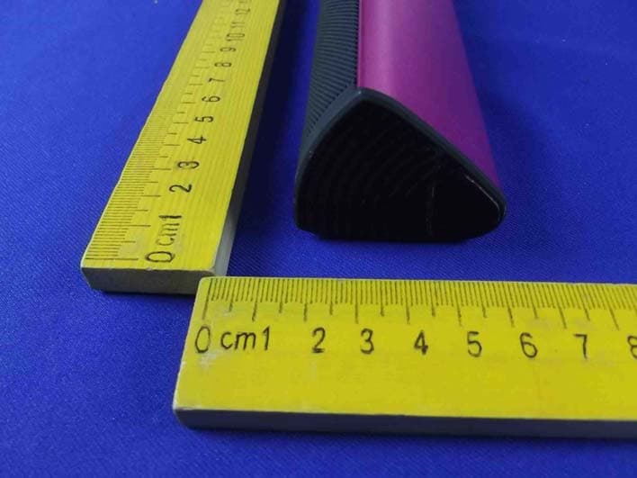
Click to zoom
Application Details
- Equipment Class
- DSS - Part 15 Spread Spectrum Transmitter
- Date of Grant
- Jan 11, 2015
- Application Purpose
- Original Equipment
- Date of Application
- Jan 11, 2015
- Equipment Note
- Bluetooth Speaker
- Frequency Range
- 2402.00000000 - 2480.00000000
- Country
- China
Documents & Files
Document Text
Text extracted from the exhibit documents filed with the FCC. Open a document above to read the original.
Users Manual
FCC STATEMENT : This device complies with Part 15 of the FCC Rules. Operation is subject to the following two conditions: (1) This device may not cause harmful i nterference,and (2) This device must accept any interference received, including interference that may cause : NOTE: This equipment has been tested and found to comply with the limits for a Class B digital device, pursuant to Part 15 of the FCC Rules.These limits are designed to provide Warning approved by the party responsible for compliance could void the user's authority to operate the equipment. :Changes or modifications not expressly undesired operation. reasonable protection against harmful interference in a residential installation. This equipment generates uses and can radiate radio frequency energy and, if not installed and used in accordance with the instructions, may cause harmful interference to radio communications. However, there is no guarantee that interference will not occur in a particular installation. If this equipment does cause harmful interference to radio or television reception, which can be determined by turning the equipment off and on, the user is encouraged to try to correct the interference by one or more of the following measures: Reorient or relocate the receiving antenna. Increase the separation between the equipment and receiver. Connect the equipment into an outlet on a circuit different from that to which the receiver : RF warning statement: is connected. Consult the dealer or an experienced radio/TV technician for help. The device has been evaluated to meet general RF exposure requirement. The device can be used in portable exposure condition without restriction. .
External Photos
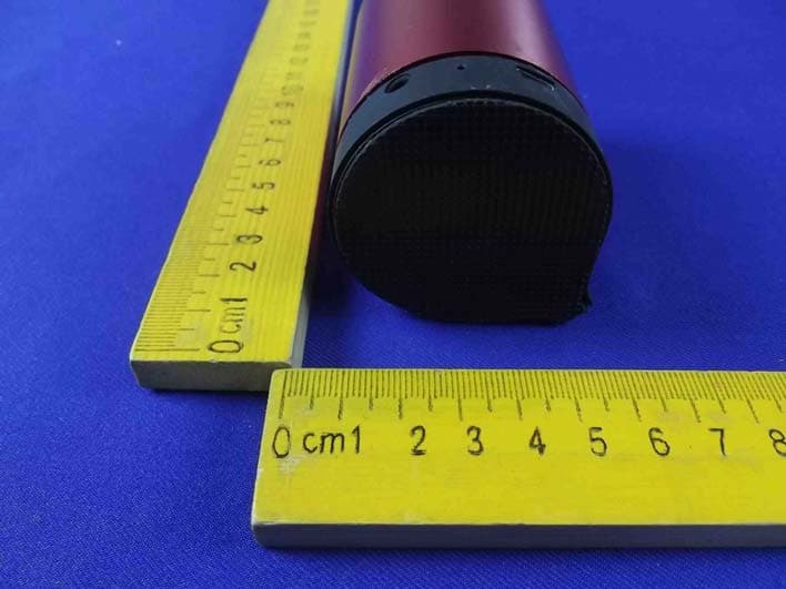
Figure 1 The EUT-Top View Figure 2 The EUT-Bottom View Figure 3 The EUT-Front View Figure 4 The EUT-Right View Figure 5 The EUT-Left View
ID Label/Location Info
This device complies with Part 15 of the FCC Rules. Operation is subject to the following two conditions: 1. This device may not cause harmful interference, and 2. This device must accept any interference received, including interference that may cause undesired operation.
Internal Photos
Figure 6 TheEUT-InsideView Figure 7 PCB of the EUT-Front View Figure 8 PCB of the EUT-Back View Figure 9 PCB of the EUT-Front View Antenna Figure 10 PCB of the EUT-Back View
Test Report
Shenzhen Anbotek Compliance Laboratory Limited FCC ID: 2ADTC-MS05 Page 1 of 56 Report No.: R011409475E Shenzhen Anbotek Compliance Laboratory Limited Tel:(86)755-26066544 Fax:(86)755-26014772 www.anbotek.com FCC TEST REPORT for YUPENG TECHNOLOGY (HK) CO., LTD. Bluetooth Speaker Model No.: MS05 Report Number:R011409475E Date of Test:Sept. 26~Nov. 14, 2014 Date of Report:Dec. 18, 2014 Prepared fo r:YUPENG TECHNOLOGY (HK) CO., LTD. Address:#708, Jialingyu Gongmao Building, Dapu North Road, Houting Community, Shajing Town, Baoan District, Shenzhen, China Prepared By:Shenzhen Anbotek Compliance Laboratory Limited Address:1/F., Building 1, SEC Industrial Park, No.0409 Qianhai Road, Nanshan District, Shenzhen, Guangdong, China Tel: (86) 755-26066544 Fax: (86) 755-26014772 Shenzhen Anbotek Compliance Laboratory Limited FCC ID: 2ADTC-MS05 Page 2 of 56 Report No.: R011409475E Shenzhen Anbotek Compliance Laboratory Limited Tel:(86)755-26066544 Fax:(86)755-26014772 www.anbotek.com TABLE OF CONTENTS Description Page Test Report 1. GENERAL INFORMATION......................................................................................................5 1.1 Description of Device (EUT).................................................................................................................5 1.2 Auxiliary Equipment Used during Test................................................................................................. 6 1.3 Description of Test Facility................................................................................................................... 6 1.4 Measurement Uncertainty......................................................................................................................6 2. TEST PROCEDURE....................................................................................................................7 3. CONDUCTED EMISSION TEST.............................................................................................. 8 3.1 Block Diagram of Test Setup.................................................................................................................8 3.2 Power Line Conducted Emission Measurement Limits (15.207)..........................................................8 3.3 Configuration of EUT on Measurement................................................................................................ 8 3.4 Operating Condition of EUT................................................................................................................. 8 3.5 Test Procedure....................................................................................................................................... 9 3.6 Test equipment.......................................................................................................................................9 3.7 Power Line Conducted Emission Measurement Results....................................................................... 9 4. RADIATION INTERFERENCE.............................................................................................. 12 4.1 Requirements (15.247, 15.209):...........................................................................................................12 4.2 Test Procedure..................................................................................................................................... 12 4.3 Test Configuration............................................................................................................................... 13 4.4 Test Results..........................................................................................................................................14 5. CHANNEL SEPARATION TEST............................................................................................23 5.1 Measurement Procedure.......................................................................................................................23 5.2 Test SET-UP........................................................................................................................................ 23 5.3 Test Equipment.................................................................................................................................... 23 5.4 Test Results..........................................................................................................................................24 6. 20DB BANDWIDTH TEST.......................................................................................................28 6.1 Measurement Procedure.......................................................................................................................28 6.2 Test SET-UP........................................................................................................................................ 28 6.3 Test Equipment.................................................................................................................................... 28 6.4 Test Results..........................................................................................................................................28 7. QUANTITY OF HOPPING CHANNEL TEST...................................................................... 32 7.1 Measurement Procedure.......................................................................................................................32 7.2 Test SET-UP........................................................................................................................................ 32 7.3 Test Equipment.................................................................................................................................... 32 7.4 Test Results..........................................................................................................................................32 8. DWELL TIME TEST..................................................................…
Text truncated - open the document above for the full version.
Test Setup Photos
1 Photo of Conducted Emission Test 2 Photo of Radiation Emission Test
Contact Information
Applicant
Henry Qi(General Manager)
Technical Contact
Test Firm
Shenzhen Anbotek Compliance Laboratory LimitedDaniel zhu
[email protected]86-755-26014771
Technical Specifications
| # | Rule Parts | Frequency Range | Power Output |
|---|---|---|---|
| 1 | 15C | 2.40 GHz - 2.48 GHz | 1.50 mW |
Other Applications from YUPENG TECHNOLOGY (HK) CO., LTD.
2ADTC-MS02
Jan 18, 2015Bluetooth Speaker
Equipment Class
DSS - Part 15 Spread Spectrum Transmitter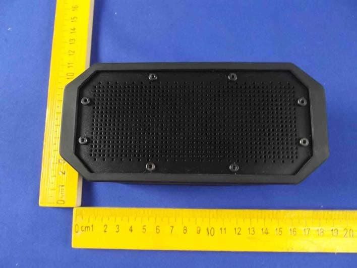
2ADTC-W1
Jan 11, 2015Waterproof Bluetooth Speaker
Equipment Class
DSS - Part 15 Spread Spectrum Transmitter