2ADUG-CPE870Wireless Access Point
Shenzhen Yunlink Technology Co., Ltd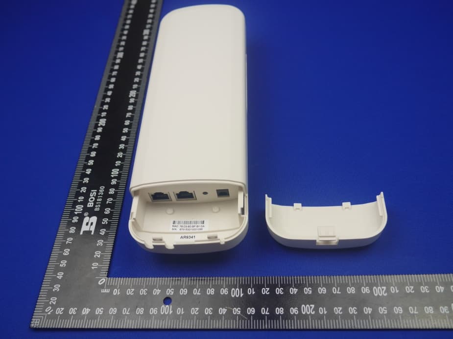
Click to zoom
Application Details
- Equipment Class
- DTS - Digital Transmission System
- Date of Grant
- Aug 27, 2015
- Application Purpose
- Original Equipment
- Date of Application
- Aug 27, 2015
- Equipment Note
- Wireless Access Point
- Frequency Range
- 2422.00000000 - 2452.00000000
- Country
- China
Documents & Files
Document Text
Text extracted from the exhibit documents filed with the FCC. Open a document above to read the original.
Users Manual
FCC INFORMATION (additional) Note: This equipment has been tested and found to comply with the limits for a Class B digital device, pursuant to part 15 of the FCC Rules. These limits are designed to provide reasonable protection against harmful interference in a residential installation. This equipment generates, uses and can radiate radio frequency energy and, if not installed and used in accordance with the instructions, may cause harmful interference to radio communications. However, there is no guarantee that interference will not occur in a particular installation. If this equipment does cause harmful interference to radio or television reception, which can be determined by turning the equipment off and on, the user is encouraged to try to correct the interference by one or more of the following measures: —Reorient or relocate the receiving antenna. —Increase the separation between the equipment and receiver. —Connect the equipment into an outlet on a circuit different from that to which the receiver is connected. —Consult the dealer or an experienced radio/TV technician for help. RF Exposure: A distance of 20 cm shall be maintained between the antenna and users, and the transmitter may not be co-located with any other transmitter or antenna.
Users Manual
Shenzhen Yunlink Technology Co., Ltd Manual of Wireless Access Point T his is the manual of outdoor CPE, which will approximate guide you how to set and apply the outdoor CPE, it provide a conve nient graphical interface for network construction and maintenance person, as well as a user through a simple and acc urate operation, and configuration management of the CPE. 1 st Connect ion and Power Supply Shenzhen Yunlink Technology Co., Ltd 1st:Po rt Connection and power supply Instruction of different port: P1 CPE Port Connection 1.Please use a power supply of 12V DC adapter or 24V POE adapter, WAN / LAN port is the PoE Port. 2.Reset: There are two ways to reset the CPE: 3.CPE Manage page: Click “Management”, then “Save/Reload Settings”, then click“Reset Settings”to finish the CPE Reset 2. Press the Reset Button on CPE more than 15 seconds, then release, the device will reboot and restore to factory settings 4.The connection way of CPE, PoE Adapter and PC: P2 Connection diagram of CPE and PoE adapter Pay Attention Pls make sure the CPE’s power supply is normal in reset process, or the CPE will be damaged and can’t reboot Shenzhen Yunlink Technology Co., Ltd 2 nd Steps:Login 1)Connect the CPE with computer as P2 picture 2 ) Configure the PC’s local connection IP address as 192.168.188.X (X is number from 2 to 254), subnet mask is 255.255.255.0, follow P3 and P4 to finish. P3 Setting of computer’s IP address Pay Attention Incorrect Connection or the use power adapter and PoE adapter not from our factory, the CPE will be damaged Shenzhen Yunlink Technology Co., Ltd P 4 Setting of computer’s IP address 3) Input 192.168.188.253 into IE browser, then pop up the login page, the default login user name: Admin, Passwords: admin, pls do following P5 P5 Log in 5. After login, then P6 will be showed: Shenzhen Yunlink Technology Co., Ltd P6: System Status 3rd : Quickly Configure Wireless AP ①Gateway Mode: Click “Gateway Mode” and choose the right WAN access type, then input the right SSID, Channel, key as like. ②WiFi Repeater and Station operation configuration A. Login the Web management page, click “ Repeater Mode”, then “Scan AP” B. Select the AP’s SSID want to bridge C. input the AP’s key, and apply changes D. In Repeater Mode, the SSID is disable in default setting, it work as Station; Then if need SSID broadcast in this operation mode, just manual to change under Advanced Settings, So, click sure in this part to finish the repeater operation mode setting. E. After this step, can click the Device status to check the status of this Wireless AP. And it will show Wireless AP’s LAN Interface, WLAN status and Sigbal Strength. F. Then if SSID should be broadcast under repeater mode, pls click “Advanced Settings” , then “2.4GHz Repeater” will pop up. If want to bridge another AP’s SSID, then can setup in this part and Apply changes. Shenzhen Yunlink Technology Co., Ltd P14 2.4GHz Repeater G. Click “2.4GHz Virtual AP”, will show SSID shut off, if need SSID broadcast, pls follow steps of 1,2,3,4,5,6 showed in following picture. This Wireless AP will work under wireless repeater and broadcast SSID after apply changes. P15 2.4GHz Virtual AP ③AP Mode Plug and Play to transmit wireless signal for wireless end users form wired networking. In this part, user can mark the AP’s location and name for easy problem checking. Then can change SSID, Key, Channel as request. Shenzhen Yunlink Technology Co., Ltd P16 AP Mode ④WISP In this operation mode, user should confirm the WAN access type at first, then set the SSID, key, Channel as request. P17 WIPS Mode ⑤Advanced Settings: 1. System Status Click “ Advance Settings”, will show system status, such as firmware version, build time, System uptime... Shenzhen Yunlink Technology Co., Ltd P 18 System Status Click 2.4GHz Wireless Status, will show Wireless AP’s WLAN Status, Channel Band, SSID... P19 2.4GHz Wireless Status If want to check LAN status, pls check following picture P20 LAN Status 2. Operation Mode: Set operation mode manually, choose the right operation mode, then apply changes. The function of this part will be same as Quick Setup step. Shenzhen Yunlink Technology Co., Ltd P21 Operation Mode 3. 2.4GHz Wireless: In this part, use can scan AP’s SSID, disable or enable AP’s SSID, modify Channel, Security.. P22 2.4GHz Wireless Shenzhen Yunlink Technology Co., Ltd 2.4GH Z Virtual AP 2.4GHz Access Control P2 3 2.4GHz Advanced Note: T he frequency selection feature is disabled by firmware for devices marketed to the US. only channels 1-11 will be used in North America. Country code selection is disabled. Shenzhen Yunlink Technology Co., Ltd 4. Net work Setting LAN Interface Setup mainly showed as follow: P24 Network Setting 5. Management In this part, user can set Time zone, show Log info, upgrade firmware, change login user name and password; P25 Management 6. Upgrade Firmware Pls click Upgrade Firmware, then browse and choose the firmware should upgrade, then click upgrade to upgrade the firmware. P 26 Firmware Upgrade After finish firmware upgrade, pls click Save/Reload Settings, then reset settings to default. (GMT+13)United States Shenzhen Yunlink Technology Co., Ltd Af ter that, the firmware upgrade is finished. 7. Share Internet and Obtain IP address automatically Set computer’s TPC/IP as Obtain an IP address automatically, Obtain DNS server address automatically as following picture showed. the computer will obtain the IP address from router or base station to get Internet. Shenzhen Yunlink Technology Co., Ltd T rouble Shooting: F 1 The Failure phenomenon and solution F ailure phenomenon Solution SYS Indicator off Pls make sure the PoE module connection is right. POE Port connect with AP, LAN port connect with computer Can’t la nd to Wireless AP through Web page Pls check the IP address of computer and Wireless AP to see whether they are in same networking segment, The method is click “start”-“Run” input“cmd”,ping 192.168.188.253 to test the Wireless AP connec…
Text truncated - open the document above for the full version.
Cover Letter(s)
Shenzhen Yunlink Technology Co.,Ltd B2 Building, An'le Industrial Zone, Hangcheng Road, gushu, xixiang town, Baoan, Shenzhen,518100, Guangdong Province, China FCC Authorization Letter Number: CF304 Version: V03 Date: 01-08-2011 We, (the approval holder) Company name Shenzhen Yunlink Technology Co.,Ltd Address B2 Building, An'le Industrial Zone, Hangcheng Road, gushu, xixiang town, Baoan, City Shenzhen, 518100, Guangdong Province, Country China declare that the following representative (agent): Name (person) KAIT CHEN Company name WST Certification & Testing (HK) Limited Address 12/F., San Toi Building,137-139 Connaught Road Central, City Hong Kong, Country China is hereby authorized to apply the following equipment for certification on our behalf: Product Description Wireless Access Point Type or Model(s) CPE-870, CPE-880, CPE-860, CPE-3200, AP80, CPE-970,CPE-980, CPE-960, AP21, AP20, AP28, XD-9341, LT-9341 Tradename or Brand(s) N/A We also authorize Teleconformity (Mr. M. Koop, Manager Certification, Address: Rietven 31, 7534NH Enschede, the Netherlands) to apply and sign this application for certification, registration or filing on our behalf (as representative agent or certifier). Attestation: City and Country:Date:Name: (this must be a person) Function:Signature: (or official company stamp) Shenzhen, ChinaAug. 21, 2015Jessy WuManager
Cover Letter(s)
FCC Sub j Dea Our The The uni n “De The If y o Your Sign Clie n Clien Cont ID: 2ADUG-CPE870 ject: Attestati r Sirs, products wi t transmitter i device is als o ntentional rad eclaration of Tes t lab: Co m ou have any q rs sincerely, atory nt ’ s si gnatu r e : nt’s name / title act information Date: 2015‐08-16 ion Letter “D th the above s authorized o defined as “ diators, where Conformity” mpliance Cert uestions, ple e : / address: D eclaration of FCC ID are d e under the “C “PC Periphery e we hereby procedure. tification Serv ease feel free DOC ATTESTAT Conformity” efined as com Certification” y” acc to §15 declare, tha t vices Inc. to contact m TION LETTER mposite devic procedure. .101 E quipm e t we apply an me at the addr e. ent authoriza d follow the ress shown b ation of below. Shenzhen Yunlink Technology Co.,Ltd Jessy Wu /Manager Shenzhen Yunlink Technology Co.,Ltd B2 Building, An'le Industrial Zone, Hangcheng Road, gushu, xixiang town, Baoan, Address:No.81-1, Lane 210, Bade Rd. 2, Luchu Hsiang, Taoyuan Hsien, (338)Taiwan, R.O.C Test Report Number:150806145-E Date of issue:2015-08-09 Shenzhen, 518100, Guangdong Province, China
RF Exposure Info
FCC RF Exposure EUT Description: Wireless Access Point Model No.: CPE-870, CPE-880, CPE-860, CPE-3200, AP80, CPE-970,CPE-980, CPE-960, AP21, AP20, AP28, XD-9341, LT-9341 FCC ID: 2ADUG-CPE870 1.L imits The criteria listed in the following table shall be used to evaluate the environment impact of human exposure to radio frequency (RF) radiation as specified in 1.1307(b) L imits for Maximum Permissible Exposure (MPE) F = frequency in MHz Formula: Pd = (P out*G)/(4*π*r 2 ) Where : Pd = power density in mW/cm 2 , Pout = output power to antenna in mW; G = gain of antenna in linear scale, π= 3.14; R = distance between observation point and center of the radiator in cm Pd id the limit of MPE, 1 mW/cm2. If we know the maximum gain of the antenna and the total power input to the antenna, through the calculation, we will know the distance r where the MPE limit is reached. 2.Test Procedure Software provided by client enabled the EUT to transmit and receive data at lowest, middle and highest channel individually. 3.T est Result of RF Exposure Evaluation Output power (dBm/W) Antenna Gain(dBi) Power Density at R=20cm (mW/cm 2 ) Limit (mW/cm 2 ) Result 802.11b 17.04/0.05058 5 0.05033 1.0 Pass 802.11g 16.48/0.04446 5 0.04424 1.0 Pass 802.11n(20MHz) 16.82/0.04808 5 0.04785 1.0 Pass 802.11n(40MHz) 14.25/0.02660 5 0.02647 1.0 Pass
Test Report
Page 1 of 69Report No.: WST15081202 FCC TEST REPORT Test report On Behalf of Shenzhen Yunlink Technology Co., Ltd For Wireless Access Point Model No.: CPE-870, CPE-880, CPE-860, CPE-3200, AP80, CPE-970,CPE-980, CPE-960, AP21, AP20, AP28, XD-9341, LT-9341 FCC ID: 2ADUG-CPE870 Prepared for : Shenzhen Yunlink Technology Co., Ltd B2 Building, An’le Industrial Zone, Hangcheng Road, gushu, xixiang town, Baoan, Shenzhen Guangdong Province China Prepared By : Shenzhen WST Testing Technology Co., Ltd. 1F, No.9 Building,TGK Science & Technology Park, Yangtian Rd., NO.72 Bao'an Dist., Shenzhen, Guangdong, China. 518101 Date of Test: August 07-18, 2015 Date of Report: August 18, 2015 Report Number: WST15081202 Page 2 of 69Report No.: WST15081202 TEST RESULT CERTIFICATION Applicant’s name ................. : Shenzhen Yunlink Technology Co., Ltd Address ................................. : B2 Building, An'le Industrial Zone, Hangcheng Road, gushu, xixiang town, Baoan, Shenzhen Guangdong Province China Manufacture's Name ............ : Shenzhen Yunlink Technology Co., Ltd Address ................................. : B2 Building, An'le Industrial Zone, Hangcheng Road, gushu, xixiang town, Baoan, Shenzhen Guangdong Province China Product description Trade Mark: N/A Product name............................ : Wireless Access Point Model and/or type reference : CPE-870, CPE-880, CPE-860, AP80, CPE-970,CPE-980, CPE-960, CPE-3200, AP21, AP20, AP28, XD-9341,LT-9341 Standards ............................. : FCC Rules and Regulations Part 15 Subpart C Section 15.247 ANSI C63.4: 2009 This publication may be reproduced in whole or in part for non-commercial purposes as long as the WST Certification & Testing (HK) Limited is acknowledged as copyright owner and source of the material. WST Certification & Testing (HK) Limited takes no responsibility for and will not assume liability for damages resulting from the reader's interpretation of the reproduced material due to its placement and context. Date of Test ........................................... : Date (s) of performance of tests ............. : August 07-18, 2015 Date of Issue .......................................... : August 18, 2015 Test Result.............................................. : Pass Testing Engineer : (Eric Xie) Technical Manager : (Dora Qin) Authorized Signatory : (Kait Chen) Page 3 of 69Report No.: WST15081202 Table of Contents Page 1 . TEST SUMMARY 5 1.1 TEST FACILITY 6 1.2 MEASUREMENT UNCERTAINTY 6 2 . GENERAL INFORMATION 7 2.1 GENERAL DESCRIPTION OF EUT 7 2.2 Carrier Frequency of Channels 8 Operation of EUT during testing 8 2.3 DESCRIPTION OF TEST SETUP 9 OPERATION OF EUT DURING TESTING 9 2.4 MEASUREMENT INSTRUMENTS LIST 10 3 . 6DB BANDWIDTH MEASUREMENT 12 3.1 Block Diagram of Test Setup 12 4 Maximum Peak Output Power 20 4.2 Limits 20 4.3 Test Procedure 20 4.4 Test Result 21 5 Power Spectral Density Measurement 27 5.2 Limits 27 5.4 Test Result 28 6 Band Edge Compliance Test 35 6.2 Limits 35 6.3 Test Procedure 35 6.4 Test Result 36 7 Radiated Spurious Emission Test 43 7.2 Limits 44 7.3 Restricted bands of operation 44 7.3 Test Procedure 45 7.4 Test Result 46 8 Conducted Spurious Emission Compliance Test 52 8.2 Limits 52 8.3 Test Procedure 52 8.4 Test Result 52 9 AC Power Line Conducted Emission For Part 15 Section 15.207(A) 65 Page 4 of 69Report No.: WST15081202 Table of Contents Page 9.2 Limits 65 9.3 Test Procedure 65 9.4 Test Result 65 10 Antenna Requirement 67 11 Photograph of Test 68 Page 5 of 69Report No.: WST15081202 1. TEST SUMMARY FCC Rules Description of Test Result Section 15.247(a)2) 6dB Bandwidth Test Compliant Section 15.247(e) Power Spectral Density Test Compliant Section 15.247(b)(3) Maximum Peak Output Power Test Compliant Section 15.247(d) Band Edge Compliance Tes Compliant Section 15.247(d) Section 15.209) Radiated Spurious Emission Test Compliant Section 15.247(d) Conducted Spurious Emission Test Compliant Section 15.207 AC Power Line Conducted Emission Test Compliant Section 15.203 Antenna Requirement Compliant Page 6 of 69Report No.: WST15081202 1.1 TEST FACILITY Test Firm : Shenzhen WST Testing Technology Co., Ltd. Certificated by FCC, Registration No.: 939433 Address : 1F, No.9 Building,TGK Science & Technology Park, Yangtian Rd., NO.72 Bao'an Dist., Shenzhen, Guangdong, China. 518101 Tel : (86)755-33916437 Fax : (86)755-27822175 1.2 MEASUREMENT UNCERTAINTY Measurement Uncertainty Conducted Emission Expanded Uncertainty = 2.23dB, k=2 Radiated emission expanded uncertainty(9kHz-30MHz) = 3.08dB, k=2 Radiated emission expanded uncertainty(30MHz-1000MHz) = 4.42dB, k=2 Radiated emission expanded uncertainty(Above 1GHz) = 4.06dB, k=2 Page 7 of 69Report No.: WST15081202 2.GENERAL INFORMATION 2.1 GENERAL DESCRIPTION OF EUT Equipment Wireless Access Point Model Name CPE-870 Serial No CPE-880, CPE-860, CPE-3200, AP80,CPE-970,CPE-980, CPE-960, AP21, AP20, AP28, XD-9341, LT-9341 FCC ID 2ADUG-CPE870 Model Difference All the model are the same circuit and RF module,except the appearance colour, this report only test mode name: CPE-870. Modulation Type OFDM(64-QAM, 16-QAM, QPSK,BPSK) Antenna Type Internal WLAN Operation frequency 802.11b: 2412-2462MHz 802.11g: 2412-2462MHz 802.11n HT20: 2412-2462MHz 802.11n HT40: 2462-2452MHz Number of Channels 802.11b/g/n (20MHz):11 802.11n (40MHz): 7 Data Rate 802.11b: 11, 5.5, 2, 1 Mbps 802.11g: 54, 48, 36, 24, 18, 12, 9, 6 Mbps 802.11n: up to 300Mbps Modulation Type CCK, OFDM Power Source AC Voltage Power Rating Input 100-240V, 50/60Hz,0.8A Output DC 12V,1A Adapter Model GRT-240100 Page 8 of 69Report No.: WST15081202 2.2 Carrier Frequency of Channels Operation of EUT during testing Operating Mode The mode is used: 802.11b Transmitting mode Low Channel: 2412MHz Middle Channel: 2437MHz High Channel: 2462MHz 802.11g Transmitting mode Low Channel: 2412MHz Middle Channel: 2437MHz High Channel: 2462MHz 802.11n (HT20) Transmitting mode Low Channel: 2412MHz Middle Channel: 2437MHz High Channel: 2462MH…
Text truncated - open the document above for the full version.
Test Setup Photos
12 Photograph of Test 12.1 Radiated Emission 12.2 AC Power Line Conducted Emission
Contact Information
Applicant
Jessy Wu(Manager)
Technical Contact
Test Firm
Shenzhen WST Testing Technology Co., Ltd.Long Zhou
Technical Specifications
| # | Rule Parts | Frequency Range | Power Output |
|---|---|---|---|
| 2 | 15C | 2.42 GHz - 2.45 GHz | 26.61 mW |
Other Applications from Shenzhen Yunlink Technology Co., Ltd
2ADUG-HWAP-AX880
Jul 10, 2023Access Point
Equipment Class
DTS - Digital Transmission System