2ADUNICEMAN50BLEBattery Charger
PREMIER MERCHANDISES LIMITED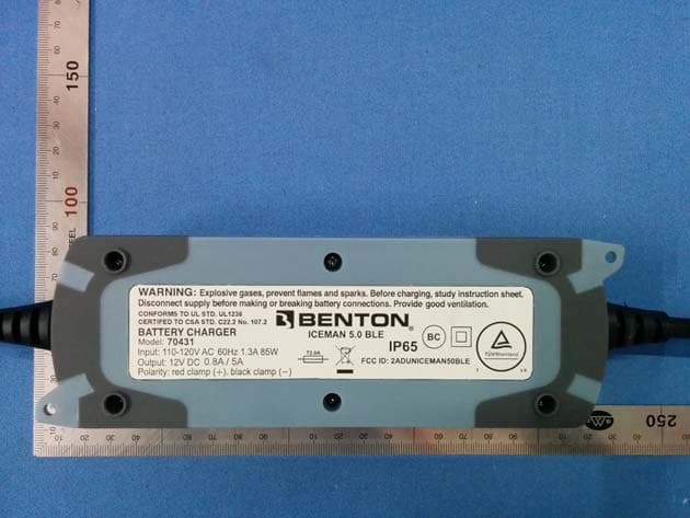
Click to zoom
Application Details
- Equipment Class
- DXX - Part 15 Low Power Communication Device Transmitter
- Date of Grant
- May 21, 2015
- Application Purpose
- Original Equipment
- Date of Application
- May 20, 2015
- Equipment Note
- Battery Charger
- Frequency Range
- 2402.00000000 - 2480.00000000
- Company
- PREMIER MERCHANDISES LIMITED
- Country
- Hong Kong
Documents & Files
Document Text
Text extracted from the exhibit documents filed with the FCC. Open a document above to read the original.
Users Manual
User‘s Manual 8 STEP 12V 5A BENTON ICEMAN 5.0 BLE SWITCH MODE BATTERY CHARGER For Lead acid batteries 1.2-120Ah (charging), up to 160 Ah for maintenance User’s manual and guide to professional battery charging For Your Safety This manual contains important safety and operating instructions. Read this manual carefully before using the charger for the first time and keep the manual in a safe place for future reference. Mode Button Power LED Error LED Ready To Use Fully Charged Normal Battery Mode Small Battery Mode Cold Mode Boost Mode Cold Mode Boost Mode Contents 1) BENTON® ICEMAN 5.0 BLECharger 2) Quick contact battery leads with clamps 3) Quick contact battery leads with eyelet terminals (Ø 6.3mm) with in-line battery protection fuse (10A) for permanent attachment to the battery posts to allow quick connection/disconnection through snap-connector. 4) User Manual AC Plug Mains Cable H05RN-F Rubber Charge Cable HPN Rubber Cable HPN Rubber Cable Eyelet M6 Terminals Clamp HPN Rubber Cable DC Connector 10A Fuse Holder Safety Information BENTON® ICEMAN 5.0 BLE charger is designed for charging 12V 1.2-160Ah Lead-Acid rechargeable batteries. Do not intend to supply power to low voltage electrical system. Do not use it for any other purpose. WARNING! DO NOT ATTEMPT TO CHARGE A NON-RECHARGEABLE BATTERY (PRIMARY CELLS). Do not use the charger with a damaged cable. It must be replaced by the manufacturer, its service agent or similarly qualified technician in order to ensure safety. Normally, a battery is grounded either, on negative or positive terminal to the vehicle’s chassis. The charger’s DC Clips are to be connected to the battery terminal not connected to the chassis first. The other connection is to be made to the terminal connected to the chassis, far from the battery and fuel line. The battery charger is then to be connected to the power supply. After charging, disconnect the battery charger from supply mains. Remove the chassis connection and the battery connection, respectively. This will reduce back drain current. During charging the battery must be placed in a well ventilated area. This appliance can be used by children aged from 8 years and above and persons with reduced physical, sensory or mental capabilities or lack of experience and knowledge if they have given supervision or instruction concerning use of the appliance in a safe way and understand the hazards involved. Children shall not play with appliance. Cleaning and user maintenance shall not be made by children without supervision. Charging Modes Mode 14.4V/0.8A This mode is normally suitable for batteries less than 14 Ah Mode 14.7V/0.8A This mode is recommended for AGM batteries less than 14 Ah. This mode is also suitable for charging batteries in sub-zero temperatures. BOOST Mode 14.4V/0.8A + 16.0V/0.3A, This mode is suitable to recover severely discharged batteries smaller than 14 Ah. Recommended to boost at least once a year. BOOST Mode 14.7V/0.8A + 16.0V/0.3A This mode is suitable to recover severely discharged AGM batteries smaller than 14 Ah or charging in sub-zero temperatures. Mode 14.4V/5.0A This mode is normally used for WET, MF, VRLA, AGM, GEL and Calcium batteries Mode 14.7V/5.0A This mode is recommended for AGM batteries. This mode is also suitable for charging batteries in sub-zero temperatures. BOOST Mode 14.4V/5.0A + 16.0V/1.5A This mode is suitable to recover severely discharged batteries. Recommended to boost atleast once a year. BOOST Mode 14.7V/5.0A + 16.0V/1.5A This mode is suitable to recover severely discharged AGM batteries or charging in sub- zero temperatures. OPERATION Charging 1) Charging of a permanently installed battery in a vehicle a) Before connecting or disconnecting the battery leads, the power cord should be removed from the mains. b) Check polarity of battery post. A positive (“+”) battery post usually has a larger diameter than a negative (“-”) post. c) Identify the pole of battery which is connected to the chassis (earth). Normally the negative terminal is connected to the chassis. d) Charging of negative earthed battery: • Make sure the black clamp or eyelet terminal (“-” pole connection) has not contact with the fuel line or the battery. • Connect the red clamp or eyelet terminal (“+”) to the positive (“+”) pole of the battery and the black clamp or eyelet terminal (“-“) to the vehicle chassis. e) Charging of positive earthed battery: • Make sure the red clamp or terminal (“+” pole connection) has no contact with the fuel line or the battery. • Connect the black clamp or eyelet terminal (“-”) to the negative (“-”) pole of the battery and the red clamp or eyelet terminal (“+“) to the vehicle chassis. 2) Charging of a battery not connected to a vehicle a) Before connecting or disconnecting the battery leads, the power cord should be removed from the mains. b) Connect the red clamp or eyelet terminal (“+”) to the positive (“+”) pole of the battery and the black clamp or eyelet terminal (“-“) to the negative (“-“) pole. 3) Connect charger to the mains. 4) Select charging mode For Small batteries less than 12Ah Press MODE button for 3 second to change charge from small batteries to normal batteries For normal batteries larger than 12Ah By pressing MODE button several times combination of Cold charge and BOOST charge options could be selected. 5) At step 4 battery is ready to use and step 7 it is fully charged. Bulk Charging Time Battery size Mode For About 80% Charge (Ah) (hours) 6 7 8 9 12 14 20 4 60 12 80 16 120 24 Batteries below 12 Ah should not be charged with 5A current Technical Data MODEL ICEMAN 5.0 BLE Input Voltage AC 220-240VAC, 50/60Hz Output Voltage Nominal: 12V Input Current 0.65A RMS max Minimum Battery Voltage 2.0V Output Power 60W Efficiency 80% Charging Voltage 14.4V, 14.7V, BOOST 16V Charging Current 5A max Back Current Drain* 5 mA Ripple Voltage < 2% Ambient Temperature -30°C to 50°C, Reduced output power at higher temperature Type of Charger Eight step, …
Text truncated - open the document above for the full version.
ID Label/Location Info
Label location
Test Report
Global United Technology Services Co., Ltd. Report No.: GTSE14120223701 Authorized Signature: Robinson Lo Laboratory Manager This report details the results of the testing carried out on one sample. The results contained in this test report do not relate to other samples of the same product and does not permit the use of the GTS product certification mark. The manufacturer should ensure that all products in series production are in conformity with the product sample detailed in this report. This report may only be reproduced and distributed in full. If the product in this report is used in any configuration other than that detailed in the report, the manufacturer must ensure the new system complies with all relevant standards. Any mention of GTS or testing done by GTS in connection with, distribution or use of the product described in this report must be approved by GTS in writing. This document cannot be reproduced except in full, without prior written approval of the Company. Any unauthorized alteration, forgery or falsification of the content or appearance of this document is unlawful and offenders may be prosecuted to the fullest extent of the law. Unless otherwise stated the results shown in this test report refer only to the sample(s) tested and such sample(s) are retained for 90 days only. FCC REPORT Applicant: PREMIER MERCHANDISES LIMITED Address of Applicant: UNIT 2305-15, 23/F METRO LOFT, 38 KWAI HEI STREET, KWAI CHUNG, NT, HONG KONG Equipment Under Test (EUT) Product Name: Battery Charger Model No.: ICEMAN 5.0, 70340, 70361, 70410, 70424 ICEMAN 5.0 BLE, 70396, 70397, 70431, 70432 Trade Mark: BENTON FCC ID: 2ADUNICEMAN50BLE Applicable standards: FCC CFR Title 47 Part 15 Subpart C Section 15.249 Date of sample receipt: April 13, 2015 Date of Test: April 13-20, 2015 Date of report issued: April 20, 2015 Test Result : PASS * * In the configuration tested, the EUT complied with the standards specified above. Report No.: GTSE14120223701 Global United Technology Services Co., Ltd. Project No.: GTSE141202237RF Room 301-309, 3th Floor, Block A, Huafeng Jinyuan Business Building, No. 300 Laodong Industrial Zone, Xixiang Road, Baoan District, Shenzhen, China Telephone: +86 (0) 755 2779 8480 Fax: +86 (0) 755 2779 8960 Page 2 of 30 2 Version Version No. Date Description 00 April 20, 2015 Original Prepared By: Date: April 20, 2015 Project Engineer Check By: Date: April 20, 2015 Reviewer Report No.: GTSE14120223701 Global United Technology Services Co., Ltd. Project No.: GTSE141202237RF Room 301-309, 3th Floor, Block A, Huafeng Jinyuan Business Building, No. 300 Laodong Industrial Zone, Xixiang Road, Baoan District, Shenzhen, China Telephone: +86 (0) 755 2779 8480 Fax: +86 (0) 755 2779 8960 Page 3 of 30 3 Contents Page 1 COVER PAGE ............................................................................................................................................ 1 2 VERSION .................................................................................................................................................. 2 3 CONTENTS .............................................................................................................................................. 3 4 TEST SUMMARY ..................................................................................................................................... 4 5 GENERAL INFORMATION ...................................................................................................................... 5 5.1 CLIENT INFORMATION ......................................................................................................................... 5 5.2 GENERAL DESCRIPTION OF EUT ......................................................................................................... 5 5.3 TEST MODE ........................................................................................................................................ 7 5.4 DESCRIPTION OF SUPPORT UNITS ....................................................................................................... 7 5.5 TEST FACILITY .................................................................................................................................... 7 5.6 TEST LOCATION ................................................................................................................................. 7 5.7 OTHER INFORMATION REQUESTED BY THE CUSTOMER ......................................................................... 7 6 TEST INSTRUMENTS LIST ..................................................................................................................... 8 7 TEST RESULTS AND MEASUREMENT DATA ...................................................................................... 9 7.1 ANTENNA REQUIREMENT ..................................................................................................................... 9 7.2 CONDUCTED EMISSIONS ................................................................................................................... 10 7.3 RADIATED EMISSION METHOD ........................................................................................................... 13 7.3.1 Field Strength of The Fundamental Signal ................................................................................ 15 7.3.2 Spurious emissions .................................................................................................................... 16 7.3.3 Bandedge emissions.................................................................................................................. 20 7.4 20DB OCCUPY BANDWIDTH .............................................................................................................. 21 8 TEST SETUP PHOTO ............................................................................................................................ 23 9 EUT CONSTRUCTIONAL DETAILS ...................................…
Text truncated - open the document above for the full version.
Test Report
FCC ID: 2ADUNICEMAN50BLE According to 447498 D01 General RF Exposure Guidance v05 The 1-g and 10-g SAR test exclusion thresholds for 100 MHz to 6 GHz at test separation distances ≤ 50 mm are determined by: [(max. power of channel, including tune-up tolerance, mW)/(min. test separation distance, mm)] ·[√f(GHz)] ≤ 3.0 for 1-g SAR and ≤ 7.5 for 10-g extremity SAR, where --f(GHz) is the RF channel transmit frequency in GHz --Power and distance are rounded to the nearest mW and mm before calculation --The result is rounded to one decimal place for comparison eirp = pt x gt = (EXd) 2 /30 where: pt = transmitter output power in watts, gt = numeric gain of the transmitting antenna (unitless), E = electric field strength in V/m, --- 10 ((dBuV/m)/20) /10 6 d = measurement distance in meters (m) ---3m So pt = (EXd) 2 /30 x gt Field strength = 94.69dBuV/m @3m Ant gain =0dBi, so Ant numeric gain= 1 So pt={ [10 (94.69) /10 6 x 3] 2 /30x1 }x1000 mW = 0.883mW So (0.883 mW /5mm)x √2.402 = 0.274<3 Then SAR evaluation is not required
Test Setup Photos
Radiated Emission Conducted Emission
Contact Information
Applicant
SUI MAN WOO(Project Engineer)
Technical Contact
Global United Technology Services Co., Ltd.Hank Yan
2nd Floor, Block No.2, Laodong Industrial Zone · Shenzhen · China
Non-Technical Contact
Global United Technology Services Co., Ltd.Hank Yan
Test Firm
Global United Technology Service Co., LtdRobinson Lo
Technical Specifications
| # | Rule Parts | Frequency Range | Power Output |
|---|---|---|---|
| 1 | 15C | 2.40 GHz - 2.48 GHz | - |