2ADUSV12Electric Unicycle
INMOTION TECHNOLOGIES CO., LTD.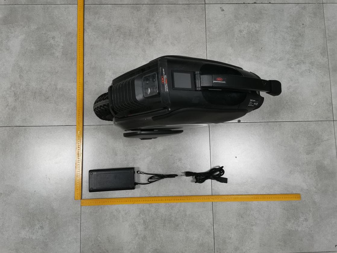
Click to zoom
Application Details
- Equipment Class
- DTS - Digital Transmission System
- Date of Grant
- Mar 13, 2021
- Application Purpose
- Original Equipment
- Date of Application
- Mar 13, 2021
- Equipment Note
- Electric Unicycle
- Frequency Range
- 2402.00000000 - 2480.00000000
- Country
- China
Documents & Files
Document Text
Text extracted from the exhibit documents filed with the FCC. Open a document above to read the original.
Users Manual
Inmotion Technologies Co., Ltd. www.inmotionworld.com Please read the user manual carefully. Don’t ride this product before you fully understand the performance. And please keep the user manual. Electric UnicycleUser Manual Model NO.:V12 Contents About this manual Product Overview Serial Number Packing list Components Features and Functions Dimension Specifification How to use Preparation before ride Install the App How to ride Care and maintenance Storage Battery maintenance Inflate and replace the inner/outer tires Cleaning and reminding Safety instructions Declaration of Hazardous Materials FCC Statement Legal Notices Personal Information Statement Intellectual Property Statement Warranty 1. 2. 2.1. 2.2. 2.3. 2.4. 2.5. 2.6. 3. 3.1. 3.2. 3.3. 4. 4.1. 4.2. 4.3. 4.4. 4.5. 4.6. 4.7. 5. 5.1. 5.2. 1 1 1 1 2 2 4 5 6 6 6 7 8 8 8 8 8 9 10 11 11 11 12 12 1. About this manual This manual will be applied to INMOTION V12 Electric Unicycle from INMOTION Technologies Co.,Ltd. Fully understand all the warnings and precautions listed in this manual. To obtain the latest info about the features/functions and safety guidence, please download the user manual in digital version from the official website. www.inmotionworld.com.Before you ride the electric unicycle, be sured that you have watched the tutorial video online if you are a beginner. Standard of Product executivity:Q/LXTX 002-2017 2. Product Overview V12 is an electric unicycle designed for urban commute, with 16 inch wheels, powerful motor, intelligent BMS, touch-screen, Automatic Headlight, high-quality speaker and other remarkable features and functions, for higher top-speed and more mileage (hereinafter referred to as V12 unicycle). Based on the principle of dynamic balance, the change of the unicycle's posture could be detected by the built-in gyroscope and acceleration sensor. Meanwhile with the servo control system, driver is able to make the below driving operations by leaning forward or backward, such as moving forward, acceleration, deceleration, braking and others. 2.1 Serial Number The Serial number (hereinafter referred to as S/N) is the unique ID to each unit of the product, which could be used for the quality tracking, repair, insurance compensation, loss confirmation, etc. And the S/N is a 16-character number could be obtained from the following locations, such as package, the body of unicycle. 2.2 Packing list Please double check all the components inside the package,and consult with your point of purchase if any parts lost 1 User Manual User Manual Accessories Charger Warnings: Do not dis-assemble or modify the unicycle without permission from manufacturer, otherwise it may cause irreversible damage to the body of unicycle Power on/off: Long press the button to power on/off. User is allowed to set the access code for Touch Screen via Inmotion App. Head-light: Under the status of power on, one more click the button to light on/off. The head-light could be light off on Touch Screen or INMOTION App. Tail-light: Always on while riding, and blink when braking. Anti-spinning button: At the static status, the motor stops running when hold the Anti-spinning button. Voice Prompt: V12 provide the High-quality voice prompt while operating the vehicle or the vehicle works abnormally. On Inmotion App, user is allowed to customize the voice prompt, change the , Volume up/down, Switch on/off. If the voice prompt lost or with noise, please re-download via Inmotion App. • • • • • 2.3 Components 2.4.Features and Functions 2 Charging: The original charger is DC 100.8V/2.3A. The indicator of the charger is red/green, mean on-charging/charging completed. With two chargers working together, the charging time will be 50% cut off. The USB port could be used for power output. • Touch-Screen: Check real-time info of Vehicle on riding, set the parameters quickly. • Automatic Headlight: Automatically adjust the lighting of head-light according to ambient light and speed Audio System: 4 set of high-quality speaker were assembly in the front/rear body of V12, and they could be connected with smart phone via bluetooth. Decorative light: 6 set of decorative LED strip were assembly on the left/right body of V12. Factory default lighting effect was provided, and user could DIY it as well. • • • ••Trolley Handle: Press the unlock button under the Trolley handle to unfold it; when the Trolley handle is not in use, hold the lock button under the Trolley handle to fold. Kickstand: Turn down the kickstand to park the unicycle. 3 4 2.5 Dimension 5 2.6. Specification Specification Dimension Payload & Weight Requirement of rider Performance Battery Motor Charger Display Parameter 497*190*607mm 120kg Over 16 years old 160KM 88.8V- 2500W 100~240VAC/50~60Hz Approx. 100.8V - Approx. 2.3A CE,FCC,ETL Approx. 9h 5000W 1750Wh (875Whx2) Capacity Equalization/overcharge/ under-voltage overheat protection -10°C~+45°CV -20°C~+45°C IPX5 IPX7 120~200cm Approx. 29kg Dimension of Vehile Touch Screen Input Voltage Output Voltage Output Current Certificate Charging Time Rating Voltage(VDC) Max.Power Rating Voltage(VDC) Rating Power Capacity Rating Power Classic Mileage Working Temp. 35° 70KM/H Max.Slope Top Speed Storage Temp. IP Rating(Body) IP Rating( Battery) Age Height Max.Payload Net Weight Typical Mileage: fully charged, 75kg payload, 25°C, no wind, and crusing at the flat road in 20km/h. Max Slope Climbing Angle: fully charged, 75kg rider get the data through a large amount of tests. Top Speed:fully charged, 25°C, no wind, and flat road. 6 3. How to use? 3.1 Preparation before using The V12 is a personal electric transportation product. It may cause unpredictable injury and property damage if without knowing the operating guidance before riding.Below we will introduce how to ride V12 correctly and various precautions. Please read carefully and follow the guidance. Before riding, please double check and make sure all parts of V12 are not damaged and installed in place. Before ridin…
Text truncated - open the document above for the full version.
External Photos
FCCID:2ADUSV12
Internal Photos
FCCID:2ADUSV12 ANT
Operational Description
version01 INMOTIONTECHNOLOGIESCO.,LTD. DeclarationconcerningAntennaSpecification Itisherebydeclaredthattheproduct ModelNo.:V12,V12S,V12F,V12D,V12E,V12C FCCID:2ADUSV12 fulfillstherequirementinFCCtestrelatingtotheantennatype. ThedevicespecifiedaboveconfirmstotheFCCrecommendationsforInternalantennatype(s) describedbelow: Bluetooth: ModelNo.ofantenna:N/A Typeofantenna:PIFAantenna Gainoftheantenna:0dBi Frequencyrange:2402MHz~2480MHz Themountingoftheantennaisfixedtotheradiomoduleandnootherantennashouldbeused. Companyname:INMOTIONTECHNOLOGIESCO.,LTD. Address:18F,B1,NanshaniPark,No.1001XueyuanAve.NanshanDistrictShenzhenChina City:Shenzhen ZIP/Postalcode:518055 Country:China Place:China Date:2021-03-12 Signature:
RF Exposure Info
RF EXPOSURE EVALUATION FCC ID: 2ADUSV12 According to FCC 1.1310: The criteria listed in the following table shall be used to evaluate the environment impact of human exposure to radio frequency(RF) Radiation as specified in §1.1307(b): Routine SAR evaluation refers to that specifically required by §2.1093, using measurements or computer simulation. When routine SAR evaluation is not required, portable transmitters with output power greater than the applicable low threshold require SAR evaluation to qualify for TCB approval. Test Results:PASS. Channel (MHz) Max output power (dBm) Tune up tolerance (dBm) Max Tune Up Power (dBm) Distance( mm) Calculation results Limit 2402-3.238 ±1 -2.23850.1853 2440-2.225±1-1.22550.2363 2480-2.970±1-1.9750.2003
Test Report
ReportNo.:18220WC10009601FCCID:2ADUSV12Page1of40 Code:AB-RF-05-a FCCTESTREPORT ClientName:INMOTIONTECHNOLOGIESCO.,LTD. Address: 18F,B1,NanshaniPark,No.1001XueyuanAve. NanshanDistrictShenzhenChina ProductName:ElectricUnicycle Date:Mar.12,2021 ShenzhenAnbotekComplianceLaboratoryLimited ReportNo.:18220WC10009601FCCID:2ADUSV12Page2of40 Code:AB-RF-05-a Contents 1.GeneralInformation ............................................................................................................................................... 5 1.1.ClientInformation ....................................................................................................................................... 5 1.2.DescriptionofDevice(EUT) ..................................................................................................................... 5 1.3.AuxiliaryEquipmentUsedDuringTest ................................................................................................... 5 1.4.DescriptionofTestModes ........................................................................................................................ 6 1.5.Listofchannels ........................................................................................................................................... 6 1.6.DescriptionOfTestSetup ......................................................................................................................... 7 1.7.TestEquipmentList .................................................................................................................................... 8 1.8.MeasurementUncertainty ......................................................................................................................... 9 1.9.DescriptionofTestFacility ........................................................................................................................ 9 2.SummaryofTestResults ................................................................................................................................... 10 3.ConductedEmissionTest ................................................................................................................................... 11 3.1.TestStandardandLimit .......................................................................................................................... 11 3.2.TestSetup .................................................................................................................................................. 11 3.3.TestProcedure .......................................................................................................................................... 11 3.4.TestData .................................................................................................................................................... 11 4.RadiationSpuriousEmissionandBandEdge ................................................................................................ 16 4.1.TestStandardandLimit .......................................................................................................................... 16 4.2.TestSetup .................................................................................................................................................. 16 4.3.TestProcedure .......................................................................................................................................... 17 4.4.TestData .................................................................................................................................................... 18 5.MaximumPeakOutputPowerTest .................................................................................................................. 26 5.1.TestStandardandLimit .......................................................................................................................... 26 5.2.TestSetup .................................................................................................................................................. 26 5.3.TestProcedure .......................................................................................................................................... 26 5.4.TestData .................................................................................................................................................... 26 6.6DBOccupyBandwidthTest ............................................................................................................................. 29 6.1.TestStandardandLimit .......................................................................................................................... 29 6.2.TestSetup .................................................................................................................................................. 29 6.3.TestProcedure .......................................................................................................................................... 29 6.4.TestData .................................................................................................................................................... 29 7.PowerSpectralDensityTest .............................................................................................................................. 32 7.1.TestStandardandLimit .......................................................................................................................... 32 7.2.TestSetup .................................................................................................................................................. 32 7.3.TestProcedure .......................................................................................................................................... 32 7.4.TestData .............................................................................................................................................…
Text truncated - open the document above for the full version.
Test Setup Photos
FCCID:2ADUSV12 PhotoofConductedEmissionMeasurement PhotoofRadiationEmissionTest
Contact Information
Applicant
Fengling Qiu
Test Firm
Shenzhen Anbotek Compliance Laboratory LimitedJeff Zhu
Technical Specifications
| # | Rule Parts | Frequency Range | Power Output |
|---|---|---|---|
| 1 | 15C | 2.40 GHz - 2.48 GHz | 600.00 µW |
Other Applications from INMOTION TECHNOLOGIES CO., LTD.
2ADUSV8S
May 19, 2024Electric Unicycle
Equipment Class
DTS - Digital Transmission System
2ADUSV12PRO
Mar 26, 2024Electric Unicycle
Equipment Class
DTS - Digital Transmission System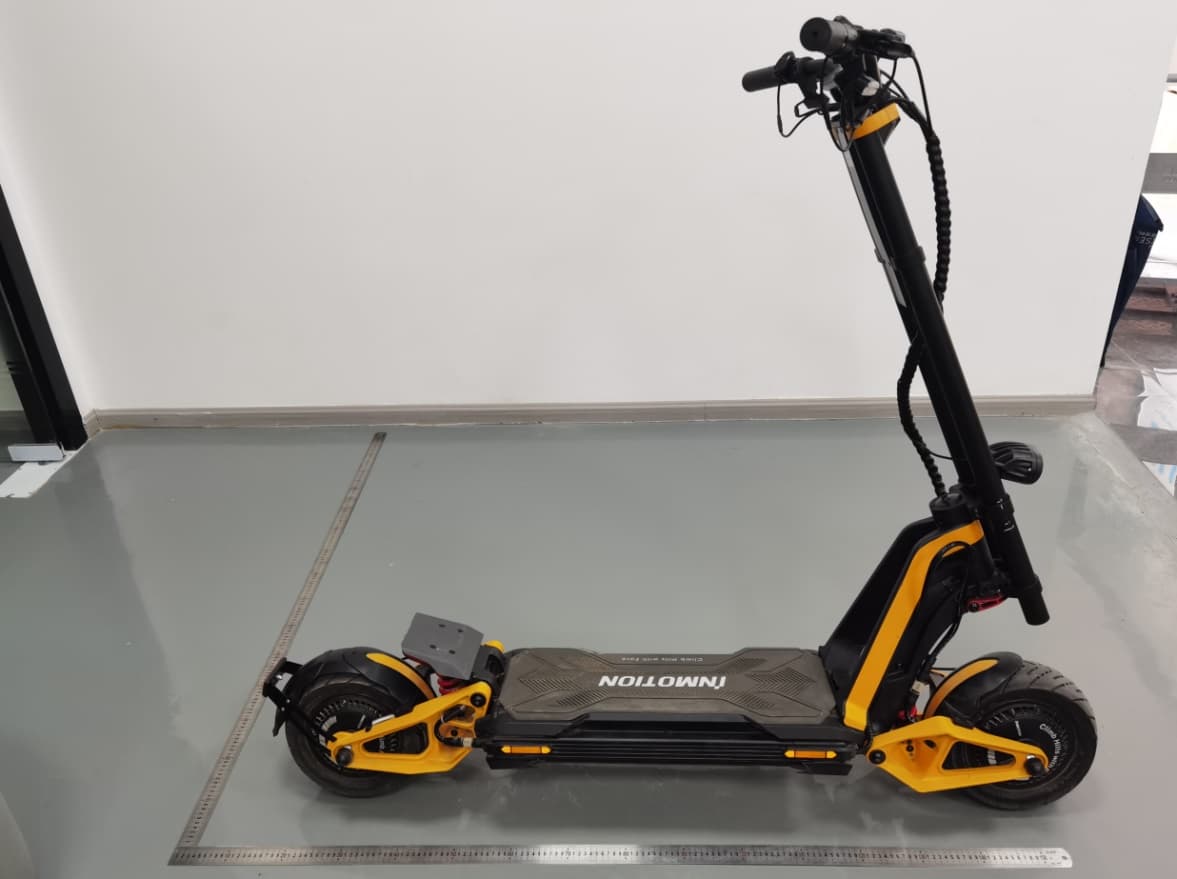
2ADUSRS
Jul 12, 2023Electric Scooter
Equipment Class
DTS - Digital Transmission System
2ADUSV13
Dec 11, 2022Electric Unicycle
Equipment Class
DTS - Digital Transmission System
2ADUSLE1
Nov 22, 2022Electric scooter
Equipment Class
DTS - Digital Transmission System