2ADUW-007-1002The Intellirod Spine LoadPro System is a disposable intraoperative biomedical telemetry system that measures the strain on a 5.5mm titanium rod used during corrective spinal surgeries.
Intellirod Spine, Inc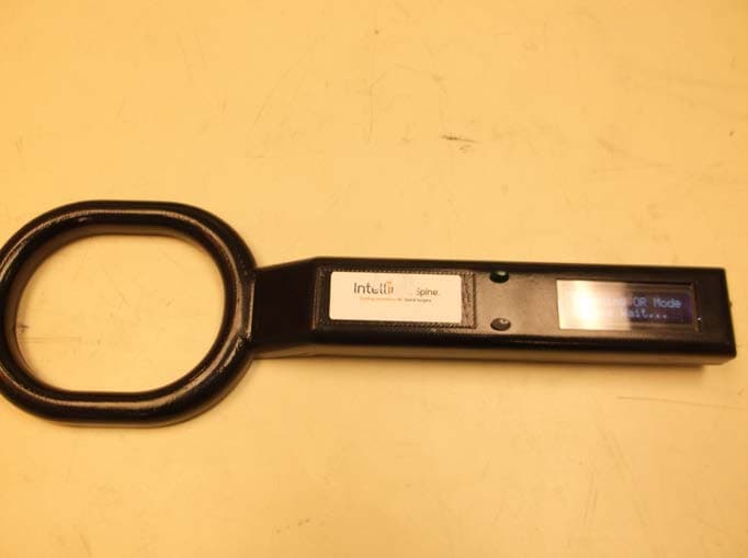
Click to zoom
Application Details
- Equipment Class
- DXX - Part 15 Low Power Communication Device Transmitter
- Date of Grant
- Jan 28, 2015
- Application Purpose
- Original Equipment
- Date of Application
- Jan 26, 2015
- Equipment Note
- The Intellirod Spine LoadPro System is a disposable intraoperative biomedical telemetry system that measures the strain on a 5.5mm titanium rod used during corrective spinal surgeries.
- Frequency Range
- 13.56000000 - 13.56000000
- Company
- Intellirod Spine, Inc
- Country
- United States
Documents & Files
Document Text
Text extracted from the exhibit documents filed with the FCC. Open a document above to read the original.
Users Manual
QAM 0002 [DRAFT] - Intellirod Disposable System Reader Instructions for Use QAM 0002 Draft – Revision 1.1 12/18/2014 Intellirod Spine Disposable System Reader Instructions for Use Intended Use: The Intellirod Spine LoadPro system is intended to be used as an aid in the assessment of instrumented posterolateral or interbody thoracolumbar rod strains whenever the surgeon is concerned about the amount of strain imparted on the rod or the asymmetry of strain on bilateral rods. The Sensor is intended for application in the thoracolumbar spine from T1 to S1. The System is intended to be used by Surgeons, Nurses, Physicians Assistants, and Residents during the surgical procedure. The LoadPro Reader is intended to be use with the LoadPro Sensor (Model: 007-1001) only. User Interface Description: Scan Button – Green button – initiates continuous reading Clear Button – Gray button (has dimple on top of button) – stops scanning Display – 2 line text display – displays strain values for all sensors within reading field. If more than 2 sensors detected, the display will scroll every second. On/Off switch – slide switch on end of handle Battery Door – on back side of handle – requires T8 Torx drive to open Battery – CR123 lithium battery – provides approximately 1 hour of continuous scanning. Description of Operation Once the Scan button is pressed, the Reader continuously scans and displays data from all sensors within the field with a maximum of 2 sensors. The Reader will beep for every valid Sensor data seen. Pressing the Clear button at any time will clear the display and turn off the RFID Field. To begin scanning again, the Scan button will need to be pressed. NOTE: if the display becomes dim or the Reader stops beeping (seeing sensor data) replace the battery (see Maintenance section for instructions on replacing the battery). Max Load of the Sensor is +/- 3000 microstrain Sensor data is displayed on the Reader as: 8-digit serial number +/-4-digit strain value. Sensor data is displayed in whole numbers of microstrain. Sensor data range is +/-2000 microstrain +/- 10% Items required for Proper Use Sterile sheath large enough to hold the Reader Fresh/new CR123 battery Operating Instructions: 1. Prior to use, inspect the Reader’s plastic enclosure for damage and make sure the batter door is fully inserted and screwed down. 2. Always insert a new battery before each use (see Maintenance section for instructions on replacing the battery) 3. Pass the Reader into sterile field by placing the Reader into a sterile sheath and close the end of the sheath. 4. Keeping the Reader inside the sterile sheath, slide the power switch to ON. QAM 0002 [DRAFT] - Intellirod Disposable System Reader Instructions for Use QAM 0002 Draft – Revision 1.1 12/18/2014 5. When ready, press the Scan (Green) button. The RFID field will turn on and start scanning for Sensors. 6. Hold the Reader, in the sterile sheath, over the Sensor(s) within 3” of the top of the sensors. The Reader will beep for every Sensor read. The display will update with every reading. 1 Sensor per line. 7. If scanning needs to stop, press the Clear (Gray) button. The RFID field will be turned off and the display cleared. 8. To restart scanning, press the Scan (Green) button. 9. When finished, press the Clear (Gray) button, slide the power switch to the OFF position, and remove from the sterile sheath. 10. Dispose of the sterile sheath as appropriate for bio-hazardous waste. 11. If the Reader is not going to be used for more than 1 day, remove the battery. (DO NOT STORE THE READER WITH THE BATTERY INSTALLED) 12. Dispose of the used battery as appropriate for your location. Maintenance: If the Reader is damaged, please return to the manufacturer for repair or replacement. No calibration is required for the Reader The external surface of the Reader can be cleaned with a soapy water or isopropyl alcohol as needed. Do NOT bleach. Do NOT sterilize. The only serviceable part of the Reader is the battery. It should be replaced before the start of every procedure. Battery Info: USE CR123 BATTERIES ONLY. (Lithium 3.0V 1500mAh (to 2.0V)) Battery holder is keys so it only inserts one way. Positive terminal towards on/off switch. Dispose of the battery properly for your location. T8 Torx driver required to access battery compartment. Troubleshooting No Data Provided/No Readings Verify a fresh/new battery is installed Verify Power switch is in the ON location Verify the Reader is in Scan mode Verify the Reader is within 3” of the Sensors and parallel to the top of the Sensors Verify the insertion tools are removed from the Reader’s RFID field i.e. not near the Sensor Reader Display does not work properly Doesn’t clear all lines at power up, only partial characters are displayed, Numbers and Letters do not display properly Return Reader to Intellirod for repair or replacement QAM 0002 [DRAFT] - Intellirod Disposable System Reader Instructions for Use QAM 0002 Draft – Revision 1.1 12/18/2014 Reader remains in Scanning Mode Verify the Reader is within 3” of the Sensors and parallel to the top of the Sensors Verify a fresh/new battery is installed Verify the insertion tools are removed from the Reader’s RFID field i.e. not near the Sensor If after trying all the troubleshooting steps, please return the Reader to Intellirod Spine for repair or replacement. Manufacturer Intellirod Spine 554F White Pond Drive Akron, OH 44320 USA Model/Reference Numbers for the LoadPro System: Intellirod Spine LoadPro System: Model 007-1000 Intellirod Spine LoadPro Sensor: Model 007-1001 Intellirod Spine LoadPro Reader: Model 007-1002 Intellirod Spine LoadPro Instrument set: Model 007-1004 Intellirod Spine LoadPro Manuals: Model 007-1003 Symbols and Warnings Read Instructions for Use before using Reader battery ON Reader battery OFF Storage humidity must be kept between 10% and 100% non-condensing. Storage temperature must be kept between -40 ̊C…
Text truncated - open the document above for the full version.
Cover Letter(s)
DECEMBER 23, 2013 To Whom It May Concern: We hereby delegate CKC Certification Services, LLC (CKC CS) power of attorney to act on our behalf in matters pertaining to certification of products. The actions of CKC CS shall be considered the same as our own. Sincerely, Steven E. Wilder SR. DIRECTOR OF ENGINEERING Intellirod Spine, Inc. 554F White Pond Drive Akron, Oh 44320 Tel (234) 678-8965 [email protected] www.intellirodspine.com
Cover Letter(s)
DECEMBER 23, 2013 Federal Communications Commission 7435 Oakland Mills Road Columbia, MD 21046 Subject: Request for Permanent Confidentiality To whom it may concern: In accordance with 47CFR Section 0.457 and Section 0.459 pertaining to confidential material, we hereby request to hold permanently confidential all information contained within the below identified exhibits/document categories submitted pursuant to radio equipment certification requirements for FCC ID: 2ADUW-007-1002 1. Block Diagram 2. Operational Description 3. Schematics 4. Parts List The above material contains trade secrets and proprietary information as specified by 47CFR 0.457(d) and technical data, which would customarily be guarded from competitors. The public disclosure of this information might be harmful to our company and provide unjustified benefits to our competitors. Sincerely, Steven Wilder SR. DIRECTOR OF ENGINEERING INTELLIROD SPINE, INC. Intellirod Spine, Inc. 554F White Pond Drive Akron, Oh 44320 Tel (234) 678-8965 [email protected] www.intellirodspine.com
Cover Letter(s)
DECEMBER 23, 2013 Federal Communications Commission 7435 Oakland Mills Road Columbia, MD 21046 Subject: Request for Temporary Confidentiality To whom it may concern: In accordance with 47CFR Section 0.457 and Section 0.459, FCC Public Notice DA04-1705 and KDB Publication 726920 pertaining to confidential material, we hereby request to hold temporarily confidential all information contained within the below identified exhibits/document categories submitted pursuant to radio equipment certification requirements for FCC ID: 2ADUW-007-1002 for 180 days. 1. External Photos 2. Internal Photos 3. Test Setup Photos 4. User’s Manual The above material contains trade secrets and proprietary information as specified by 47CFR 0.457(d) and technical data, which would customarily be guarded from competitors. Pre-marketing public disclosure of this information might be harmful to our company and provide unjustified benefits to our competitors. Sincerely, Steven Wilder SR. DIRECTOR OF ENGINEERING INTELLIROD SPINE, INC. Intellirod Spine, Inc. 554F White Pond Drive Akron, Oh 44320 Tel (234) 678-8965 [email protected] www.intellirodspine.com
External Photos
F2LQ6398D2 Page 1 of 3 Dec. 17, 2014 PHOTOGRAPHS: EXTERNAL Intellirod Spine, Inc. – Model C3520-0 Order Number: F2LQ6398D2 Client: Intellirod Spine, Inc. Model: C3520-0 F2LQ6398D2 Page 2 of 3 Dec. 17, 2014 Order Number: F2LQ6398D2 Client: Intellirod Spine, Inc. Model: C3520-0 F2LQ6398D2 Page 3 of 3 Dec. 17, 2014
ID Label/Location Info
Page 1 January 14, 2015 Reader Battery Label 75mm 9.5 28 28.5 +CR123A- XXXXXXXX007-1002 WWYYYYYYYY-MM Contains FCC ID: T9J-RN42 FCC ID: 2ADUW-007-1002 5mm 5 mm 710270 Page 2 January 14, 2015 Reader Battery Label 710 270 +CR123- Co ntains FC C ID: T9J-RN42 FCC ID: 2ADUW-007-1002 Font: Calibri 6pt (min) Font: Calibri 6pt (min)
ID Label/Location Info
Page 1 January 27, 2015 Reader Box Label REF: 007-1002Contains FCC ID: T9J-RN42 FCC ID: 2ADUW-007-1002 Page 2 January 27, 2015 Reader Box Label 5.00 REF: 007-1002Contains FCC ID: T9J-RN42 FCC ID: 2ADUW-007-1002 2.00
Internal Photos
F2LQ6398D2 Page 1 of 3 Dec. 17, 2014 PHOTOGRAPHS: INTERNAL Intellirod Spine, Inc. – Model C3520-0 Order Number: F2LQ6398D2 Client: Intellirod Spine, Inc. Model: C3520-0 F2LQ6398D2 Page 2 of 3 Dec. 17, 2014 Order Number: F2LQ6398D2 Client: Intellirod Spine, Inc. Model: C3520-0 F2LQ6398D2 Page 3 of 3 Dec. 17, 2014
Test Report
091213 Report Number: F2LQ6398D2-01E Page 1 of 15 Issue Date: Dec. 17, 2014 F2 Labs 16740 Peters Road Middlefield, Ohio 44062 United States of America www.f2labs.com CERTIFICATION TEST REPORT Manufacturer: Intellirod Spine Inc. 554 White Pond Drive, Suite F Akron, Ohio 44320 United States of America Applicant: Same As Above Product: Loadpro™ Model: C3520-0 FCC ID: 2ADUW-007-1002 Testing Commenced: Oct. 29, 2014 Testing Ended: Dec 9, 2014 Summary of Test Results: Page 4 Standards: • FCC Part 15 Subpart C, Section 15.225, 15.209 Evaluation Conducted by: Joe Knepper, EMC Proj. Eng. Report Reviewed by: Ken Littell, EMC Tech. Mgr. F2 Labs F2 Labs 26501 Ridge Road 16740 Peters Road Damascus, MD 20872 Middlefield, OH 44062 Ph 301.253.4500 Ph 440.632.5541 Fax 301.253.5179 Fax 440.632.5542 This test report may be reproduced in full; partial reproduction only may be made with the written consent of F2 Labs. The results in this report apply only to the equipment tested. Order Number: F2LQ6398D2 Client: Intellirod Spine Inc. Model: C3520-0 091213 Report Number: F2LQ6398D2-01E Page 2 of 15 Issue Date: Dec. 17, 2014 TABLE OF CONTENTS Section Title Page 1 ADMINISTRATIVE INFORMATION 3 2 SUMMARY OF TEST RESULTS/MODIFICATIONS 4 3 ENGINEERING STATEMENT 5 4 EUT INFORMATION AND DATA 5 5 LIST OF MEASUREMENT INSTRUMENTATION 6 6 FCC Part 15.225(a)(b)(c)(d) Operation With the Band 13.110-14.10 MHz 7 7 FCC Part 15.225(e) Frequency Stability 12 8 FCC Part 15.215(c) Occupied Bandwidth 14 9 Photos/Exhibits – Product Photos, Test Setups 15 Order Number: F2LQ6398D2 Client: Intellirod Spine Inc. Model: C3520-0 091213 Report Number: F2LQ6398D2-01E Page 3 of 15 Issue Date: Dec. 17, 2014 1 ADMINISTRATIVE INFORMATION 1.1 Measurement Location: F2 Labs in Middlefield, Ohio. Site description and attenuation data are on file with the FCC's Sampling and Measurement Branch at the FCC Laboratory in Columbia, MD. 1.2 Measurement Procedure: All measurements were performed according to ANSI C63.10 and recommended FCC procedure of measurement of DTS operating under Section 15.225. A list of the measurement equipment can be found in Section 6. 1.3 Uncertainty Budget: Radiated Emissions • Combined Uncertainty (+ or -) 2.67 dB • Expanded Uncertainty (+ or -) 5.35 dB Conducted Emissions • Combined Uncertainty (+ or -) 1.88 dB • Expanded Uncertainty (+ or -) 3.75 dB This uncertainty represents an expanded uncertainty expressed at approximately the 95% confidence level using a coverage factor of k=2. 1.4 Document History Document Number Description Issue Date Approved By F2LQ6398D2-01E First Issue Dec. 17, 2014 K. Littell Order Number: F2LQ6398D2 Client: Intellirod Spine Inc. Model: C3520-0 091213 Report Number: F2LQ6398D2-01E Page 4 of 15 Issue Date: Dec. 17, 2014 2 SUMMARY OF TEST RESULTS Test Name Standard(s) Results Operation Within the Band 13.110-14.010 MHz FCC Part 15 Subpart C 15.225(a)(b)(c)(d) Complies Radiated Emissions FCC Part 15 Subpart C 15.209 Complies* Frequency Stability FCC Part 15 Subpart C 15.225(e) Complies Occupied Bandwidth FCC Part 15 Subpart C 15.215(c) Complies *Complies with modifications below. Modifications Made to the Intellirod Reader • Added IPF cap in parallel L5. • Added IPF Cap in parallel L6. • C8 populated with 33pF. • Added 18pF cap in parallel with R15. • Added ferrite (Fair-Rite #0446173951) on coaxial cable to antenna. Order Number: F2LQ6398D2 Client: Intellirod Spine Inc. Model: C3520-0 091213 Report Number: F2LQ6398D2-01E Page 5 of 15 Issue Date: Dec. 17, 2014 3 ENGINEERING STATEMENT This report has been prepared on behalf of Intellirod Spine Inc., to provide documentation for the testing described herein. This equipment has been tested and found to comply with Part 15.225 of the FCC Rules using ANSI C63.4 2003 and Part 15 standards. The test results found in this test report relate only to the items tested. 4 EUT INFORMATION AND DATA 4.1 Equipment Under Test: Product: Loadpro™ Model: C3520-0 Serial No.: Not applicable FCC ID: 2ADUW-007-1002 4.2 Trade Name: Intellirod Spine Inc. 4.3 Power Supply: Battery-operated 4.4 Applicable Rules: CFR 47, Part 15.225, subpart C 4.5 Equipment Category: RFID 4.6 Antenna: Internal RFID Loop Antenna 4.7 Accessories: N/A 4.8 Test Item Condition: The equipment to be tested was received in good condition. 4.9 Testing Algorithm: EUT was set up in a normal testing manner, powered by a 3V battery. EUT scanned for a sensor and gave a reading when nearby. The highest emissions were recorded in the data tables. Order Number: F2LQ6398D2 Client: Intellirod Spine Inc. Model: C3520-0 091213 Report Number: F2LQ6398D2-01E Page 6 of 15 Issue Date: Dec. 17, 2014 5 LIST OF MEASUREMENT INSTRUMENTATION Equipment Type Asset Number Manufacturer Model Serial Number Calibration Due Date Shield Room 0175 Ray Proof N/A 11645 Verified Temp/Hum. Recorder CL137 Extech RH520 CH16992 May 5, 2015 OATS-3m CL017 Compliance Labs N/A 001 Dec. 13, 2014 Spectrum Analyzer CL147 Agilent E7402A MY45101241 Nov. 7, 2015 Spectrum Analyzer CL138 Agilent Technologies E4407B US41192779 Nov. 17, 2015 Receiver CL151 Rohde & Schwarz ESU40 100319 Nov. 12, 2015 Antenna 1-Chamber 0142 ETS/EMCO 3142B 9811-1330 Verified Antenna 2-OATS 0105 Sunol Sciences JB1 A101101 May 7, 2015 Pre-Amplifier CL045 Hewlett Packard 8447D 2944A08445 Nov. 15, 2015 Amplifier with Monopole & 18” Loop CL163 A.H. Systems, Inc. EHA-52B 100 Apr. 24, 2015 LISN 1 0149 Solar 8028-50-TS-24- BNC 1130 Oct. 18, 2016 LISN 2 0147 Solar 8028-50-TS-24- BNC 1128 Oct. 28, 2016 Order Number: F2LQ6398D2 Client: Intellirod Spine Inc. Model: C3520-0 091213 Report Number: F2LQ6398D2-01E Page 7 of 15 Issue Date: Dec. 17, 2014 6 FCC PART 15.225(a)(b)(c)(d) – Operation Within the band 13.110-14.010 MHz 6.1 Requirements (a) The field strength of any emissions within the band 13.553-13.567 MHz shall not exceed 15,848 microvolts/meter at 30 meters. (b) Within the bands 13.410-13.553 MHz and 13.567-13.710 MHz, the field strength of any emissions shall not exceed 334 m…
Text truncated - open the document above for the full version.
Test Setup Photos
F2LQ6398D2 Page 1 of 1 Dec. 17, 2014 PHOTOGRAPHS: TEST SETUP Intellirod Spine, Inc. – Model C3520-0 Temperature Chamber Radiated Spurious Emissions
Contact Information
Applicant
Steve Wilder(Sr Director of Engineering)
Test Firm
F2 LabsWendy Fuster
Technical Specifications
| # | Rule Parts | Frequency Range | Power Output |
|---|---|---|---|
| 1 | 15C | 13.56 MHz - 13.56 MHz | - |