2ADUX-ELD200RapidLog ELD 200
Eclipse Software Systems, LLC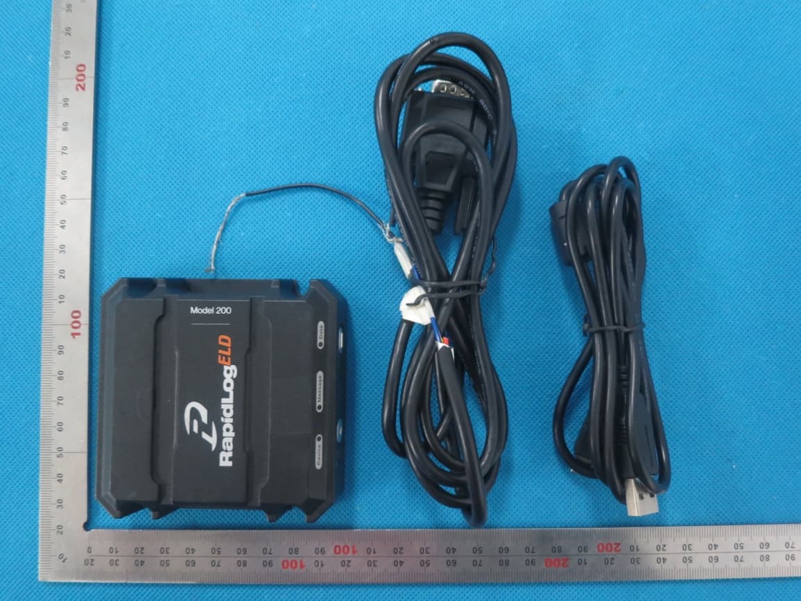
Click to zoom
Application Details
- Equipment Class
- PCB - PCS Licensed Transmitter
- Date of Grant
- Sep 16, 2015
- Application Purpose
- Original Equipment
- Date of Application
- Sep 16, 2015
- Equipment Note
- RapidLog ELD 200
- Frequency Range
- 1851.25000000 - 1908.75000000
- Country
- United States
Documents & Files
Document Text
Text extracted from the exhibit documents filed with the FCC. Open a document above to read the original.
Users Manual
RapidLog™ ELD 200 Owner’s Manual and Hardware Installation Guide IMPORTANT SAFETY INFORMATION To help prevent personal injury or loss of life: DO NOT install the unit: • If you’re not trained to safely connect to the truck’s power, ground and engine bus • Over airbag panels or within airbag inflation areas. • So it obstructs driver’s view of the road or the truck’s instruments and controls • Within 20 cm of the driver’s body DO install the unit: • Where the driver can easily and quickly see, hear and reach it while driving • So it’s firmly secured in place 1. Get an Activation File Activation files tie the ELD to a particular carrier and truck. After obtaining the RapidLog ELD app (see the Read Me First card for details), run it and click Activate in the lower left corner. You will need the included PIN card as well as details for the truck which will use this ELD: truck number, VIN, and number of pins on the diagnostic port. Internet access is required during this step, too. 2. Place the Dash-Top Unit Place the ELD on the dash where the driver can easily see, hear and reach it while driving. Dash mounting is strongly recommended for best GPS and wireless performance. Attach the included ELD cable to the back of the unit. Place two adhesive lock-strips on the ELD, and two on the dash in matching positions. Press the ELD down gently to lock it in place with the hooking lock-strips: 3. Run the Cable Run the cable under the dash so you can tap into power and the engine bus. Use the included zip ties to keep the cable secure; you can also press the cable between the dash and windshield for additional stability. Cut the cable to the appropriate length to reach all of the following: power, ground and the engine bus. Strip the end of the cable to reveal the six wires inside. 4. Connect Power Important! To prevent damage to your truck and the ELD (and potentially voiding your warranty), unplug the ELD cable from the back of the ELD while wiring power, ground and engine-bus connections. Connect the ELD cable’s ground (black) and power (red) wires to your truck’s ground and 12 volt power using the included insulation- displacement connectors (IDCs). If you are unfamiliar with IDCs, see Section 9. Be sure to wire power and ground correctly. The ELD contains a self-resetting fuse. 5. Connect the Engine Bus Look at your truck’s diagnostic port. If it has nine pins, you have a J1939 engine bus. If it has six pins, you have J1708. Most newer trucks have J1939. For J1939 connect the ELD cable’s J1939+ (yellow) and J1939- (green) anywhere along your truck’s matching J1939+ and J1939- wires using IDCs. If (and only if) your truck does NOT have J1939, you need to connect the ELD cable’s J1708+ (brown) and J1708- (orange) wires to your truck. Use IDCs to tap anywhere along your truck’s matching J1708+ and J1708- wires. Or use the included crimp- style female spade connectors to attach to your truck’s J1708 junction box. 6. Power the ELD Reattach the ELD cable to the ELD. The unit’s Device light should turn green. If the device is not responsive, disconnect the cable from the ELD, wait 60 seconds, and reattach. If it still is not functional double- check the power and ground connections. If problems persist, see Section 12. 7. Activate the ELD Run the RapidLog ELD app, and click Activate in the lower left corner of the Home page, and then click the Activate Device button. The activation file will be installed and the ELD will be tied to the truck and accessible only by authorized drivers and mechanics. If you encounter an error, see Section 12. 8. Test the Engine Bus Test the engine-bus connection by driving a short distance. The unit should sound an alarm since driving time has not been unlocked. The Quiet button should silence the alarm. If the alarm doesn’t sound, double check the engine bus connection and try again. If problems persist, see Section 12. Installation is now complete! 9. Using IDCs The included insulation-displacement connectors (IDCs) allow you to tap into your truck’s power, ground and engine bus without cutting wires. To use an IDC, make sure the silver connec- tor is raised, and has not been pushed down. If it has been pushed down, raise it back up using a staple-remover or other sharp tool. Good Bad To make a connection, place the correct wire from the truck (power, ground, engine bus, etc.) in the pass-through channel, and then fold the IDC half way to lock it onto that wire: Take the appropriate wire (no need to strip it) from the ELD cable and insert it fully into the IDC’s “tap” channel. Close the IDC completely using pliers and the connection is complete: Instructions continue... 10. Limited Warranty Eclipse Software Systems, LLC (ESS) warrants the RapidLog ELD to be free from defects in materials and workmanship for a period of one year from the date of first purchase. ESS will, without charge, repair or replace, at its option, defective products or component parts upon delivery to the ESS Factory Service Department, if accompanied by proof of the date of first purchase. Customer must pay any shipping charges required to ship the product for warranty service. Return shipping will be at ESS expense if the product is repaired or replaced under warranty. Exclusions: This Limited Warranty does not apply: (1) To products damaged by accident; (2) In the event of misuse or abuse of the product or as a result of unauthorized alterations/ repairs and/or improper installation; (3) If the serial number has been altered, defaced or removed; (4) If the owner of the produc- tresides outside the U.S.A. and Canada. NEITHER ESS NOR ANYONE ELSE WHO HAS BEEN INVOLVED IN THE CREATION, PRODUCTION, OR DELIVERY OF THIS PRODUCT SHALL BE LIABLE FOR ANY DIRECT, INDIRECT, CONSE- QUENTIAL, OR INCIDENTAL DAMAGES (INCLUDING DAMAGES FOR LOSS OF BUSINESS PROFITS, BUSINESS INTERRUPTION, LOSS OF BUSINESS INFORMATION, AND THE LIKE) ARISING OUT OF THE USE OR INABILITY TO USE SUCH DEVICE EVEN IF ESS HAS BEEN ADVISED…
Text truncated - open the document above for the full version.
Attestation Statements
Eclipse Software Systems, LLC 8201 W 20th Street ,Greeley,Colorado 80634, United States TEL: 970-353-6313 FAX: 970-353-6252 Ersteller: D. Brandhorst Revision: 00 Erstelldatum: 21.06.07 Datum: 00.00.00 Seite 1 von 1 Date: Aug.25, 2015 Subject: Ad Hoc Mode Function Declaration FCC ID: 2ADUX-ELD200 To Whom it may concern, This device is acting as slave device and operating in the 2.4 GHz (2412 – 2462 MHz) band. Ad Hoc function is supported but not able to operate on non-US frequencies. Please contact the one signed below or the authorized agent for this filing. Thank you. Regards, Company Officer: Larry Steinbecker Telephone Number: 970-353-6313 Email: [email protected]
Cover Letter(s)
Eclipse Software Systems, LLC 8201 W 20th Street ,Greeley,Colorado 80634, United States TEL: 970-353-6313 FAX: 970-353-6252 Date (25/08/2015) TUV SUD BABT TCB Octagon House, Segensworth Road, Fareham, Hampshire, PO15 5RL Confidentiality Request FCC ID: 2ADUX-ELD200 Pursuant to Sections 0.457(d)(1)(ii) and 0.459 of the Commission’s Rules, Eclipse Software Systems, LLC hereby requests permanent confidential treatment of information accompanying this application as outlined below: 1.Schematics 2.Bill of Materials/Parts List 3.Block Diagrams 4.Theory of Operation 5.Tune Up Procedure The above materials contain trade secrets and proprietary information not customarily released to the public. The public disclosure of these matters might be harmful to the Applicant and provide unjustified benefits to its competitors. The Applicant understands that pursuant to Rule 0.457(d)(1)(ii), disclosure of this Application and all accompanying materials will not be made before the date of the Grant for this Application. Yours sincerely, Company Officer: Larry Steinbecker Telephone Number: 970-353-6313 Email: [email protected]
External Photos
External Photos TOTAL VIEW OF EUT TOP VIEW OF EUT BOTTOM VIEW OF EUT FRONT VIEW OF EUT BACK VIEW OF EUT LEFT VIEW OF EUT RIGHT VIEW OF EUT
ID Label/Location Info
FCC ID Label Location RapidLog ELD 200 Model:200 FCC ID: 2ADUX-ELD200 FCC ID: 2ADUX-ELD200
Internal Photos
Internal Photos OPEN VIEW OF EUT‐1 CDMA Antenna OPEN VIEW OF EUT‐2 OPEN VIEW OF EUT‐3 INTERNAL VIEW OF EUT‐1 INTERNAL VIEW OF EUT‐2 INTERNAL VIEW OF EUT‐3 INTERNAL VIEW OF EUT‐4 WIFI Antenna
RF Exposure Info
RF EXPOSURE Product name: RapidLog ELD 200 Brand name: RapidLog Model name:200 FCC ID: 2ADUX-ELD200 1. RF EXPOSURE MEASUREMENT 1.1 INTRODUCTION Human exposure to RF emissions from mobile devices (47 CFR §2.1091) may be evaluated based on the MPE limits adopted by the FCC for electric and magnetic field strength and/or power density, as appropriate, since exposures are assumed to occur at distances of 2.5 cm or more from persons. The 1992 ANSI/IEEE standard (See Listed limit table) specifies a minimum separation distance of 1cm for performing reliable field measurements to determine adherence to MPE limits. If the minimum separation distance between a transmitter and nearby persons is more than 2.5 cm under normal operating conditions, compliance with MPE limits may be determined at such distance from the transmitter. When applicable, operation instructions and prominent warning labels may be used to alert the exposed persons to maintain a specified distance from the transmitter or to limit their exposure durations and usage conditions to ensure compliance. 1.2 FCC LIMITS FOR MAXIMUM PERMISSIBLE EXPOSURE(MPE) LIMITS FOR GENERAL POPULATION / CONTROLLED EXPOSURE Frequency Range (MHz) E-field Strength (E) (V/m) Magnetic Field Strength (H) (A/m) Power Density (S) (mW/cm 2 ) Averaging Time |E| 2 , |H| 2 or S (Minutes) 0.3 -- 1.34 614 1.63 (100)* 6 1.34 -- 30 824/f 4.89/f (900/f 2 )* 6 30 -- 300 61.4 0.163 1.0 6 300 -- 1500 -- -- f/300 6 1500 -- 100,000 -- -- 5 6 *Note: 1. f=Frequency in MHz * Plane-wave Equivalent Power Density. 2. CLASSIFICATION OF THE ASSESSMENT METHODS According to user manual,The antenna of the product, under normal use condition is at least 0.2m away from the body of the user. Warning statement to the user for keeping at least 0.2m separation distance and the prohibition of operating to a person has been printed on the user’smanual. So, this product under normal use is located on electromagnetic far field betweenthe human body. S=PG/4πR² Where: S=power density P=power input to antenna G=power gain of the antenna in the direction of interest relative to an isotropic radiator R=distance to the center of radiation of the antenna 3. EUT OPERATION CONDITION Make the EUT to transmit at lowest, middle and highest channel individually. 4. TEST RESULTS Antenna Gain1.2dBi (Numeric 1.32), π=3.1416 CDMA 2000 BC0/ CDMA2000 1xEV-DO: Channel Frequency Output Power (peak) Output Power (peak) Power Density Power Density Limit Result MHz dBm mW mW/cm2 mW/cm2 Pass/Fail L 824.7 23.56 226.99 0.060 2.75 Pass M 836.52 23.76 237.68 0.062 2.79 Pass H 848.31 23.61 229.61 0.060 2.83 Pass CDMA 2000 BC1/ CDMA2000 1xEV-DO: Channel Frequency Output Power (peak) Output Power (peak) Power Density Power Density Limit Result MHz dBm mW mW/cm2 mW/cm2 Pass/Fail L 1851.25 23.69 233.88 0.061 5 Pass M 1880 23.58 228.03 0.060 5 Pass H 1908.75 23.54 225.94 0.059 5 Pass Note:The distance between users and EUT is 0.2m.
Test Report
Any reproduction of this document must be done in full. No single part of this document may be reproduced without permission from STS, All Test Data Presented in this report is only applicable to presented Test sample. Shenzhen STS Test Services Co., Ltd. 1/F, Building B, Zhuoke Science Park, Chongqing Road, Fuyong, Baoan District, Shenzhen, China TEL: +86-755 3688 6288 FAX: +86-755 3688 6277 E-mail:[email protected] FCC TEST REPORT Report No: STS1503015F01 Issued for Eclipse Software Systems, LLC 8201 W 20th Street – Greeley, CO 80634 Product Name: RapidLog ELD 200 Brand Name: RapidLog Model No.: 200 Series Model: N/A FCC ID: 2ADUX-ELD200 Test Standard: FCC Part 2,22,24 S T L A B S Page 2 of 57 Report No.: STS1503015F01 TEST RESULT CERTIFICATION Applicant’s name .................... Eclipse Software Systems, LLC Address .................................... 8201 W 20th Street – Greeley, CO 80634 Manufacture's Name .............. Shenzhen Unistrong Science & Technology Co., Ltd. Address .................................... No.4, Zhengcheng 2nd Rd., Xintian Village, Fuyong Town, Bao'an District, Shenzhen, China Product description Product name ........................... RapidLog ELD 200 Band name ............................... RapidLog Model and/or type reference ..... 200 Standards ................................ FCC Part 2,22,24 Test procedure .......................... .ANSI C63.4-2009 This device described above has been tested by STS, and the test results show that the equipment under test (EUT) is in compliance with the FCC requirements. And it is applicable only to the tested sample identified in the report. This report shall not be reproduced except in full, without the written approval of STS, this document may be altered or revised by STS, personal only, and shall be noted in the revision of the document. Date of Test .............................. . Date of performance of tests .... . 01 Mar. 2015 ~15 July 2015 Date of Issue ............................ . 16 July 2015 Test Result ................................ .Pass Testing Engineer : (Hakim Hou) Report writing : (Sunny zheng) Authorized Signatory : (Bovey Yang) Page 3 of 57 Report No.: STS1503015F01 Table of Contents Page 1. SUMMARY OF TEST RESULTS 5 1.1 TEST FACILITY 5 1.2 MEASUREMENT UNCERTAINTY 5 2. GENERAL INFORMATION 6 2.1 GENERAL DESCRIPTION OF EUT 6 2.2 DESCRIPTION OF TEST MODES 7 2.3 BLOCK DIGRAM SHOWING THE CONFIGURATION OF SYSTEM TESTED 7 2.4 DESCRIPTION OF SUPPORT UNITS 8 2.5 EQUIPMENTS LIST FOR ALL TEST ITEMS 9 3. OUTPUT POWER 10 3.1 CONDUCTED OUTPUT POWER 10 3.1.1 MEASUREMENT METHOD 10 3.1.2 MEASUREMENT RESULT 10 3.2 RADIATED OUTPUT POWER 14 3.2.1 MEASUREMENT METHOD 14 3.2.2 PROVISIONS APPLICABLE 14 3.2.3 MEASUREMENT RESULT 15 3.3. PEAK-TO-AVERAGE RATIO 16 3.3.1 MEASUREMENT METHOD 16 3.3.2 PROVISIONS APPLICABLE 16 3.3.3 MEASUREMENT RESULT 16 4. SPURIOUS EMISSION 17 4.1 CONDUCTED SPURIOUS EMISSION 17 4.1.1 MEASUREMENT METHOD 17 4.1.2 PROVISIONS APPLICABLE 17 4.1.3 MEASUREMENT RESULT 17 4.2 RADIATED SPURIOUS EMISSION 18 4.2.1 MEASUREMENT METHOD 18 4.2.2 PROVISIONS APPLICABLE 19 4.2.3 MEASUREMENT RESULT 20 5. MAINS CONDUCTED EMISSION 21 5.1 MEASUREMENT METHOD 21 5.2 PROVISIONS APPLICABLE 21 5.3 MEASUREMENT RESULT 22 6. FREQUENCY STABILITY 24 6.1 MEASUREMENT METHOD 24 Page 4 of 57 Report No.: STS1503015F01 Table of Contents Page 6.2 PROVISIONS APPLICABLE 24 6.2.1 FOR HAND CARRIED BATTERY POWERED EQUIPMENT 24 6.2.2 FOR EQUIPMENT POWERED BY PRIMARY SUPPLY VOLTAGE 25 6.3 MEASUREMENT RESULT (WORST) 25 7. OCCUPIED BANDWIDTH 27 7.1 MEASUREMENT METHOD 27 7.2 PROVISIONS APPLICABLE 27 7.3 MEASUREMENT RESULT 27 8. EMISSION BANDWIDTH 28 8.1 MEASUREMENT METHOD 28 8.2 PROVISIONS APPLICABLE 28 8.3 MEASUREMENT RESULT 28 9. BAND EDGE 29 9.1 MEASUREMENT METHOD 29 9.2 PROVISIONS APPLICABLE 29 9.3 MEASUREMENT RESULT 29 Page 5 of 57 Report No.: STS1503015F01 1. SUMMARY OF TEST RESULTS Test procedures according to the technical standards: Item Description FCC Rules Result Output Power Conducted Output Power 2.1046/22.913(a) (2) / 24.232 (c) Pass Radiated Output Power Peak-to-Average Ratio Peak-to-Average Ratio 24.232(d) Pass Spurious Emission Conducted Spurious Emission 2.1051/2.1053/22.917(a)/24.238(a) Pass Radiated Spurious Emission Mains Conducted Emission 15.107 / 15.207 Pass Frequency Stability 2.1055/22.355 /24.235 Pass Occupied Bandwidth 2.1049 (h)(i) Pass Emission Bandwidth 22.917(a)/24.238(a) Pass Band Edge 2.1051/22.917(a)/24.238(a) Pass NOTE: (1)” N/A” denotes test is not applicable in this Test Report 1.1 TEST FACILITY Shenzhen STS Test Services Co., Ltd. Add.: 1/F, Building 2, Zhuoke Science Park, Chongqing Road, Fuyong, Baoan District, Shenzhen, China. FCC Registration No.: 842334 1.2 MEASUREMENT UNCERTAINTY The reported uncertainty of measurement y ± U,where expended uncertainty U is based on a standard uncertainty multiplied by a coverage factor of k=2,providing a level of confidence of approximately 95 %。 No. Item Uncertainty 1 Conducted Emission Test ±1.38dB 2 RF power,conducted ±0.16dB 3 Spurious emissions,conducted ±0.21dB 4 All emissions,radiated(<1G) ±4.68dB 5 All emissions,radiated(>1G) ±4.89dB 6 Temperature ±0.5°C 7 Humidity ±2% Page 6 of 57 Report No.: STS1503015F01 2. GENERAL INFORMATION 2.1 GENERAL DESCRIPTION OF EUT Equipment RapidLog ELD 200 Trade Name RapidLog Model Name 200 Serial Model N/A Model Difference N/A Rating Voltage DC 12V Hardware version number E9616_V1.3 Software versioning number V2.8 I/O Port of EUT I/O Port Type Q’TY Cable Tested with DC INPUT PORT 1 0.8m, unshielded 1 USB PORT 2 0.8m, unshielded 1 Note: 1. For a more detailed features description, please refer to the manufacturer’s specifications or the User's Manual. Page 7 of 57 Report No.: STS1503015F01 2.2 DESCRIPTION OF TEST MODES During the testing, the EUT was controlled via Rhode & Schwarz Digital Radio Communication Tester (CMU 200/ AGILENT 8960) to ensure max power transmission and proper modulation. Three channels (The top channe…
Text truncated - open the document above for the full version.
Test Setup Photos
APPENDIX IV PHOTOGRAPHS OF TEST SETUP CONDUCTED EMISSION RADIATED SPURIOUS EMISSION
Contact Information
Applicant
Larry Steinbecker
Test Firm
Shenzhen STS Test Services Co., Ltd.Bovey Yang
Technical Specifications
| # | Rule Parts | Frequency Range | Power Output | Emission | Tolerance |
|---|---|---|---|---|---|
| 2 | 24E | 1.85 GHz - 1.91 GHz | 230.00 mW | 1M45F9W | 0.02 ppm |