2ADXY59502Induction Buffet Warmer
The Vollrath Company, LLC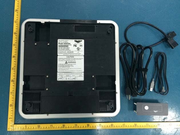
Click to zoom
Application Details
- Equipment Class
- 8CC - Part 18 Consumer Device
- Date of Grant
- Feb 01, 2015
- Application Purpose
- Original Equipment
- Date of Application
- Jan 31, 2015
- Equipment Note
- Induction Buffet Warmer
- Frequency Range
- 0.01800000 - 0.06200000
- Company
- The Vollrath Company, LLC
- Country
- United States
Documents & Files
Document Text
Text extracted from the exhibit documents filed with the FCC. Open a document above to read the original.
Users Manual
Draft Copy ENGLISH Operators Manual Item No.2350248-1Rev1/28/15 Mirage® Buffet induction WarMers Thank you for purchasing this Vollrath Induction Range. Before operating the equipment, read and familiarize yourself with the following operating and safety instructions. SAVE THESE INSTRUCTIONS FOR FUTURE REFERENCE. Save the original box and packaging. Use this packaging to ship the equipment if repairs are needed. itemModeldescriptiondimensionsVoltageHzWattsampsPlug 5950275 595 Countertop Buffet Induction Warmer - Black 16" x 16" x 3" (40.6 x 40.6 x 7.6 cm) 120 50/60300 2.55-15P 595027502 2201.3 Schuko 595027503 UK 595027504 China 595027505 Australia 5950280 595 Countertop Buffet Induction Warmer - Natural 16" x 16" x 3" (40.6 x 40.6 x 7.6 cm) 120 50/60300 2.55-15P 595028002 2301.3 Schuko 595028003 UK 595028004 China 595028005 Australia 59502DW 595 Drop-in Buffet Induction Warmer 16" x 16" x 3" (40.6 x 40.6 x 7.6 cm) 120 50/60300 2.55-15P 59502DW02 2301.3 Schuko 59502DW03 UK 59502DW04 China 59502DW05 Australia Draft Copy OperatOr’s Manual 2 ENGLISH Safety PrecautionS To ensure safe operation, read the following statements and understand their meaning. This manual contains safety precautions which are explained below. Please read carefully. Warning Warning is used to indicate the presence of a hazard that will or can cause severe personal injury or death. caution Caution is used to indicate the presence of a hazard that will or can cause minor or major personal injury if the caution is ignored. NOTICE: is used to note information that is important but not hazard- related. These precautions should be followed at all times. Failure to follow these precautions could result in injury to yourself and others. Plug only into grounded electrical outlets matching the nameplate rated voltage. As a precaution, persons using a pacemaker should stand back 12” (30 cm) from an operating unit. Studies have shown that the induction element will not disrupt a pacemaker. Keep all credit cards, driver license and other items with a magnetic strip away from an operating unit. The unit’s magnetic field will damage the information on these strips. The heating surface is made of a strong, non-porous material. However, should it crack or break, stop using and immediately unplug the unit. Do not leave an empty pan on an operating unit. Unit should only be used in a flat, level position. Unplug unit and let it cool before cleaning or moving. Do not touch the heating surface. It remains hot after the unit is turned off. Unplug when not in use. Keep unit and power cord away from open flames, electric burners or excessive heat. Do not heat sealed cans or containers as they may explode. Do not operate unattended. Closely supervise units operating in public areas and/or around children. Do not operate if unit has been damaged or is malfunctioning in any way. Do not place any objects inside the air intake or exhaust panels. fcc Statement This equipment has been tested and found to comply with Part 18 of FCC Rules. These limits are designed to provide reasonable protection against harmful interference in a residential installation. This equipment generates, uses and can radiate radio frequency energy and, if not installed and used in accordance with the instructions, may cause harmful interference to radio communications. However, there is no guarantee that interference will not occur in a particular installation. If this equipment does cause harmful interference to radio or television reception, which can be determined by turning the equipment off and on, the user is encouraged to try to correct the interference by one or more of the following measures: Reorient or relocate the receiving antenna Increase the separation between the equipment and receiver Connect the equipment into an outlet on a circuit different from that to which the receiver is connected Consult the dealer or an experienced radio/TV technician for help To assure continued compliance, any changes or modifications not expressly approved by the party Responsible for compliance could void the user’s authority to operate this equipment. (Example- use only shielded interface cables when connecting to computer or peripheral devices). function and PurPoSe This unit is intended to hold heated prepared food at serving temperatures. It is intended for use in commercial foodservice operations only. It is not intended for household, industrial or laboratory use. This unit is intended to be used with induction-ready serving vessels. induction ready Serving veSSel Flat base measuring 4-1/2” (11.4 cm) to 10-1/4” (26 cm) wide Ferrous stainless steel Iron Cast iron unSuitable Serving veSSel Serving vessel with a base less than 4-1/2" (11.4 cm) Pottery, glass, aluminum, bronze or copper serving vessels Serving vessel with any type of footed base countertoP Warmer inStallation clearance requirementS This unit is not designed to be enclosed or built into any area. There must be a minimum clear space of : • 4" (10 cm) between the back of the warmer and any surrounding surface • 2" (5.1 cm) between the sides of the warmer and any surrounding surface • Under the warmer, a distance equal to the height of the feet of the warmer. Sufficient airflow must be allowed around the unit. Warmer must not be placed on a soft surface that could restrict airflow to the bottom of the warmer. Blocking the airflow could cause the unit to overheat. inStallation 1. Place the unit on a hard,flat stable surface. 2. Plug the power cord into a grounded electrical outlet with the matching nameplate rated voltage. NOTICE: Using a voltage other than the nameplate rated voltage will cause damage to the unit. Incorrect voltage, modification to the power cord or electrical components can damage unit and will void the warranty. Draft Copy 3 ENGLISH OperatOr’s Manual droP-in Warmer inStallation Drop-in Mirage® Buffet Induction Warmers can be installed with the top of the warmer o…
Text truncated - open the document above for the full version.
External Photos
Report No.: TB-FCC142966 Page: 3 of 16 TB-RF-075-1.0 Appendix III EUT External Photographs Photo 1 Appearance of EUT Photo 2 Appearance of EUT Report No.: TB-FCC142966 Page: 4 of 16 TB-RF-075-1.0 Photo 3 Appearance of EUT Photo 4 Appearance of EUT Report No.: TB-FCC142966 Page: 5 of 16 TB-RF-075-1.0 Photo 5 Appearance of EUT Photo 6 Appearance of EUT
ID Label/Location Info
Report No.: TB-FCC142966 Page: 1 of 16 TB-RF-074-1.0 Appendix IFCC ID Label ID Label of Model: 5950275: ID Label of Model: 5950280: ID Label of Model: 59502DW:
ID Label/Location Info
Report No.: TB-FCC142966 Page: 2 of 16 TB-RF-075-1.0 Appendix II ID Label Location ID LOCATION
Internal Photos
Report No.: TB-FCC142966 Page: 6 of 16 TB-RF-075-1.0 Appendix IV EUT Internal Photographs Photo 7 Internal of EUT Photo 8 Internal of EUT Report No.: TB-FCC142966 Page: 7 of 16 TB-RF-075-1.0 Photo 9 Appearance of Coil Photo 10 Appearance of Coil Report No.: TB-FCC142966 Page: 8 of 16 TB-RF-075-1.0 Photo 11 Internal of EUT Photo 12 Internal of EUT Report No.: TB-FCC142966 Page: 9 of 16 TB-RF-075-1.0 Photo 13 Appearance of Main Board Photo 14 Appearance of Main Board Report No.: TB-FCC142966 Page: 10 of 16 TB-RF-075-1.0 Photo 15 Appearance of EMI Board Photo 16 Appearance of EMI Board Report No.: TB-FCC142966 Page: 11 of 16 TB-RF-075-1.0 Photo 17 Appearance of EMI Board Photo 18 Appearance of Top Display Board Report No.: TB-FCC142966 Page: 12 of 16 TB-RF-075-1.0 Photo 19 Appearance of Top Display Board Photo 20 Appearance of Front Display & Key Board Report No.: TB-FCC142966 Page: 13 of 16 TB-RF-075-1.0 Photo 21 Appearance of Front Display & Key Board Photo 22 Internal of Control Box Display Board Report No.: TB-FCC142966 Page: 14 of 16 TB-RF-075-1.0 Photo 23 Appearance of Control Box Display Board Photo 24 Appearance of Control Box Display Board
Test Report
Shenzhen Toby Technology Co., Ltd. Report No.: TB-FCC142966 Page: 1 of 21 TB-RF-074-1.0 1A/F., Bldg.6, Yusheng Industrial Zone, The National Road No.107 Xixiang Section 467, Xixiang, Bao’an, Shenzhen, China Tel: +86 75526509301 Fax: +86 75526509195 FCC Test Report FCC ID: 2ADXY59502 Original Grant Report No. : TB-FCC142966 Applicant : The Vollrath Company, LLC Equipment Under Test (EUT) EUT Name : Buffet Induction Warmer Model No. : 5950275 Series Model No. : 5950280, 59502DW Brand Name : VOLLRATH Receipt Date : 2014-12-29 Test Date : 2014-12-29 to 2015-01-15 Issue Date : 2015-01-19 Standards : FCC Part 18 : 2014 Conclusions : PASS In the configuration tested, the EUT complied with the standards specified above, The EUT technically complies with the FCC requirements Test/Witness Engineer : Approved& Authorized : This report details the results of the testing carried out on one sample. The results contained in this test report do not relate to other samples of the same product. The manufacturer should ensure that all products in series production are in conformity with the product sample detailed in the report. Report No.: TB-FCC142966 Page: 2 of 21 TB-RF-074-1.0 Contents CONTENTS ............................................................................................................................................. 2 1. GENERAL INFORMATION ABOUT EUT ............................................................................. 3 1.1 Client Information ................................................................................................................. 3 1.2 General Description of EUT (Equipment Under Test) ................................................... 3 1.3 Block Diagram Showing the Configuration of System Tested ...................................... 3 1.4 Description of Support Units .............................................................................................. 4 1.5 Description of Test Mode .................................................................................................... 4 1.6 Test Location ........................................................................................................................ 4 2. TEST SUMMARY ....................................................................................................................... 5 3. CONDUCTED EMISSION TEST ............................................................................................. 6 3.1 Test Standard and Limit ...................................................................................................... 6 3.2 Test Setup ............................................................................................................................. 6 3.3 Test Procedure ..................................................................................................................... 6 3.4 Deviation ............................................................................................................................... 7 3.5 Test Equipment Used .......................................................................................................... 7 3.6 Test Data ............................................................................................................................... 7 4. RADIATED EMISSION TEST ................................................................................................ 12 4.1 Test Standard and Limit .................................................................................................... 12 4.2 Test Setup ........................................................................................................................... 12 4.3 Test Procedure ................................................................................................................... 12 4.4 Deviation ............................................................................................................................. 12 4.5 Test Equipment .................................................................................................................. 13 4.6 Test Data ............................................................................................................................. 13 Report No.: TB-FCC142966 Page: 3 of 21 TB-RF-074-1.0 1. General Information about EUT 1.1 Client Information Applicant : The Vollrath Company, LLC Address : 1236 North 18th Street, Sheboygan, WI 53081 Manufacturer : Luxine (Xi’an) Electronics Co., Ltd. Address : 4th Floor, Building B, Seeker Industrial Park, 2nd Jin Ye Rd, Hi-tech Development Zone, Xi'an Shaanxi, China 710075 1.2 General Description of EUT (Equipment Under Test) EUT Name : Buffet Induction Warmer Models No. : 5950275, 5950280, 59502DW Model difference : All these models are identical in the same PCB, layout and electrical circuit, the only difference is the color of the appearance and installation: 5950275: Countertop, Black; 5950280: Countertop, Natural; 59502DW: Drop-in, added a remote control box, connected by a USB cable. Power Supply : AC 120V, 60Hz Power : One unit maximum power: 320W Three units maximum power: 960W Connecting I/O Port(s) : Please refer to the User's Manual Note: For a more detailed features description, please refer to the manufacturer’s specifications or the User’s Manual. 1.3 Block Diagram Showing the Configuration of System Tested One Unit Working AC Power Three Units Working AC Power Report No.: TB-FCC142966 Page: 4 of 21 TB-RF-074-1.0 1.4 Description of Support Units The EUT has been tested with water up to 80% of the maximum capacity of the boiler. 1.5 Description of Test Mode To investigate the maximum EMI emission characteristics generates from EUT, the test system was pre-scanning tested base on the consideration of the EUT operation mode, and the worst Case is when the EUT is operation with the maximum power, so the conducted and radiated emission data of bellow only showed the worst case. 1.6 Test Locati…
Text truncated - open the document above for the full version.
Test Setup Photos
Report No.: TB-FCC142966 Page: 15 of 16 TB-RF-075-1.0 Appendix V EUT Test Photographs Radiation Test Setup Photo of Setup for Radiated Emission (One Unit) Photo of Setup for Radiated Emission (Three Units) Report No.: TB-FCC142966 Page: 16 of 16 TB-RF-075-1.0 Conduction Test Setup Photo of Setup for Conducted Emission (One Unit) Photo of Setup for Conducted Emission (Three Units)
Contact Information
Applicant
Ryan Zhang(Engineer)
Test Firm
Shenzhen Toby Technology Co., Ltd.Justin Zhang
Technical Specifications
| # | Rule Parts | Frequency Range | Power Output |
|---|---|---|---|
| 1 | 18 | 0.018 MHz - 0.062 MHz | - |