2ADZ7MGS10102Carbon ARM
ThinPAD Technology (ShenZhen) Co.,Ltd.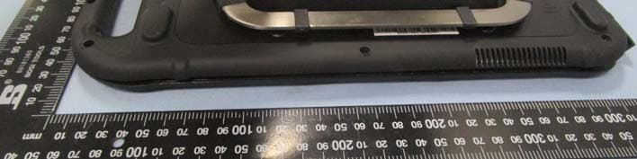
Click to zoom
Application Details
- Equipment Class
- DTS - Digital Transmission System
- Date of Grant
- Feb 12, 2015
- Application Purpose
- Original Equipment
- Date of Application
- Feb 12, 2015
- Equipment Note
- Carbon ARM
- Frequency Range
- 2402.00000000 - 2480.00000000
- Country
- China
Documents & Files
Document Text
Text extracted from the exhibit documents filed with the FCC. Open a document above to read the original.
Users Manual
1 Carbon User Manual 2 Table of contents First Steps................................................................ 3 Introduction.......................................................... 4 Getting to know your tablet............................. 5 Front View......................................................... 5 Rear View.......................................................... 7 Top View.......................................................... .. 8 Bottom View.................................................... .. 9 Side Views......................................................... 10 Packing List ................................................. ...... 11 Optional Accessories........................................ 12 Getting Started.................................................... 13 Connecting the AC Power................................ .. 13 Turning the tablet on and off........................ ... 14 The optimised use for sunlight readable touch screen................................................15 3 First Steps This manual will help you get the most from your tablet. Please read it carefully before starting Let your tablet acclimatise itself Do not power up your tablet immediately if it has been exposed to hot or cold conditions. Instead, allow it to adjust gradually to room temperature over a three to four hour period. Please note that you must fully charge the battery before using your tablet. Where to use your tablet Your tablet will run well under most conditions but avoid extreme temperatures and humidity levels. Allow sufficient air circulation around the computer when you are working indoors to prevent overheating. Do not block the ventilation opening or place your tablet in direct sunlight. There are some things you can tolerate that your tablet can’t – things like static electricity, dust, water, steam and oil. 4 WARNING - Never try to disassemble or back engineer your tablet as we will not be responsible for any damage caused if you do so and this action would void your warranty Introduction Your tablet features the latest advances in portable computing technology with a modular design that provides maximum expandability without compromising portability. Please note that some of the features mentioned in this manual might not be included on your tablet or may vary slightly. Unpacking your tablet Your tablet comes securely packaged in a shipping carton. Please contact your supplier if you find that anything is missing or damaged after examining the contents. Do not throw the packaging materials away. You may need them later if you have to ship the computer. What is in the box Tablet PC Getting to know your tablet 5 Front View with Capacitive touch panel 6 1. LCD Panel This tablet is equipped with a 10.1” LCD display with a resolution of up to 1280 x 800 2. Speaker Two Piezoelectric speaker 3. Reset Function Hall IC switch on handle(EC Control) – External magnet action 7 Right Side View 4. Wi-Fi Indicator & Power LED 5.1 WIFI Indicator Lights up Green when the Wi-Fi device is turned on. Light will flicking when data transferring No light when Wi-Fi stops operation 5.2 Power Indicator Blue: Connect to DC Power No Light: No DC Power Flash: System standby 5. Lock LED: Controlled by Power Crate Device location U30 change of status White LED Slid in to Power Crate Magnet in locking arm moving into detection range of U30 2 second pulse white LED Locked in Power Crate Magnet still in detected range OFF Unlocked from Power Crate Magnet in locking arm Leaving detection range of U30 Flashing(1 second on/1 second off) for 10 seconds Removed Power Crate No Magnet detected OFF Slid in to Power Crate the most of charging On Note: When Device removed from Power Crate, EC must set PCA9555 PIN4 to “High” 8 6. Battery Indicator Status Red Amber GREEN Charge(S0,S3,S5) 0%-40% Flash OFF OFF 41%-80% OFF Flash OFF 81%-100% OFF OFF Flash No Charge (S0) 0%-40% ON OFF OFF 41%-80% OFF ON OFF 81%-100% OFF OFF ON No Charge (S3,S5) 0%-40% OFF OFF OFF 41%-80% OFF OFF OFF 81%-100% OFF OFF OFF Note: Battery charge current had 3 level can be selected. Low voltage charge: 0.368A; Normal Charge: 2A; Fast charge: 4A. And the charge current behaviors selected base on customer requirement. 9 Rear View with 8000mAh battery 10 Rear View with 16000mAh battery 11 7. Lock hole For Kingston locker 8. Rear facing 5Mega Pixel with auto flash and LED flash 9. VESA Mounting 10. WIFI Logo IEEE 802.11b/g/n/ Wireless card with WIFI Antenna 11. Kick stand Integrated rear friction grip kickstand for use in both landscape & portrait orientation, with Indexing for portrait. 12 12. SIM Card Slot Slot for fitting a SIM Card 13. Micro-SD Slot Slot for fitting a Micro-SD card 14. DC Jack DC jack port for charging the tablet (12V --- 4A). 15. Pogo connector For changing the tablet when used with a docking station 16. HDMI / LAN Mini HDMI for fast earth net (10/100) via HDMI to LAN cable. 17. USB 2.0 port Mini USB 2.0 hidden port 18. 3.5mm audio Jack For headphone insert. 19. Power Button Power button to turn the tablet on 13 Packaging list This product is shipped with the items list below. Please make sure that all are in Gift box. 1 piece of Rugged Tablet PC 14 Getting Started This chapter guides you to get the tablet ready for operating. Connecting the AC Power Our tablet PC can operate either on the external AC power adapter or internal battery power. It is suggested that you use AC power when you start up the tablet PC first time. 1. Plug the DC cord of the AC adapter to the power connector of the tablet PC. 2. Plug the female end of the AC power cord to the AC adapter and the male end to the power electrical outlet. 3. When the AC adapter is connected, the Battery Pack is also charging. You can check the Battery Status LED indicator to see the current progress. The indicator turns to green when it is fully charged. Caution - Use only the AC adapter included with your tablet PC. Using other AC adapters may dam…
Text truncated - open the document above for the full version.
External Photos
ThinPAD Technology (ShenZhen) Co., Ltd. Model: MGS101-02 REPORT NO.: STRD1411094I-1/2/3 FCC PART 15.247 EXHIBIT 2 - EUT EXTERNAL PHOTOGRAPHS EUT View 1 EUT View 2 ThinPAD Technology (ShenZhen) Co., Ltd. Model: MGS101-02 REPORT NO.: STRD1411094I-1/2/3 FCC PART 15.247 EUT View 3 EUT View 4 ThinPAD Technology (ShenZhen) Co., Ltd. Model: MGS101-02 REPORT NO.: STRD1411094I-1/2/3 FCC PART 15.247 EUT View 5 EUT View 6
ID Label/Location Info
ThinPAD Technology (ShenZhen) Co., Ltd. Model: MGS101-02 REPORT NO.: STRD1411094I-1/2/3 FCC PART 15.247 EXHIBIT 1 - PRODUCT LABELING Proposed FCC ID Label Format Specifications: Text is Black in color and justified. Labels are printed in indelible ink on permanent adhesive silk-screened onto the EUT or shall be affixed at a conspicuous location on the EUT. Proposed Label Location on EUT FCC ID Label Location
ID Label/Location Info
ThinPAD Technology (ShenZhen) Co., Ltd. Model: MGS101-02 REPORT NO.: STRD1411094I-1/2/3 FCC PART 15.247 EXHIBIT 1 - PRODUCT LABELING Proposed FCC ID Label Format Specifications: Text is Black in color and justified. Labels are printed in indelible ink on permanent adhesive silk-screened onto the EUT or shall be affixed at a conspicuous location on the EUT. Proposed Label Location on EUT FCC ID Label Location
Internal Photos
ThinPAD Technology (ShenZhen) Co., Ltd. Model: MGS101-02 REPORT NO.: STRD1411094I-1/2/3 FCC PART 15.247 EXHIBIT 3 - EUT INTERNAL PHOTOGRAPHS EUT Housing and Board View 1 Solder Board-Component View 1 Wi-Fi/BT Antenna ThinPAD Technology (ShenZhen) Co., Ltd. Model: MGS101-02 REPORT NO.: STRD1411094I-1/2/3 FCC PART 15.247 Solder Board-Component View 2 Solder Board-Component View 3 ThinPAD Technology (ShenZhen) Co., Ltd. Model: MGS101-02 REPORT NO.: STRD1411094I-1/2/3 FCC PART 15.247 Solder Board-Component View 4 Solder Board-Component View 5 ThinPAD Technology (ShenZhen) Co., Ltd. Model: MGS101-02 REPORT NO.: STRD1411094I-1/2/3 FCC PART 15.247 Solder Board-Component View 6 Solder Board-Component View 7
Internal Photos
ThinPAD Technology (ShenZhen) Co., Ltd. Model: MGS101-02 REPORT NO.: STRD1411094I-1/2/3 FCC PART 15.247 Solder Board-Component View 8 Solder Board-Component View 9 ThinPAD Technology (ShenZhen) Co., Ltd. Model: MGS101-02 REPORT NO.: STRD1411094I-1/2/3 FCC PART 15.247 Solder Board-Component View 10 Solder Board-Component View 11 ThinPAD Technology (ShenZhen) Co., Ltd. Model: MGS101-02 REPORT NO.: STRD1411094I-1/2/3 FCC PART 15.247 Solder Board-Component View 12 Solder Board-Component View 13 ThinPAD Technology (ShenZhen) Co., Ltd. Model: MGS101-02 REPORT NO.: STRD1411094I-1/2/3 FCC PART 15.247 Solder Board-Component View 14
RF Exposure Info
F Exposure Requirements Product Description: Carbon ARM Model No.: MGS101-02 FCC ID: 2ADZ7MGS10102 According to the KDB 447498 D01 V05r02, the following RF exposure evaluation shall to demonstrate RF exposure compliance. For Wi-Fi (802.11b/g/n) Tx frequency range: 2412-2472MHz Device category: Portable device (Distance: 5mm) Maximum Conducted Output Power: 9.23dBm Maximum Output Power: 8.38mW Limit: 10mW Source-based time-averaged output power is 8.38mW < 10mW For BT (EDR mode) Tx frequency range: 2402-2480MHz Device category: Portable device (Distance: 5mm) Maximum Conducted Output Power: -7.46dBm Maximum Output Power: 0.18mW Limit: 10mW Source-based time-averaged output power is 0.18mW < 10mW For BT (BLE mode) Tx frequency range: 2402-2480MHz Device category: Portable device (Distance: 5mm) Maximum Conducted Output Power: 1.525dBm Maximum Output Power: 1.42mW Limit: 10mW Source-based time-averaged output power is 1.42mW < 10mW So the transmitter complies with the RF exposure requirements and the SAR is not required.
Test Report
ThinPAD Technology (ShenZhen) Co., Ltd. Model: MGS101-02 REPORT NO.: STRD1411094I-3 PAGE 1 OF 36 FCC PART 15.247 FCC Part 15C Measurement and Test Report For ThinPAD Technology (ShenZhen) Co., Ltd. Room 2305, Xingji Tower, Xinsha Road, Shajing Town, Baoan, Shenzhen, Guangdong, China FCC ID: 2ADZ7MGS10102 FCC Rule(s): FCC Part 15.247 Product Description: Carbon ARM Tested Model: MGS101-02 Report No.: STRD1411094I-3 Tested Date: 2014-11-26 to 2015-02-11 Issued Date: 2015-02-11 Tested By: Mark Chen / Engineer Reviewed By: Lahm Peng / EMC Manager Approved & Authorized By: Jandy so / PSQ Manager Prepared By: Shenzhen SEM.Test Technology Co., Ltd. 1/F, Building A, Hongwei Industrial Park, Liuxian 2nd Road, Bao'an District, Shenzhen, P.R.C.(518101) Tel.: +86-755-33663308 Fax.: +86-755-33663309 Website: www.semtest.com.cn Note: This test report is limited to the above client company and the product model only. It may not be duplicated without prior permitted by Shenzhen SEM.Test Technology Co., Ltd. ThinPAD Technology (ShenZhen) Co., Ltd. Model: MGS101-02 REPORT NO.: STRD1411094I-3 PAGE 2 OF 36 FCC PART 15.247 TABLE OF CONTENTS 1. GENERAL INFORMATION ................................................................................................................................... 3 1.2 TEST STANDARDS ................................................................................................................................................... 4 1.3 TEST METHODOLOGY ............................................................................................................................................. 4 1.4 TEST FACILITY ....................................................................................................................................................... 4 1.5 EUT SETUP AND TEST MODE ................................................................................................................................. 5 2. SUMMARY OF TEST RESULTS ........................................................................................................................... 6 3. RF EXPOSURE ......................................................................................................................................................... 7 3.1 STANDARD APPLICABLE ......................................................................................................................................... 7 3.2 TEST RESULT.......................................................................................................................................................... 7 4. ANTENNA REQUIREMENT .................................................................................................................................. 8 4.1 STANDARD APPLICABLE ......................................................................................................................................... 8 4.2 EVALUATION INFORMATION .................................................................................................................................. 8 5. POWER SPECTRAL DENSITY ............................................................................................................................. 9 5.1 STANDARD APPLICABLE ......................................................................................................................................... 9 5.2 TEST EQUIPMENT LIST AND DETAILS ..................................................................................................................... 9 5.3 TEST PROCEDURE ................................................................................................................................................... 9 5.4 ENVIRONMENTAL CONDITIONS .............................................................................................................................. 9 5.5 SUMMARY OF TEST RESULTS/PLOTS .................................................................................................................... 10 6. 6DB BANDWIDTH ................................................................................................................................................. 13 6.1 STANDARD APPLICABLE ....................................................................................................................................... 13 6.2 TEST EQUIPMENT LIST AND DETAILS ................................................................................................................... 13 6.3 TEST PROCEDURE ................................................................................................................................................. 13 6.4 ENVIRONMENTAL CONDITIONS ............................................................................................................................ 13 6.5 SUMMARY OF TEST RESULTS/PLOTS .................................................................................................................... 14 7. RF OUTPUT POWER ............................................................................................................................................ 17 7.1 STANDARD APPLICABLE ....................................................................................................................................... 17 7.2 TEST EQUIPMENT LIST AND DETAILS ................................................................................................................... 17 7.3 TEST PROCEDURE ................................................................................................................................................. 17 7.4 ENVIRONMENTAL CONDITIONS ............................................................................................................................ 17 7.5 SUMMARY OF TEST RESULTS/PLOTS .................................................................................................................... 18 8. FIELD STRENGTH OF …
Text truncated - open the document above for the full version.
Test Report
ThinPAD Technology (ShenZhen) Co., Ltd. Model: MGS101-02 REPORT NO.: STRD1411094I-1 PAGE 1 OF 65 FCC PART 15.247 FCC Part 15C Measurement and Test Report For ThinPAD Technology (ShenZhen) Co., Ltd. Room 2305, Xingji Tower, Xinsha Road, Shajing Town, Baoan, Shenzhen, Guangdong, China FCC ID: 2ADZ7MGS10102 FCC Rule(s): FCC Part 15C Product Description: Carbon ARM Tested Model: MGS101-02 Report No.: STRD1411094I-1 Tested Date: 2014-11-26 to 2015-02-11 Issued Date: 2015-02-11 Tested By: Mark Chen / Engineer Reviewed By: Lahm Peng / EMC Manager Approved & Authorized By: Jandy so / PSQ Manager Prepared By: Shenzhen SEM.Test Technology Co., Ltd. 1/F, Building A, Hongwei Industrial Park, Liuxian 2nd Road, Bao'an District, Shenzhen, P.R.C.(518101) Tel.: +86-755-33663308 Fax.: +86-755-33663309 Website: www.semtest.com.cn Note: This test report is limited to the above client company and the product model only. It may not be duplicated without prior permitted by Shenzhen SEM.Test Technology Co., Ltd. ThinPAD Technology (ShenZhen) Co., Ltd. Model: MGS101-02 REPORT NO.: STRD1411094I-1 PAGE 2 OF 65 FCC PART 15.247 TABLE OF CONTENTS 1. GENERAL INFORMATION ................................................................................................................................... 3 1.1 PRODUCT DESCRIPTION FOR EQUIPMENT UNDER TEST (EUT) ............................................................................... 3 1.2 TEST STANDARDS ................................................................................................................................................... 4 1.3 TEST METHODOLOGY ............................................................................................................................................. 4 1.4 TEST FACILITY ....................................................................................................................................................... 4 1.5 EUT SETUP AND TEST MODE ................................................................................................................................. 5 2. SUMMARY OF TEST RESULTS ........................................................................................................................... 6 3. RF EXPOSURE ......................................................................................................................................................... 7 3.1 STANDARD APPLICABLE ......................................................................................................................................... 7 3.2 TEST RESULT.......................................................................................................................................................... 7 4. ANTENNA REQUIREMENT .................................................................................................................................. 8 4.1 STANDARD APPLICABLE ......................................................................................................................................... 8 4.2 EVALUATION INFORMATION .................................................................................................................................. 8 5. POWER SPECTRAL DENSITY ............................................................................................................................. 9 5.1 STANDARD APPLICABLE ......................................................................................................................................... 9 5.2 TEST EQUIPMENT LIST AND DETAILS ..................................................................................................................... 9 5.3 TEST PROCEDURE ................................................................................................................................................... 9 5.4 ENVIRONMENTAL CONDITIONS .............................................................................................................................. 9 5.5 SUMMARY OF TEST RESULTS/PLOTS .................................................................................................................... 10 6. 6DB BANDWIDTH ................................................................................................................................................. 16 6.1 STANDARD APPLICABLE ....................................................................................................................................... 16 6.2 TEST EQUIPMENT LIST AND DETAILS ................................................................................................................... 16 6.3 TEST PROCEDURE ................................................................................................................................................. 16 6.4 ENVIRONMENTAL CONDITIONS ............................................................................................................................ 16 6.5 SUMMARY OF TEST RESULTS/PLOTS .................................................................................................................... 17 7. RF OUTPUT POWER ............................................................................................................................................ 23 7.1 STANDARD APPLICABLE ....................................................................................................................................... 23 7.2 TEST EQUIPMENT LIST AND DETAILS ................................................................................................................... 23 7.3 TEST PROCEDURE ................................................................................................................................................. 23 7.4 ENVIRONMENTAL CONDITIONS ............................................................................................................................ 23 7.5 SUMMARY OF TEST RESULTS/PLOTS .......…
Text truncated - open the document above for the full version.
Test Setup Photos
ThinPAD Technology (ShenZhen) Co., Ltd. Model: MGS101-02 REPORT NO.: STRD1411094I-1/2/3 FCC PART 15.247 EXHIBIT 4 - TEST SETUP PHOTOGRAPHS Conducted Emission Test Setup Radiation Emission Test Setup (Below 30MHz) ThinPAD Technology (ShenZhen) Co., Ltd. Model: MGS101-02 REPORT NO.: STRD1411094I-1/2/3 FCC PART 15.247 Radiation Emission Test Setup (30MHz to 1GHz) Radiation Emission Test Setup (Above 1GHz)
Contact Information
Applicant
Smith Chen(Director)
Test Firm
Shenzhen SEM.Test Technology Co., Ltd.Jandy So
Technical Specifications
| # | Rule Parts | Frequency Range | Power Output |
|---|---|---|---|
| 2 | 15C | 2.40 GHz - 2.48 GHz | 1.40 mW |
Other Applications from ThinPAD Technology (ShenZhen) Co.,Ltd.
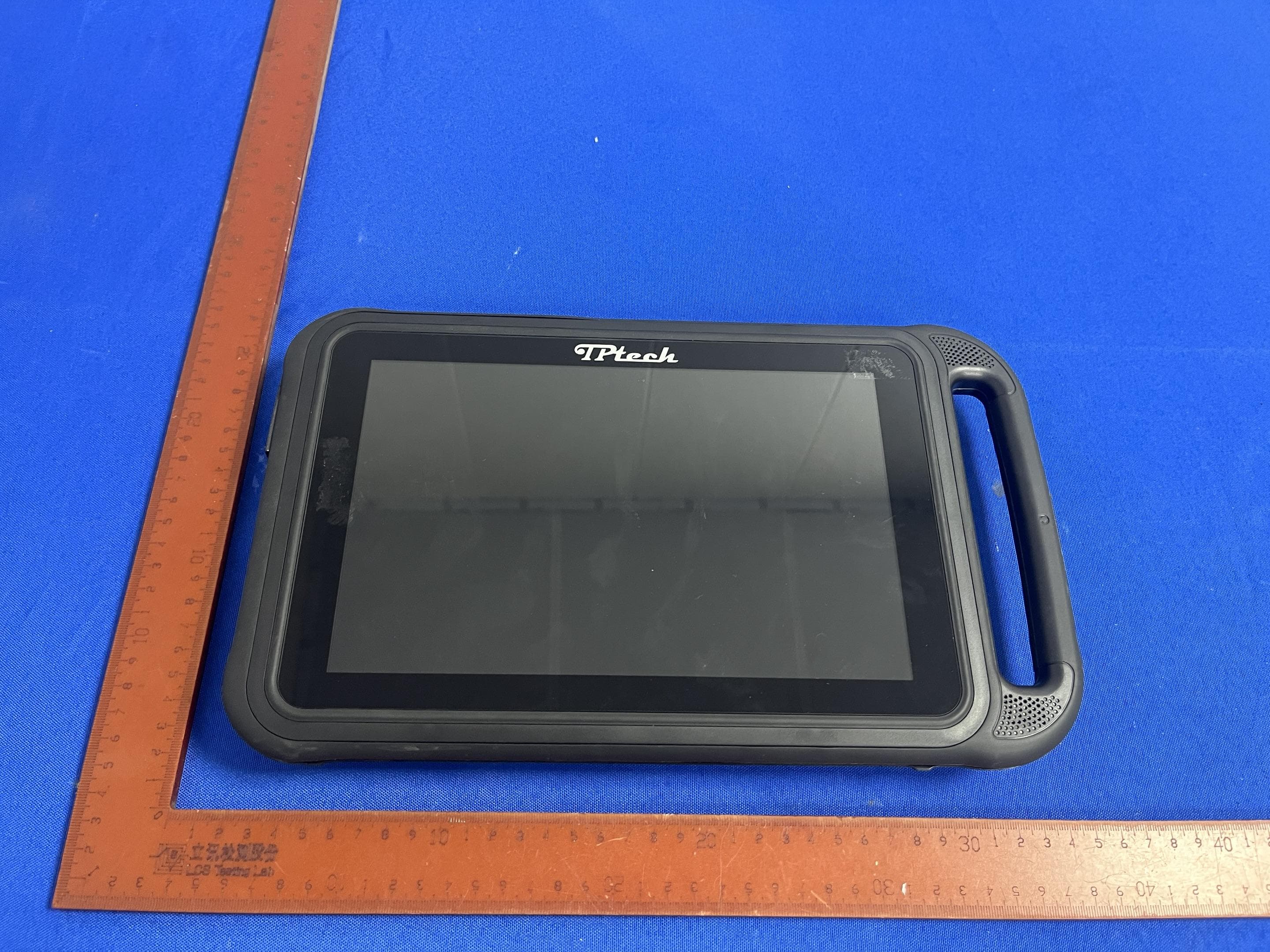
2ADZ7MGS101-05B7265
Sep 08, 2024Gaming tablet
Equipment Class
DTS - Digital Transmission System