2AE3OTXKILN-IKiln Data Transmitter
Fidemco, LLC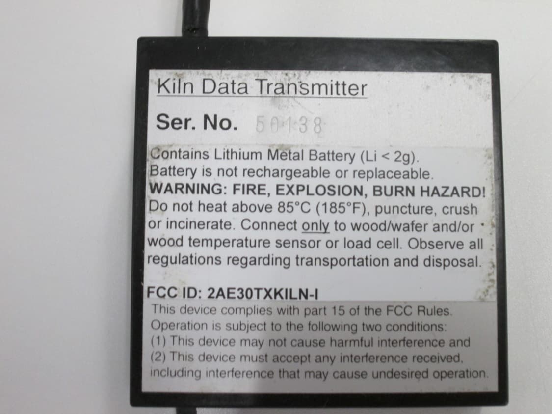
Click to zoom
Application Details
- Equipment Class
- DXX - Part 15 Low Power Communication Device Transmitter
- Date of Grant
- Nov 25, 2015
- Application Purpose
- Original Equipment
- Date of Application
- Nov 25, 2015
- Equipment Note
- Kiln Data Transmitter
- Frequency Range
- 916.50000000 - 916.50000000
- Company
- Fidemco, LLC
- Country
- United States
Documents & Files
Document Text
Text extracted from the exhibit documents filed with the FCC. Open a document above to read the original.
Users Manual
OPERATING INSTRUCTIONS FOR WIRELESS KILN DATA ACQUISITION SYSTEM consisting of Kiln Data Collectors and Kiln Data Transmitters INTRODUCTION These instructions are intended for professional manufacturers of • lumber drying equipment who use the Wireless Data Acquisition System as part of their kiln control system • monitoring equipment for wood moisture, temperature and relative humidity (RH) PRODUCT SUMMARY The Wireless Data Acquisition System features individual, battery-powered Kiln Data Transmitters, sending the readings they determine via radio frequencies to at least one Kiln Data Collector. The Kiln Data Collector picks up data from Kiln Data Transmitters and also determines dry bulb temperature readings and wet bulb temperature readings (both optional). Several models of Kiln Data Transmitters are available: a. Model MCT&RH-TX: Determining wood moisture content (MC) and relative humidity (RH) and temperature b. Model MCT-TX: Determining wood moisture content (MC) or equilibrium moisture content (EMC) and wood temperature (internal or external sensor) c. Model WT-TX: Determining wood temperature (external sensor) d. Model W-TX: Determining weight of a sample board on a scale equipped with a load cell All modules are encapsulated in a highly insulating epoxy compound with maximum hydrolytic stability protecting them against high ambient air humidity. The Kiln Data Collector and Kiln Data Transmitter models MCT-TX, WT-TX and W-TX can be installed in dry kilns; they have been designed to withstand the corrosive, hot air conditions existing there. They are specified for ambient temperatures of up to 85°C/185°F. The Kiln Data Transmitter MCT&RH-TX is specified for ambient temperatures of up to 70°C/160°F. 1 KILN DATA COLLECTOR INSTALLATION OF DATA COLLECTORS IN KILNS: Mount one Data Collector on one side of the lumber packs (front of kiln) and one on the other side (back of kiln). These are the best locations to make sure the signals of all transmitters are being picked up. Do not mount Data Collectors in the corners of the kiln. This is a bad place for radio frequency reception. Make sure no metal objects (like baffles) are shielding the Data Collectors from the transmitters in the kiln. Front Kiln Data Collector: This Data Collector can be mounted above the front door of the kiln, somewhere in the middle. Do not mount it above the level of the fan deck. Mount the Data Collector in such a way that the antenna is oriented vertically and not horizontally. Back Kiln Data Collector: Mount this Data Collector somewhere in the middle of the wall, in about the same elevation as the transmitters are placed in the lumber. Mount the Data Collector on a small metal plate and mount this plate with a 90-degree angle to the wall. The antenna is then oriented vertically and not horizontally. This gives better results than mounting the Collector flat on the wall. Follow instructions in separate document describing how to connect Kiln Data Collector. WARNING Note that the Data Collector does not detect incorrect readings if they are within the measuring range. Whenever false readings are suspected, the accuracy of the readings must be checked by taking comparative readings. To prevent secondary product damage caused by malfunction of the Data Collector, appropriate fail-safe functions must be incorporated into any control system using the readings delivered by the Data Collector. 2 KILN DATA TRANSMITTERS CONNECTIONS TO TRANSMITTERS (all models): WARNING: FIRE, EXPLOSION AND BURN HAZARD! Every transmitter contains one or two Lithium batteries which are not replaceable or rechargeable. Transmitters may ONLY be connected to the sensors / transducers that belong to the specific model, they MUST NOT be connected to anything else: a. Model MCT&RH-TX: Stainless steel banana plugs: Connect to wood or wafer in EMC-Station Circular 4-conductor connector (optional): Connect to wood temperature sensor 3.5mm Stereo jack: Connect to RH BluePeg sold by Lignomat b. Model MCT-TX: Stainless steel banana plugs: Connect to wood or wafer in EMC-Station Circular 4-conductor connector (optional): Connect to wood temperature sensor c. Model WT-TX: Circular 4-conductor connector: Connect to wood temperature sensor d. Model W-TX: 4-conductor cable without connector: Connect to load cell Follow instructions in separate document when connecting load cell. Only trained technicians should connect/remove a load cell to/from the transmitter. DO NOT connect the antenna to anything. SAFE OPERATING CONDITIONS FOR TRANSMITTERS (all models): WARNING: FIRE, EXPLOSION AND BURN HAZARD! Every transmitter contains one or two Lithium batteries which are not replaceable or rechargeable. DO NOT heat transmitters above limit specified on warning label 85°C/185°F or 70°C/158°F. DO NOT puncture, crush or incinerate transmitters. A lumber drying control system should limit the temperature in the kiln to a maximum of 85°C/185°F if transmitters are part of the lumber drying equipment. Make sure manual control of heat and spray will not lead to temperatures in excess of 85°C/185°F. 3 HANDLING OF MCT-TRANSMITTERS and WT-TRANSMITTERS: MCT-Transmitters (MCT-TX) and WT-Transmitters (WT-TX) have been designed for everyday use in a harsh kiln environment. However, damage (mechanical and to the circuitry) can occur if these guidelines are not followed to avoid conditions of abuse: Lithium Batteries can only take mechanical shocks to a certain degree. A free-fall of a transmitter on a hard surface can lead to internal short circuits of the battery. As a consequence the battery is drained and the transmitter will fail. When transmitters get stuck between the boards during the drying process in the kiln, they must not be freed by means of a hammer or the like for the same reason. It should be generally avoided to get the transmitters stuck between boards because this can also lead to excessive mechanical stress for the battery. When in doubt it’s better to have M…
Text truncated - open the document above for the full version.
Block Diagram
--- --------------------- 1' :Dij it-aLs --1 j,... f't-R.H ST L.. -Skb a,Y\{-e'YL'nQ (;a I -T I~C ,,fcts+-,'fYIode' X-wave-Lvt~~ ~ I.. ..( ~w k\Sot S er:a.L olo-fa. ~6) (:J. 00 .tel Kt' C-',O C0'Yl+-r-10 LLer I T I "Y'\...t-e..r"",,,,L o.sei Uo.t-oyo If M. fiz -'-----------;---... --- Co~f;JU"o.J.,o'r\ ot-ex.kr-mQL Se~br·s /it--~.s d-e...pe:rtc{s cDn Q.,f' pUc.oA"at), IJ..... tC-l"O- 1 .. C O"f'\+v-oLLer 1-",,-+.OSe-. tr){~ E x:-te-'Ntl:I-l h-oL .s '3'7\.oL Ls <5 ij'""-o.-ks . A"t\Q. Lo ~xte_V-"'lO-L.- LOCJ.-cl. ce-Ll A'rI-0.. L<r>~ }te-o...s CU'" 10I\!j C: I'C-fJ.,'fr.r VJood.../ T~er"m)-s+or Wa{ex G (\ f\ f:j ~ G) ~ >:, Hybn'rJ- CfJ 6' ,.5" KHz .~ SedC1-Ld.a.:fo_ II ITr-a'1'L.S 'rh.. ,'++e 'I' «Y\ 0 cJ-o. t;;) Z 4-00 ~(L \ !f{oetD..la...+-/ 6V1 _: OOk Z + t/ ): --1 ..).. --4 (i) > C/l < ~ =1 ' v,'
Cover Letter(s)
FIDEMCO ™ LLC ... moisture measurement you can trust! PO Box 20702 Portland, OR 97294 USA Phone: (503) 830-5517 Fax: (503) 255-1430 Email: [email protected] Federal Communications Commission 7435 Oakland Mills Road Columbia, MD 21046 To whom it may concern: This letter is to comply with Sections 0.457 and 0.459 pertaining to confidential material. Fidemco, LLC would like the following documents regarding this submission for FCC ID: 2AE3OTXKILN-I to be permanently kept confidential: 1. All pages of document “Internal Photos” 2. All pages of document “Schematics” The above material contains trade secrets or technical data, which are not publicly available and therefore guarded from competitors. Guarding is achieved by encapsulating the entire circuitry in an opaque epoxy potting material. Measurement technology and power management of this battery operated device are unique for this application and competitors have so far not been able to copy it. At this point in time there is no similar product on the market with any significant sales. Technical details of this product are only known in-house at Fidemco, LLC and to very few external suppliers. For these reasons we do not want the documents listed above to be accessible to the general public. Sincerely, Martin Glaeser / President
Cover Letter(s)
FIDEMCO ™ LLC ... moisture measurement you can trust! FCC Application Number: 0024677841 PO Box 20702 Grantee Code: 2AE30 Portland, OR 97294 USA Phone: (503) 830-5517 Fax: (503) 255-1430 Email: [email protected] Federal Communications Commission 7435 Oakland Mills Road Columbia, MD 21046 To whom it may concern: Several models are available of the device with the Equipment Product Code TXKILN-I. They differ in the type and configuration of external sensors/transducers that are connected to it. Sensors: 1. Wood or other natural materials: The device measures the electrical resistance between two electrodes connected to wood or other natural materials. 2. Thermistor: The device measures the electrical resistance of a thermistor. This sensor can either be installed internally or externally of the device. 3. Transducer for air temperature (T) and humidity (RH): The device reads digital data from an external transducer. This transducer is powered by the device and converts the signals generated by an integrated humidity and temperature sensor into serially transmitted digital data. 4. Load cell: The device measures the midpoint voltage of the Wheatstone Bridge contained in a load cell. Available models: a. Sensors 1, 2 and 3: Model MCT&RH-TX c. Sensors 1 and 2 only (sensor 2 installed internally or externally): Model MCT-TX b. Sensor 2 only (sensor 2 installed externally): Model WT-TX d. Transducer 4 only: Model W-TX Martin Glaeser President
External Photos
Annex 2 to Test Report # EMCC-150524BD Page 1 of 3 Issue Date: 2015-11-25 EMCCons DR. RAŠEK GmbH & Co. KG Moggast, Boelwiese 8 91320 Ebermannstadt Germany FCC Registration # 878769 Industry Canada Listing # 3464C 150524BD Telephone: +49 9194 9016 Telefax: +49 9194 8125 Mail: [email protected] Web: www.emcc.de Annex 2 to Test Report # EMCC-150524BD, 2015-11-25 EXTERNAL PHOTOGRAPHS OF EUT EQUIPMENT UNDER TEST: Device: MCT&RH-TX and W-TX Serial Number: 14037, 50138 FCC-ID: 2AE3OTXKILN-I Equipment Class: Telemetry Data Transmitter Manufacturer: Fidemco, LLC Address: PO Box 20702 Portland, OR 97294 USA Phone: +1 (503) 830-5517 Fax: +1 (503) 255-1430 RELEVANT STANDARD(S): 47 CFR § 15.249 MEASUREMENT PROCEDURE: ANSI C63.10-2013 RSS-Gen Issue 4 Other Annex 2 to Test Report # EMCC-150524BD Page 2 of 3 Issue Date: 2015-11-25 Test of MCT&RH-TX and W-TX (Fidemco, LLC) to 47 CFR § 15.249 © EMCCons DR. RAŠEK GmbH & Co. KG 2015 150524BD Photo A2-1: EUT “MCT&RH-TX” Photo A2-2: S/N of “MCT&RH-TX” Annex 2 to Test Report # EMCC-150524BD Page 3 of 3 Issue Date: 2015-11-25 Test of MCT&RH-TX and W-TX (Fidemco, LLC) to 47 CFR § 15.249 © EMCCons DR. RAŠEK GmbH & Co. KG 2015 150524BD Photo A2-3: EUT “W-TX” Photo A2-4: S/N of “W-TX”
Operational Description
Operational Description Kiln Data Transmitter Circuit functions: The Kiln Data Transmitter determines physical properties present in dry kilns for wood. Several models are available of the device. They differ in the type and configuration of external sensors/transducers that are connected to it via short cables. Sensors: #1. Wood or other natural materials: The device measures the electrical resistance between two electrodes connected to wood or other natural materials. #2. Thermistor: The device measures the electrical resistance of a thermistor. This sensor can either be installed internally or externally of the device. #3. Transducer for air temperature (T) and humidity (RH): The device reads digital data from an external transducer. This transducer is powered by the device and converts the signals generated by an integrated humidity and temperature sensor into serially transmitted digital data. #4. Load cell: The device measures the midpoint voltage of the Wheatstone Bridge contained in a load cell. Available models: a. Sensors #1 and #2 and transducer #3: Model MCT&RH-TX b. Sensors #1 and #2 only (sensor #2 installed internally or externally): Model MCT-TX c. Sensor #2 only (sensor #2 installed externally): Model WT-TX d. Transducer #4 only: Model W-TX Description of circuitry: The device is powered by one or two Lithium batteries. A voltage detector chip monitors the voltage level of the battery. Normally the microcontroller is in “Sleep”-mode (oscillator off) and doesn’t do anything. An internal wake-up feature of the microcontroller activates the device in constant time intervals. Approximately every 40sec the microcontroller controls the measuring circuitry and interprets the measuring signals to determine new readings. Approximately every 20sec the microcontroller sends the digital values serially to the hybrid transmitter chip at 2400Bd (6 bytes total). Every byte consists of 14 bits: Start and Stop bit, 8 data bits and 4 balance bits. Individually for every byte, the balance bits are determined by the microcontroller to achieve a duty cycle of 50%. In the worst case, when all data bits of all bytes are high, the duty cycle of the transmitter chip operated in on-off keyed modulation (OOK) will be less than 67%. Operating frequency of the transmitter chip is 916.5MHz at a typical peak output power of 0.54mW. A permanently attached ¼-wave length stub is used as antenna.
Test Report
Test Report # EMCC-1505248D Page 1 of71 lssue Date: 2015-11-25 TEST REPORT # EMCC- 1 50524B.D, 2015-11 -25 Th i s report repl aces Test Report # EM CC-1 505248 B, 201 5-09-09 EQUIPMENT UNDER TEST: Device: Serial Number: FCC-ID: Application: Manufacturer: Address: MCT&RH-TX and W-TX 14037,50138 2AE3OTXKILN-I Telemetry Data Transmitter Fidemco, LLC PO Box 20702 Portland, OR 97294 USA +1 (503) 830-5517 +1 (503) 255-1430 47 CFR S 15.249 fl nsS-Cen lssue 4 ! OÚrer Phone: Fax: RELEVANT STANDARD(S): MEASUREMENT PROCEDURE X nrusr c63.10-2013 TEST REPORT PREPARED BY: Patrick Reusch EMCCons DR. RASEK GmbH & Co. KG Moggast, Boelwiese 8 91320 Ebermannstadt Germany Phone: +49 9194 9016 Fax: +49 91948125 E-Mail: [email protected] TEST PERSONNEL: Patrick Reusch ng Döring L,A. n- +Á HEAD OF COMMERCIAL EMC AND RADIO DEPT.: EMCCons OR. RRSEX GmbH & Co KG Moggast, Boelwiese I 91 320 Ebermannstadt Germany FCC Registration # 878769 lndustry Canada Listing # 3464C 1 505248D EllC R.rC.o. S¿ht7 ¡nl ÊñnroôrcÊ'"al TestrrxJ DAKKS Telephone Telefax: Mail: Web: +49 9194 9016 +49 9194 8125 emc [email protected] www.emcc de 0eutsche Akkred¡tierun gsstelle D.Pr.-12067-01"00 Test Report # EMCC-150524BD Page 2 of 71 Issue Date: 2015-11-25 Test of MCT&RH-TX and W-TX (Fidemco, LLC) to 47 CFR § 15.249 © EMCCons DR. RAŠEK GmbH & Co. KG 2015 150524BD CONTENTS Page 1 General Information ................................................................................................................... 4 1.1 Purpose ........................................................................................................................................... 4 1.2 Limits and Reservations .................................................................................................................. 4 1.3 Test Location ................................................................................................................................... 4 1.4 Manufacturer ................................................................................................................................... 4 1.5 Dates and Test Location ................................................................................................................. 5 1.6 Ordering Information ....................................................................................................................... 5 1.7 Climatic Conditions ......................................................................................................................... 5 2 Product Description ................................................................................................................... 6 2.1 Equipment Under Test (EUT) ......................................................................................................... 6 2.2 Intended Use ................................................................................................................................... 7 2.3 EUT Peripherals/Simulators ............................................................................................................ 7 2.4 Mode of operation during testing and test set-up ........................................................................... 7 2.5 Modifications required for compliance ............................................................................................ 8 2.6 Duty-Cycle Correction ..................................................................................................................... 8 3 Test Results Summary .............................................................................................................. 9 4 Antenna Requirement .............................................................................................................. 10 4.1 Regulation ..................................................................................................................................... 10 4.2 Test Equipment ............................................................................................................................. 10 4.3 Test Procedures ............................................................................................................................ 10 4.4 Test Result .................................................................................................................................... 10 5 Occupied Bandwidth ............................................................................................................... 11 5.1 Regulation ..................................................................................................................................... 11 5.2 Test Equipment ............................................................................................................................. 11 5.3 Test Procedures ............................................................................................................................ 11 5.4 Test Result .................................................................................................................................... 13 5.5 Measurement Prescan-Plots ......................................................................................................... 14 6 Field Strength of Fundamental ............................................................................................... 16 6.1 Regulation ..................................................................................................................................... 16 6.2 Test Equipment ............................................................................................................................. 16 6.3 Test Procedures ............................................................................................................................ 17 6.4 Test Result .................................................................................................................................... 17 7 Band Edge C…
Text truncated - open the document above for the full version.
Test Setup Photos
Annex 1 to Test Report # EMCC-150524BD Page 1 of 4 Issue Date: 2015-11-25 EMCCons DR. RAŠEK GmbH & Co. KG Moggast, Boelwiese 8 91320 Ebermannstadt Germany FCC Registration # 878769 Industry Canada Listing # 3464C 150524BD Telephone: +49 9194 9016 Telefax: +49 9194 8125 Mail: [email protected] Web: www.emcc.de Annex 1 to Test Report # EMCC-150524BD, 2015-11-25 PHOTOGRAPHS OF TEST SET-UP EQUIPMENT UNDER TEST: Device: MCT&RH-TX and W-TX Serial Number: 14037, 50138 FCC-ID: 2AE3OTXKILN-I Equipment Class: Telemetry Data Transmitter Manufacturer: Fidemco, LLC Address: PO Box 20702 Portland, OR 97294 USA Phone: +1 (503) 830-5517 Fax: +1 (503) 255-1430 RELEVANT STANDARD(S): 47 CFR § 15.249 MEASUREMENT PROCEDURE: ANSI C63.10-2013 RSS-Gen Issue 4 Other Annex 1 to Test Report # EMCC-150524BD Page 2 of 4 Issue Date: 2015-11-25 Test of MCT&RH-TX and W-TX (Fidemco, LLC) to 47 CFR § 15.249 © EMCCons DR. RAŠEK GmbH & Co. KG 2015 150524BD Photo A1-1: Radiated emissions measurement at 3 m distance, 9 kHz – 30 MHz Photo A1-2: Radiated emissions measurement at 3 m distance, 30 MHz – 300 MHz Annex 1 to Test Report # EMCC-150524BD Page 3 of 4 Issue Date: 2015-11-25 Test of MCT&RH-TX and W-TX (Fidemco, LLC) to 47 CFR § 15.249 © EMCCons DR. RAŠEK GmbH & Co. KG 2015 150524BD Photo A1-3: Radiated emissions measurement at 3 m distance, 300 MHz – 1000 MHz Photo A1-4: Radiated emissions measurement at 3 m distance, 1 GHz – 6 GHz Annex 1 to Test Report # EMCC-150524BD Page 4 of 4 Issue Date: 2015-11-25 Test of MCT&RH-TX and W-TX (Fidemco, LLC) to 47 CFR § 15.249 © EMCCons DR. RAŠEK GmbH & Co. KG 2015 150524BD Photo A1-5: Radiated emissions measurement at 1.5 m distance, 6 GHz – 10 GHz
Contact Information
Applicant
Martin Glaeser(President)
Test Firm
EMCCons DR. RASEK GmbH & Co. KGReinhard Sauerchell
Technical Specifications
| # | Rule Parts | Frequency Range | Power Output |
|---|---|---|---|
| 1 | 15C | 916.5 MHz - 916.5 MHz | - |