2AE5E2AE5E-FR10IBPower interrupter for fire mitigation on electric appliance
Marsco Technologies Inc.
Click to zoom
Application Details
- Equipment Class
- DXT - Part 15 Low Power Transceiver, Rx Verified
- Date of Grant
- Aug 25, 2015
- Application Purpose
- Original Equipment
- Date of Application
- Jul 08, 2015
- Equipment Note
- Power interrupter for fire mitigation on electric appliance
- Frequency Range
- 434.11700000 - 434.11700000
- Company
- Marsco Technologies Inc.
- Country
- Canada
Documents & Files
Document Text
Text extracted from the exhibit documents filed with the FCC. Open a document above to read the original.
Users Manual
Marsco Technologies Inc. TM 1 FireRanger Operations Manual System Components: 1. Battery powered Keypad controller with wireless transceiver 2. 220Vac Range Interbox power controller with wireless transceiver 3. Battery powered Smoke Sensor with wireless transceiver Basic functionality of the system: The function of this product is to disconnect the power to an electric range in the event that smoke is detected by it's dedicated smoke sensor. It is neither a primary nor secondary function to issue an alarm. The audible 'chirp' from the equipment serves only as a simple troubleshooting aid to help the user understand why the electric range has been shut off. Marsco Technologies Inc. TM 2 This product does not interact with any other existing smoke detectors and does not operate as a smoke detector/alarm. It's dedicated 'Smoke Sensor' serves only to send an electronic signal to the 'Interbox' to shut off the stove. There is no smoke alarm functionality associated with this product. This product is not an emergency signaling or smoke alarm product. All components of the FireRanger system must be operational (powered) and within RF transceiver functional range (typically within 8m). The recommended placement of the Smoke Sensor is minimum12 inches from any ceiling or wall corner. Example: Minimum12 inches out from the wall, or 12 inches down from the ceiling. Installing Batteries To install batteries in the Keypad controller, remove the back panel by removing 4 Philips head screws securing the back panel of the Keypad controller. Install two (2) “AAA” batteries observing the correct polarity. Replace the back panel. Marsco Technologies Inc. TM 3 To install the battery in the Smoke Sensor, open the battery access door on the side of the smoke sensor. Insert a fully charged 9 volt battery. Close the access door. No batteries are required for the Interbox controller to operate, rather it is only necessary to plug the Interbox controller into a 240Vac Range power outlet. The current version of firmware (v1.7) requires that the Interbox and Smoke Sensor wireless transceivers be operating and in “ready” state before initiating the keypad as will be described in the proceeding: Marsco Technologies Inc. TM 4 Turning on the Keypad Press the button. The button will illuminate Red. The Keypad has successfully been brought from its low current “sleep” mode”. If the default NO PASSWORD option is active, the Interbox controller will be armed (activated) at this time. The Green LED in the upper left hand corner of the Keypad will illuminate briefly, followed by the button’s Red LED extinguishing. Please note that the button is also referred to as the Panic Button on page 10. A password can be added to prevent unauthorized operation of the electric range. If a PASSWORD is desired, proceed to enter the PASSWORD as follows: Marsco Technologies Inc. TM 5 Keypad Operation Password: The default factory password is 0000, which in effect is a NO PASSWORD condition. Step 1: To enter a password for added security, it is necessary to press and release the * and # in successive order. When the * is pressed the button LED will illuminate indicating successful recognition by the operating firmware. When the # is pressed the button LED will extinguish. The Red LED in the upper left corner of the keypad will illuminate. The keypad has now been successfully placed in PASSWORD CHANGE mode. Step 2: Enter the new desired numeric password consisting of any 4 numeric button presses (0000 is reserved as a no password entry). Marsco Technologies Inc. TM 6 Step 3: Re-enter the 4 numbers selected as the password. The Red LED in the upper left corner of the Keypad will flash four times, indicating a successful password entry. To exit the PASSWORD CHANGE mode at any time, press the * once and the password will return to what was originally entered. Note: if the Red LED illuminates at any point while re-entering the 4-number password in Step 3, the password has been entered incorrectly or a problem with the password entry has been encountered. The control firmware will return to the beginning of Step 2 (indicated by the Red LED extinguishing). Perform Steps 2 and 3 until the four flashes are observed as described in Step 3. Marsco Technologies Inc. TM 7 If you are attempting to change the password and this error occurs, the password will revert back to the original password. In the event you decide to not proceed with Step 2, press the * once to exit the PASSWORD CHANGE mode. The password will return to what was originally entered. Turning off the system To turn off the FireRanger system it is necessary to re-enter the current password. If the default NO PASSWORD is being used, it is only necessary to press the “0” button once to turn off the FireRanger system. This will disable the Interbox 240Vac power controller and place the Keypad in the low power 'sleep' mode. Note: In the current configuration the Smoke Sensor will continue to issue HEART BEAT messages (see page 8 for the HEART BEAT description). Marsco Technologies Inc. TM 8 HEART BEAT operation After the Interbox has successfully activated the Keypad controller will issue a HEART BEAT RF transmission approximately every 10 minutes. The HEART BEAT indicator is a short Green LED flash in the upper left corner of the Keypad. The Smoke Sensor will also issue a HEART BEAT RF transmission approximately every 10 minutes, repeating continuously as long as battery power has been applied to that device. This HEART BEAT is intended to maintain the RF link between the Keypad-Interbox-Smoke Sensor system. The HEART BEAT from each issuing device (Keypad or Smoke Sensor) is received by the Interbox RF transceiver, maintaining the 240Vac power controller in an active state. The Interbox transceiver will respond to each issuing device with an acknowledgment RF transmission. If the Interbox transceiver does not receive a HEART BEAT from either of the issuing devices, the 240Vac power controlle…
Text truncated - open the document above for the full version.
Block Diagram
CC1110 MCU/TxRx 26MHz Crystal Planar Antenna Filter Network AC-DC PSU 240AC IN 12VDC OUT Load Control Relays Relay Drive and Fail-Safe 3.3v Regulator FR1.0IB Block Diagram 433MHz 433MHz
External Photos
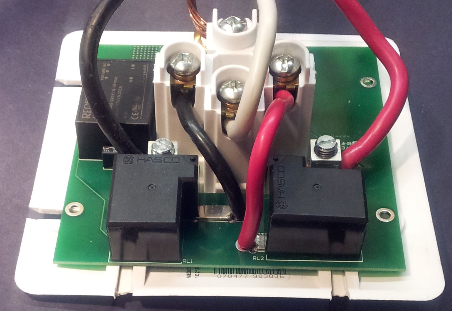
Prepared by: LabTest Certification Inc. Client: Marsco Technologies Inc. Date Issued: June 02, 2015 Report No.: 12731-2E Project No: 12731 Revision No.: 0 Page 33 of 42 This document shall not be reproduced or utilized in any form or by any means, except in full, without the written approval of LabTest Certification Inc. DCN: 1034, Rev 4 APPENDIX B: EUT photos - EUT: Top View Hot Line #2 Hot Line #1
ID Label/Location Info
FireRanger InterBox External View 3”x1.5” Label affixed on side of enclosure, UL Listed ribbon and ink
Operational Description
FR1.0IB InterBox Module (IB) Operational Description The FR1.0IB InterBox (abbreviation for 'Interconnection Box') connects directly to an AC wall receptacle and has its own receptacle which switches the power to a connected electric appliance. It communicates via RF to two other parts of the system, a keypad and a smoke sensor. If the Interbox receives an alarm signal from the smoke sensor, or a panic signal from the keypad, it disconnects power to the electric appliance. It self-tests the RF connection regularly to improve safety. An 'all clear' signal from the keypad will cause the Interbox to reconnect power to the electric appliance if there is no longer an alarm signal being received from the smoke sensor.
Schematics
11 22 33 44 D D C C B B A A Drawn By:Checked Title: QAApprovedClient Rev. Williamson Technical Services 12896 Hwy 215 Rines C reek NS Canada Sheet: Revision History Rev Description Date By Drawing Number: Size Scale: N/A A williamson ts Initial Prototype BC 10Jul09 V1 Expand program header BC 17Au09 V2 Add C1, Chg C6,7,8 to UL App. BC 5Dec09 B Chg Power Relays and Drv BC 12May10 C Chg U2, Del R3,4 BC 29May10 D Swap Pin 7,9 at U3, add D2, C7, Del X2 BC 16Jun10 E Add D7,8,Q4, move Buzzer IO BC 26Jun10 F Del D7,8,Q4 BC 2Jul10 G CHG R2 TO IND BC 6Aug10 H CHG R14 TO 680 BC 22May11 J CHG RLY, PSU, SCRW TERM BC 29Jul13 K Bill Crandall 10Jul2009 C3.7 Marsco Technologies M PCB,SCH,FR1, INTERBOX 240v Domestic Wiring All circuitry housed within 240v electrical box +12V Range Receptacle P1_2 1 DVDD 2 P1_1 3 P1_0 4 P0_0 5 P0_1 6 P0_2 7 P0_3 8 P0_4 9 DVDD 10 P0_5 11 P0_6 12 P0_7 13 P2_0 14 P2_1 SDA 15 P2_2 SCLK 16 P2_3-XSOC32_Q1 17 P2_4-XOSC32_Q2 18 AVDD 19 XOSC_Q2 20 XOSC_Q1 21 AVDD 22 RF_P 23 RF_N 24 AVDD 25 AVDD 26 RBIAS 27 GUARD 28 AVDD_DREG 29 DCOUPL 30 RESET_N 31 P1_7 32 P1_6 33 P1_5 34 P1_4 35 P1_3 36 Pad 37 U3 L2 27n L327n C16220p C20 3.9p C213.9p L522n C228.2p L427n C18220p C235.6p VddVdd Vdd Vdd Vdd Q3 + C194.7u X1 26MHz 3.3v Reg RLABuzzer CS SCK SI SO LED2LED3 +12V RST_P LED3LED2 2 1 R71K 2 1 R81K For development only +12V ANT 1 GND 2 GND 3 GND 4 GND 5 GND 6 ANT1 Antenna Black White Red Vdd K A LED1 K A LED2 K A LED3 CSSCKSISORST_PVdd Program Header SDASCLK SCLK SDA 123456789 J2 RLB HI ON PULSED ON RY Det RY Det R62.2K C647U IN 1 GND 2 EN 3 NC 4 OUT 5 U2 For development only +12V +VDC OUT 2 -VDC OUT 3 ACL 5 ACN 6 PS1PSU Q1Q2 J4SHUNT J6SHUNT J3 SHUNT J7 SHUNT J5SCREW J1 SCREW 1234 5 RL2 1234 5 RL1 C241n C4 0.1u L1Bead C10.1u C947u C10 1u C30.1u R11 2.7k R5 56k C15 220p C17220pC50.1u C20.1u C13 27p C14 27p R14100 R13100 R333k R1033kR1210k R9100 D1 12 BZ1 D5 D7 D6 C7 0.1u Vdd CHG F1 TO FUSE RESISTOR BC 27Mar2014 L F1330 ADD R1 AT Q2 BC 21Aug2014 M R156k C2.7RevJ _PCB1 +12V 1 of 1
Test Report
TEST REPORT For Marsco Technologies Inc. 23 Carmichael Court Halifax, Nova scotia B3T 1T1, Canada Date: June 02, 2015 Report No.: 12731-2E Revision No.: 0 Project No.: 12731 Equipment: Fire Ranger System Model No.: FR1.0-IB ONE STOP GLOBAL CERTIFICATION SOLUTIONS 3133-20800 Westminster Hwy, Richmond, BC V6V 2W3, Canada Phone: 604-247-0444 Fax: 604-247-0442 www.labtestcert.com Prepared by: LabTest Certification Inc. Client: Marsco Technologies Inc. Date Issued: June 02, 2015 Report No.: 12731-2E Project No: 12731 Revision No.: 0 Page 2 of 42 This document shall not be reproduced or utilized in any form or by any means, except in full, without the written approval of LabTest Certification Inc. DCN: 1034, Rev 4 TABLE OF CONTENTS TEST REPORT ................................................................................................................................................ 3 General product information: ............................................................................................................................ 4 Frequencies ...................................................................................................................................................... 5 List of ancillary and/or support equipment provided by the applicant .............................................................. 5 Description of Interface Cables for Testing ...................................................................................................... 5 Software and Firmware .................................................................................................................................... 5 Worst-case configuration and mode of operation during testing ...................................................................... 5 Modifications Required for Compliance............................................................................................................ 5 Test Equipment Verified for function ................................................................................................................ 5 Measurement Uncertainty ................................................................................................................................ 6 Markings ........................................................................................................................................................... 6 Test Summary .................................................................................................................................................. 7 AC Power Line Conducted Emission ............................................................................................................... 8 Test Limits ..................................................................................................................................................... 8 Test Setup ..................................................................................................................................................... 8 Setup Block Diagram .................................................................................................................................... 9 Test Result .................................................................................................................................................. 10 Summary of the operation of RF Transmission .............................................................................................. 14 Test Limits ................................................................................................................................................... 14 Reviewed Results: ...................................................................................................................................... 14 Field Strength of Fundamental – Intentional Radiator .................................................................................... 17 Test Limits ................................................................................................................................................... 17 Test Setup ................................................................................................................................................... 18 Setup Block Diagram .................................................................................................................................. 18 Test Setup in Chamber ............................................................................................................................... 18 Test Results: ............................................................................................................................................... 19 Field Strength of Spurious Emissions ............................................................................................................ 20 Test Limits ................................................................................................................................................... 20 Test Setup ................................................................................................................................................... 21 Test Results: ............................................................................................................................................... 21 Radiated Emission; Intentional Radiators ...................................................................................................... 25 Test Limits ................................................................................................................................................... 25 Test Setup ................................................................................................................................................... 26 Test Results: ......................................................................................................................…
Text truncated - open the document above for the full version.
Test Setup Photos
Prepared by: LabTest Certification Inc. Client: Marsco Technologies Inc. Date Issued: June 02, 2015 Report No.: 12731-2E Project No: 12731 Revision No.: 0 Page 34 of 42 This document shall not be reproduced or utilized in any form or by any means, except in full, without the written approval of LabTest Certification Inc. DCN: 1034, Rev 4 APPENDIX C: Test setup photos - Test configuration for Field Strength measurement Prepared by: LabTest Certification Inc. Client: Marsco Technologies Inc. Date Issued: June 02, 2015 Report No.: 12731-2E Project No: 12731 Revision No.: 0 Page 35 of 42 This document shall not be reproduced or utilized in any form or by any means, except in full, without the written approval of LabTest Certification Inc. DCN: 1034, Rev 4 - Test configuration for Harmonic measurement, over 1GHz Prepared by: LabTest Certification Inc. Client: Marsco Technologies Inc. Date Issued: June 02, 2015 Report No.: 12731-2E Project No: 12731 Revision No.: 0 Page 36 of 42 This document shall not be reproduced or utilized in any form or by any means, except in full, without the written approval of LabTest Certification Inc. DCN: 1034, Rev 4 - Test configuration for Unintentional measurement below 30MHz
Contact Information
Applicant
Marvin Butt(Mr)
Technical Contact
Williamson TechnicalBill Harry Crandall
[email protected]9028054190
12896 Hwy 215 · Rines Creek, NS · Canada
Non-Technical Contact
Marsco TechnologiesScott Kelly
[email protected]604-834-0739
Test Firm
LabTest Certification Inc.Kavinder Dhillon
Technical Specifications
| # | Rule Parts | Frequency Range | Power Output |
|---|---|---|---|
| 1 | 15C | 434.117 MHz - 434.117 MHz | - |
Other Applications from Marsco Technologies Inc.

2AE5E2AE5E-FR10SS
Oct 29, 2015Sensor for Power Interrupter for fire mitigation on appliance
Equipment Class
DXT - Part 15 Low Power Transceiver, Rx Verified
2AE5E2AE5E-FR10KB
Oct 28, 2015Control for power interrupter for fire mitigation on appliance
Equipment Class
DXT - Part 15 Low Power Transceiver, Rx Verified