2AE5K1400708OneTap Transmitter
Danco, Inc.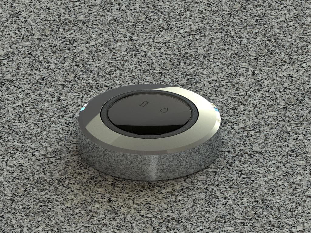
Click to zoom
Application Details
- Equipment Class
- DSC - Part 15 Security/Remote Control Transmitter
- Date of Grant
- Nov 18, 2015
- Application Purpose
- Original Equipment
- Date of Application
- Nov 15, 2015
- Equipment Note
- OneTap Transmitter
- Frequency Range
- 433.92000000 - 433.92000000
- Company
- Danco, Inc.
- Country
- United States
Documents & Files
Document Text
Text extracted from the exhibit documents filed with the FCC. Open a document above to read the original.
Users Manual
OneTap title page goes here Table of Contents To be inserted here NSF trademark? Filter model 1 Tested and Certified by NSF International against NSF/ANSI Standard Filter model 2 & 3 Tested and Certified by NSF International against NSF/ANSI Standard 42 for the reduction of Chlorine Tatse and Odor and particulate Class 1 and Standard 53 for the reduction of Lead, Cyst, Turbidity, Asbestos, mercury, Lindane, Atrazine, Toxaphene and 2,4-D. WQA trademark? Important Safety Information Warning: Read the entire manual before attempting to install or use the filter system. Failure to follow the guides outlined below could result in damage to the filter system, personal property, or personal injury. Note: Check with local codes and follow their guidelines for installing plumbing fixtures. Use the filtration system only on potable, safe to drink cold water line only (100F max). Warning: The OneTap water filter is intended to remove some suspended particles, odor and taste contaminates from other-wise safe to drink water. It is not intended to remove microbiological contaminates. To reduce risk of property damage due to water leakage, install the filter system where it will not be exposed to temperatures below freezing. The filter unit should be installed indoors. The recommended operating temperature is 40ᵒF – 104ᵒF (5ᵒC - 40ᵒC). The water filter system has been designed to withstand water pressures up to 120 psi. However if your water supply is 100 psi or more, it is suggested that you install a pressure reducing valve in line with the cold water supply before the filter unit. Discard any leftover packaging materials according to local laws and ordinances. About the Filters Your OneTap water filtration system ships with 3 filter canisters. Need more info here 1) Sediment Filter – 5 micron filter that mounts in the first position. Reduces particles from entering the filter system and your everyday water usage. 2) ... Filter – Carbon based filter that reduces... and mounts in the second position. 3) ... Filter – Carbon based filter that reduces... and mounts in the third position. Installation To install the filter unit, first decide where it will be mounted. A typical installation will have the filter unit mounted on the right hand side of the cabinet (side closest to the cold water supply). 1) Using the template provided install 2 screws into the cabinet wall. 2) The screws should be tightened to the point that they leave 3/16 inch clearance. 3) Install 6 AA batteries into the filter unit. a. Remove the battery pack from the front of the unit. b. Pay close attention to the orientation of the batteries as you slide them into place. c. Replace the populated battery pack d. Upon successful battery installation, you should hear a single chirp, followed by 2x flash of lights on the front of the unit, then a double chirp followed by another 2x flash of lights. This is the proper power up sequence. If the unit fails to power up correctly, remove the battery pack and double check the battery installation. Be sure to dispose of the spent batteries in accordance with your local codes and guidelines. 4) Install 1 CR2032 3V coin cell battery into the sender unit (positive on top). a. Use a #1 Philip’s screw-driver to open the battery cover. b. The fresh battery should be placed into the receptacle with the positive side up. c. Replace the battery cover and screw. d. Test by pushing the activation button. If successful the blue water glass icon should light up for about 1 second. 5) Hang the filter unit on the 2 screws in the cabinet side wall. 6) Turn OFF the water supply to the faucet. 7) Remove the supply line from the cold water supply. 8) Attach the green adapter fitting to the cold water supply. 9) Attach the blue adapter fitting to the faucet supply line. 10) Determine the amount of green tubing necessary to reach the cold water supply. Make sure to leave enough excess that the line is able to droop at a relaxed loop. 11) Trim the excess tubing using the cutters provided. Tip: cut the tubing at one of the ¾ inch indicator markings. 12) Insert the green tubing into the green adapter. Make sure the 1 st indicator mark goes past the adapter opening. 13) Follow the same procedure for the blue tubing using the faucet supply line adapter. 14) Install the 3 filters that came with the system. To install a filter, line up the key-way and insert the canister. Twist clock-wise about ¼ turn until you notice a positive click. a. Position 1 Sediment Filter b. Position 2 ?? Carbon Filter c. Position 3 ?? Carbon Filter 15) Slowly turn on the water supply and observe for leaks. 16) Slowly turn on faucet cold water and observe for leaks. 17) With the water running fully on, press and release the sender unit switch. The water flow in the faucet should drop noticeably. There may be bursts of pressure as the filters fill with water and the air in the system is purged. 18) If the water flow goes back to full, press and release the sender unit switch again. Sometimes the air will cause the filter system to switch off as the air is purged. Repeat as necessary. 19) Your filter system is now installed. Fresh filtered water is just a button press away. Using Your Water Filter 1) Turn on the faucet cold water. 2) Press and release the sender unit button. 3) Notice the change in water flow from the faucet. 4) Fill container with filtered water. 5) Turn off faucet, filter unit resets automatically. Indicator lights and Sounds Your water filter comes with state of the art monitoring technology. The electronics within the filter system periodically check the battery voltage, and keep track of actual filter usage. If a condition exists that requires the user’s attention, a notification alarm will sound along with an indicator light to help diagnose the issue. The indicator lights can be found on the front of the unit. Light definitions Top LED – Sender Unit battery needs to be replaced (CR2032) Middle LED – Filter Unit batteries need…
Text truncated - open the document above for the full version.
Cover Letter(s)
166 South Carter Street, Genoa City, WI 53128 Request for Confidentiality Date: November 5, 2015 FCC Authorization & Evaluation Division 7435 Oakland Mills Road Columbia, Maryland 21046 RE: Certification Application FCC ID: 2AE5K1400708 Pursuant to 47 CFR Section 0.459 Danco, Inc. understands that requests for non disclosure and confidential treatment is being made for the following information as stated under the Code of Federal Regulations Chapter 47, Part 0.459: Block Diagram Schematics Operational Description The above materials contain trade secrets, proprietary and technical information that would customarily be guarded from competitors under 47 CFR section 0.457(d)(2). Disclosure or publication of any portion of this company confidential material to other parties could cause substantial competitive harm and provide unjustified benefits for competitors. Danco, Inc. understands that pursuant to 47 CFR section 0.457(d)(1)(ii) disclosure of the applicant and all accompanying documentation will not be made before the date of the grant. Thank you for your attention to this matter. Signatory William M. Stumpf OATS Manager D.L.S. Electronic Systems, Inc.
Cover Letter(s)
166 South Carter Street, Genoa City, WI 53128 Letter of Agency Date: November 5, 2015 FCC Authorization & Evaluation Division 7435 Oakland Mills Road Columbia, Maryland 21046 To Whom It May Concern: Please be advised that Danco, Inc. authorizes D.L.S. Electronic Systems, Inc. to act on their behalf, until otherwise notified, for applications submitted to American Certification Body, Inc. (ACB). We certify that we are not subject to denial of federal benefits, that includes FCC benefits, pursuant to Section 5301 of the Anti-Drug Abuse ACT of 1988, U.S.C. 862. Further, no party, as defined in 47 CFR 1.2002(b), to the application is subject to denial of federal benefits, that includes FCC benefits. Thank you for your attention to this matter. Signatory, William M. Stumpf OATS Manager D.L.S. Electronic Systems, Inc. 166 South Carter Street, Genoa City, WI 53128 FCC Labeling Requirements and Information Date: November 5, 2015 FCC Authorization & Evaluation Division 7435 Oakland Mills Road Columbia, Maryland 21046 RE: FCC Labeling Requirements FCC ID: SAE5K1400708 The following label information is required by the FCC Rules and Regulations for certified devices. Thank you for your attention to these matters. Sincerely, William M. Stumpf OATS Manager D.L.S. Electronic Systems, Inc. 166 South Carter Street, Genoa City, WI 53128 Modification Letter Date: November 5, 2015 FCC Authorization & Evaluation Division 7435 Oakland Mills Road Columbia, Maryland 21046 RE: Certification Application FCC ID: SAE5K1400708 Please be advised that the following information is a list of modifications that will be included in the production process for the above-referenced equipment. Change 1: There were no modifications made during testing. Change 2: Change 3: Change 4: Thank you for your attention to this matter. Signatory William M. Stumpf OATS Manager D.L.S. Electronic Systems, Inc.
External Photos
External Photos Company: Danco, Inc. Model: OneTap, #1400708 FCC ID: 2AE5K1400708 Top Side - Plastic Enclosure (Please note that the blue & white squares are just light reflections) Bottom Side Assembly View
Internal Photos
Internal Photos of Test Sample Company: Danco, Inc. Model: OneTap, #1400708 FCC ID: 2AE5K1400708 Circuit Board – Side 1 Circuit Board – Side 2
Test Report
166 South Carter, Genoa City, WI 53128 Page 1 of 21 Company: Danco, Inc. Model Tested: 1400708 Report Number: 21072 Project Number: 7126 i. Cover Page Code of Federal Regulations 47 Part 15 – Radio Frequency Devices Subpart C – Intentional Radiators Section 15.231 Periodic operation in the band 40.66 - 40.70 MHz and above 70 MHz THE FOLLOWING MEETS THE ABOVE TEST SPECIFICATION Formal Name: OneTap Kind of Equipment: Standalone battery operated transmitter for water filtration system Frequency Range: 433.92 MHz Test Configuration: Battery operated transmitter tested for intentional radiated emissions in three orthogonal planes. Model Number(s): 1400708 Model(s) Tested: 1400708 Serial Number(s): none (Test Sample) Date of Tests: June 16, 2015 Test Conducted For: Danco, Inc. 501 Earl Road Shorewood, IL 60404, USA NOTICE: “This test report relates only to the items tested and must not be used by the client to claim product endorsement by NVLAP or any agency of the U.S. Government”. Please see the "Description of Test Sample" page listed inside of this report. © Copyright 1983 - 2015 D.L.S. Electronic Systems, Inc. COPYRIGHT NOTICE This report must not be reproduced (except in full), without the approval of D.L.S. Electronic Systems, Inc. 166 South Carter, Genoa City, WI 53128 Page 2 of 21 Company: Danco, Inc. Model Tested: 1400708 Report Number: 21072 Project Number: 7126 ii. Signature Page SIGNATURE PAGE Tested By: Paul Leo Test Engineer Reviewed By: William Stumpf OATS Manager Approved By: Brian Mattson General Manager 166 South Carter, Genoa City, WI 53128 Page 3 of 21 Company: Danco, Inc. Model Tested: 1400708 Report Number: 21072 Project Number: 7126 iii. Table of Contents Table of Contents i. Cover Page .......................................................................................................................................1 ii. Signature Page .................................................................................................................................2 iii. Table of Contents .............................................................................................................................3 iv. NVLAP Certificate of Accreditation ...............................................................................................4 1.0 Summary of Test Report ..................................................................................................................5 2.0 Introduction ......................................................................................................................................5 3.0 Test Facilities ...................................................................................................................................5 4.0 Description of Test Sample ..............................................................................................................6 5.0 Test Equipment ................................................................................................................................7 6.0 Test Arrangements ...........................................................................................................................7 7.0 Test Conditions ................................................................................................................................8 8.0 Modifications Made To EUT For Compliance ................................................................................8 9.0 Additional Descriptions ...................................................................................................................8 10.0 Results ..............................................................................................................................................8 11.0 Conclusion .......................................................................................................................................8 Appendix A – Test Photos ...........................................................................................................................9 Appendix B – Measurement Data ..............................................................................................................12 B1.0 Emission Bandwidth – 20 dB ................................................................................................... 12 B2.0 Automatic Deactivation ............................................................................................................ 14 B3.0 Field Strength of Emissions – Fundamental and Spurious ....................................................... 16 B4.0 Duty Cycle Correction .............................................................................................................. 19 166 South Carter, Genoa City, WI 53128 Page 4 of 21 Company: Danco, Inc. Model Tested: 1400708 Report Number: 21072 Project Number: 7126 iv. NVLAP Certificate of Accreditation 166 South Carter, Genoa City, WI 53128 Page 5 of 21 Company: Danco, Inc. Model Tested: 1400708 Report Number: 21072 Project Number: 7126 1.0 Summary of Test Report It was determined that the Danco, Inc. OneTap, Model 1400708, complies with the requirements of CFR 47 Part 15 Subpart C Section 15.231. Subpart C Section 15.231 Applicable Technical Requirements Tested: Section Description Procedure Note Compliant? 15.231(c) 20 dB Emission Bandwidth ANSI C63.4-2014 & ANSI C63.10-2013 1,2 Yes 15.231(a)(1) Automatic Deactivation ANSI C63.4-2014 & ANSI C63.10-2013 1,2 Yes 15.231(b) (and 15.205) Field Strength of Emissions - Fundamental and Spurious - ANSI C63.4-2014 & ANSI C63.10-2013 1,2 Yes 15.35(c) Duty Cycle ANSI C63.4-2014 & ANSI C63.10-2013 1,2 Yes Note 1: Tested in 3 orthogonal planes. Note 2: Radiated emission measurement. 2.0 Introduction On June 16, 2015 the OneTap, Model 1400708, as provided from Danco, Inc. was tested to the requirements of CFR 47 Part 15 Subpart C Section 15.231. To meet these requirements, the procedures contained within this repo…
Text truncated - open the document above for the full version.
Test Setup Photos
Test Setup Photos FCC ID: 2AE5K1400708 Photo Information and Test Setup: Item: Danco, Inc. OneTap Transmitter, Model 1400708 Radiated Emissions – ‘X’ Position Radiated Emissions – ‘Y’ Position Radiated Emissions – ‘Z’ Position Radiated Emissions – Above 1000 MHz – Front Radiated Emissions – Above 1000 MHz – Back
Contact Information
Applicant
Jeff Siegrist(Sr. Electrical Engineer)
Technical Contact
D.L.S. Electronic Systems, IncWilliam (Bill) Martin Stumpf
[email protected]262-279-0210
166 South Carter Street · Genoa City · United States
Test Firm
DLS Electronic Systems, Inc.William Stumpf
Technical Specifications
| # | Rule Parts | Frequency Range | Power Output |
|---|---|---|---|
| 1 | 15.231 | 433.92 MHz - 433.92 MHz | - |