Text extracted from the exhibit documents filed with the FCC. Open a document above to read the original.
GE Transportation Systems RF Gear Case Sensor 6/3/15 Installation Instructions Rev. A1 Author: David Petersen Approval: Sethu Madhavan 84A234272AB Issued: GET Engineering, 6/21/13 BUS. AREA: Loco Sheet 1 of 31 This Drawing is the Property of GENERAL ELECTRIC COMPANY, TRANSPORTATION SYSTEMS DIVISION. This drawing is loaned upon the express condition that it shall not be reproduced in any manner, and shall be returned upon demand. It is submitted for evaluation purposes and it, and the information contained therein, shall not be otherwise used nor disclosed to third parties without written permission of General Electric Co. DHMS Installation and Programming Instructions Revision History Revision Date DSRVW Author Description of Revision A NA D. Petersen Added FCC , programming, troubleshooting updates. Table of Contents 1.0 INTRODUCTION ........................................................................................................................................... 2 2.0 SENSOR INSTALLATION............................................................................................................................ 6 3.0 SENSOR REMOVAL (When Applicable) ..................................................................................................... 9 4.0 GATEWAY INSTALLATION AND WIRING ........................................................................................... 10 5.0 SENSOR PROGRAMMING & VALIDATION .......................................................................................... 15 6.0 READING OIL LEVELS DURING LOCOMOTIVE MAINTENANCE CYCLES ................................... 16 7.0 UPDATING SENSOR & GATEWAY FIRMWARE ................................................................................... 17 8.0 TROUBLESHOOTING ................................................................................................................................ 24 9.0 DATA LOG DOWNLOAD .......................................................................................................................... 29 APPENDIX A: LOADING DHMS SOFTWARE ON A PC .................................................................................... 30 APPENDIX B: SOFTWARE VERSION CONTROL AND MANAGEMENT ....................................................... 31 GE Transportation Systems RF Gear Case Sensor 6/3/15 Installation Instructions Rev. A1 Author: David Petersen Approval: Sethu Madhavan 84A234272AB Issued: GET Engineering, 6/21/13 BUS. AREA: Loco Sheet 2 of 31 This Drawing is the Property of GENERAL ELECTRIC COMPANY, TRANSPORTATION SYSTEMS DIVISION. This drawing is loaned upon the express condition that it shall not be reproduced in any manner, and shall be returned upon demand. It is submitted for evaluation purposes and it, and the information contained therein, shall not be otherwise used nor disclosed to third parties without written permission of General Electric Co. 1.0 INTRODUCTION This document outlines the steps required to install, remove, and program the RF Gear Case Sensor (RGS) and gateway onto a locomotive. These sensors and gateway are designed to collect and transmit gear case oil data while in line-haul service. Follow all shop safety rules when working on or under the locomotive. FCC Compliance and Notification GE Part Numbers: 84A237140P1, DHMS Gateway 84A234628P1, RGS Sensor FCC ID: new number (Pending approval) These devices comply with part 15 of the FCC Rules. Operation is subject to the following two conditions: (1) These devices may not cause harmful interference, and (2) these devices must accept any interference received, including interference that may cause undesired operation. Changes or modifications to the DHMS Gateway or Sensor are prohibited. Any changes made to these devises without the written approval by GE Engineering could void the user's authority to operate this equipment. Per RSS-Gen, Section 8.4, this device complies with Industry Canada license-exempt RSS standards. Operation is subject to the following two conditions: (1) this device may not cause interference, and (2) this device must accept any interference, including interference that may cause undesired operation of the device -------------------------------------------------------------------------- Par RSS-Gen, la section 8.4, cet appareil est conforme aux normes Industrie Canada RSS exemptes de licence. Son fonctionnement est soumis aux deux conditions suivantes: (1) ce dispositif ne peut pas provoquer d'interférences et (2) cet appareil doit accepter toute interférence, y compris les interférences qui peuvent causer un mauvais fonctionnement de l'appareil. Les modifications apportées à la passerelle DHMS ou le capteur sont interdits. Les modifications apportées à ces dispositifs sans l'approbation écrite par GE Ingénierie pourraient annuler l'autorité de l'utilisateur à utiliser cet équipement. 1.1 Acronyms BS Battery Switch DHMS Drive Train Health Monitoring System FCC US Federal Communications Commission GE General Electrical MBS Maintenance Battery Switch RGS RF Gear Case Sensor GE Transportation Systems RF Gear Case Sensor 6/3/15 Installation Instructions Rev. A1 Author: David Petersen Approval: Sethu Madhavan 84A234272AB Issued: GET Engineering, 6/21/13 BUS. AREA: Loco Sheet 3 of 31 This Drawing is the Property of GENERAL ELECTRIC COMPANY, TRANSPORTATION SYSTEMS DIVISION. This drawing is loaned upon the express condition that it shall not be reproduced in any manner, and shall be returned upon demand. It is submitted for evaluation purposes and it, and the information contained therein, shall not be otherwise used nor disclosed to third parties without written permission of General Electric Co. RSS Canadian Radio Standards Specification GE Transportation Systems RF Gear Case Sensor 6/3/15 Installation Instructions Rev. A1 Author: David Petersen Approval: Sethu Madhavan 84A234272AB Issued: GET Engineering, 6/21/13 BUS. AREA: Loco Sheet 4 of 31 This Drawing is the Proper…
Text truncated - open the document above for the full version.
This confidential document is the property of DarCEO, Inc. and shall not be reproduced, distributed or used without the express written consent of DarCEO, Inc. June 15, 2015 Federal Communications Commission Authorization and Evaluation Division 7435 Oakland Mills Road Columbia, Maryland 21046 To whom it may concern, We hereby respectfully request that under the provision of 47 CFR 0.459 and 0.457(d), the documents listed below and attached with this application for certification be provided with confidential status. • Schematics.pdf • Operational Description.pdf • Frequency Block Diagrams.pdf Any exhibit / information for which we have requested confidentiality, but which may not be accorded such treatment by the FCC, should be returned to us. The documents listed above contain trade secrets that are treated as confidential by us. Substantial competitive harm to us could result should they be made available to the public. FCC ID Number: 2AE6484A234628 Functional Description: The sensor takes capacitance, temperature, accelerometer, etc. data readings periodically and communicates them to the gateway if it is in range. An operator can also get in close proximity to the sensor and trigger readings from it with a handheld RFID unit. The units are designed to go on locomotives. RFID in the sensor is passive. Sincerely, Brian T. Hemmelman Principal Engineer, DarCEO Inc.
This confidential document is the property of DarCEO, Inc. and shall not be reproduced, distributed or used without the express written consent of DarCEO, Inc. May 20, 2015 Federal Communications Commission Authorization and Evaluation Division 7435 Oakland Mills Road Columbia, Maryland 21046 Subject: Oil Sensor External Photos Image 1: Casing – Back Side Page 2 of 8 2 of 8 This confidential document is the property of DarCEO, Inc. and shall not be reproduced, distributed or used without the express written consent of DarCEO, Inc. Image 2: Casing – Bottom Side Page 3 of 8 3 of 8 This confidential document is the property of DarCEO, Inc. and shall not be reproduced, distributed or used without the express written consent of DarCEO, Inc. Image 3: Casing – Front Side Page 4 of 8 4 of 8 This confidential document is the property of DarCEO, Inc. and shall not be reproduced, distributed or used without the express written consent of DarCEO, Inc. Image 4: Casing – Left Side Page 5 of 8 5 of 8 This confidential document is the property of DarCEO, Inc. and shall not be reproduced, distributed or used without the express written consent of DarCEO, Inc. Image 5: Casing – Top Side Page 6 of 8 6 of 8 This confidential document is the property of DarCEO, Inc. and shall not be reproduced, distributed or used without the express written consent of DarCEO, Inc. Image 6: Casing – Right Side Page 7 of 8 7 of 8 This confidential document is the property of DarCEO, Inc. and shall not be reproduced, distributed or used without the express written consent of DarCEO, Inc. Image 7: Casing – Back Side, View 2 Page 8 of 8 8 of 8 This confidential document is the property of DarCEO, Inc. and shall not be reproduced, distributed or used without the express written consent of DarCEO, Inc. Image 8: Casing – Front Side, View 2 Part Number: 84A234628P1 Functional Description: The sensor takes capacitance, temperature, accelerometer, etc. data readings periodically and communicates them to the gateway if it is in range. An operator can also get in close proximity to the sensor and trigger readings from it with a handheld RFID unit. The units are designed to go on locomotives. RFID in the sensor is passive. Sincerely, Brian T. Hemmelman, Principal Engineer, DarCEO Inc.
This confidential document is the property of DarCEO, Inc. and shall not be reproduced, distributed or used without the express written consent of DarCEO, Inc. July 1, 2015 Federal Communications Commission Authorization and Evaluation Division 7435 Oakland Mills Road Columbia, Maryland 21046 Subject: Oil Sensor FCC Label and Location FCC ID Number: 2AE6484A234628 Figure 1: FCC Label Location The FCC label will comply with the FCC regulations per 2.925, 2.926(d), and 2.1033(b)(7). Functional Description: The sensor takes capacitance, temperature, accelerometer, etc. data readings periodically and communicates them to the gateway if it is in range. An operator can also get in close Page 2 of 2 2 of 2 This confidential document is the property of DarCEO, Inc. and shall not be reproduced, distributed or used without the express written consent of DarCEO, Inc. proximity to the sensor and trigger readings from it with a handheld RFID unit. The units are designed to go on locomotives. RFID in the sensor is passive. Sincerely, Brian T. Hemmelman Principal Engineer, DarCEO Inc.
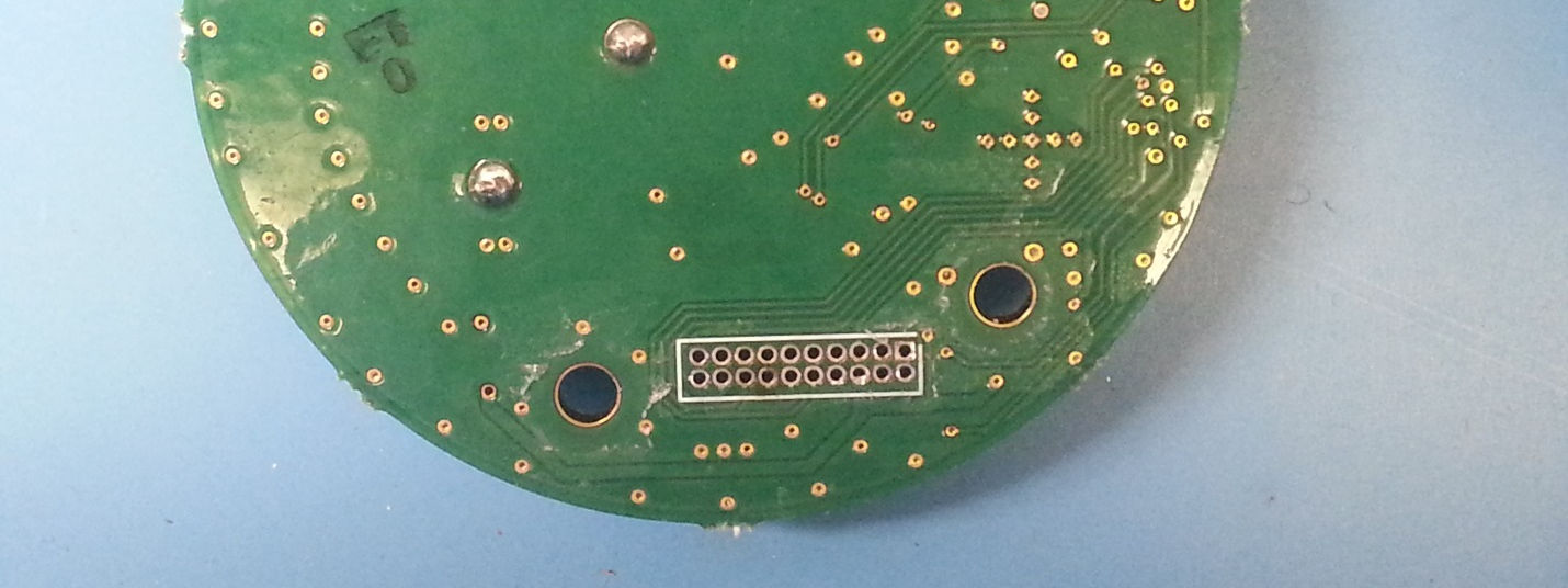
This confidential document is the property of DarCEO, Inc. and shall not be reproduced, distributed or used without the express written consent of DarCEO, Inc. June 15, 2015 Federal Communications Commission Authorization and Evaluation Division 7435 Oakland Mills Road Columbia, Maryland 21046 Subject: Oil Sensor Internal Photos Image 1: Antenna Board Assembly, Solder Side Page 2 of 4 2 of 4 This confidential document is the property of DarCEO, Inc. and shall not be reproduced, distributed or used without the express written consent of DarCEO, Inc. Image 2: Antenna Board Assembly, Component Side Page 3 of 4 3 of 4 This confidential document is the property of DarCEO, Inc. and shall not be reproduced, distributed or used without the express written consent of DarCEO, Inc. Image 3: Battery Board Assembly, Solder Side Page 4 of 4 4 of 4 This confidential document is the property of DarCEO, Inc. and shall not be reproduced, distributed or used without the express written consent of DarCEO, Inc. Image 4: Battery Board Assembly, Component Side Part Number: 84A234628G1 Functional Description: The sensor takes capacitance, temperature, accelerometer, etc. data readings periodically and communicates them to the gateway if it is in range. An operator can also get in close proximity to the sensor and trigger readings from it with a handheld RFID unit. The units are designed to go on locomotives. RFID in the sensor is passive. Sincerely, Brian T. Hemmelman Principal Engineer, DarCEO Inc.
This confidential document is the property of DarCEO, Inc. and shall not be reproduced, distributed or used without the express written consent of DarCEO, Inc. May 20, 2015 Federal Communications Commission Authorization and Evaluation Division 7435 Oakland Mills Road Columbia, Maryland 21046 Subject: Oil Sensor Antenna Documentation The GE Draintrain Health Monitoring System (DHMS) Oil Sensor uses a Taoglas SMD Patch Antenna for its 802.15.4 radio. The specifications of this antenna are: 1 Range of Receiving Frequency: 2400 MHz to 2500 MHz 2 Bandwidth: 100 MHz @ -7dB 3 Polarization: Linear 4 VSWR: 3.0 max @ Center Frequency 5 Peak Gain: +2 dBi typ. 6 Impedance: 50 Ohms 7 Dimensions: 12mm x 12mm x 4mm 8 Operating Temperature: -40°C to +85°C 9 Storage Temperature: -40°C to +85°C 10 Termination: Ag (Environmentally Friendly Pb Free) 11 Manufacturer Part Number: SWLP.2450.12.4.B.02 As this a permanently attached surface mount antenna it is in compliance with FCC rule 15.203. Page 2 of 3 2 of 3 This confidential document is the property of DarCEO, Inc. and shall not be reproduced, distributed or used without the express written consent of DarCEO, Inc. Figure 1: Mechanical drawing of SWLP.2450.12.4.B.02 from datasheet. Figure 2: Stock images of SWLP.2450.12.4.B.02 from datasheet. Page 3 of 3 3 of 3 This confidential document is the property of DarCEO, Inc. and shall not be reproduced, distributed or used without the express written consent of DarCEO, Inc. Figure 3: Image of antenna mounted on Oil Sensor PCB Part Number: 84A234628P1 Functional Description: The sensor takes capacitance, temperature, accelerometer, etc. data readings periodically and communicates them to the gateway if it is in range. An operator can also get in close proximity to the sensor and trigger readings from it with a handheld RFID unit. The units are designed to go on locomotives. RFID in the sensor is passive. Sincerely, Brian T. Hemmelman Principal Engineer, DarCEO Inc.
This report must not be used to claim product certification, approval, or endorsement by NVLAP, NIST, or any agency of the federal government of the United States of America. This Report may only be duplicated in its entirety DarCEO Inc. Drivetrain Health Monitoring System- Sensor FCC 2.1091:2015 Report # DARC0001 NVLAP Lab Code: 201049-0 CERTIFICATE OF EVALUATION 2014-12-10 Product compliance is the responsibility of the client; therefore, the tests and equipment modes of operation represented in this report were agreed upon by the client, prior to testing. The results of this test pertain only to the sample(s) tested. The specific description is noted in each of the individual sections of the test report supporting this certificate of test. Last Date of Test: May 7, 2015 DarCEO Inc. Model: Drivetrain Health Monitoring System- Sensor Radio Equipment Testing Standards Specification Method FCC 2.1091:2015 KDB 447498 D01 General RF Exposure Guidance v05r02 Results Method Clause Test Description Applied Results Comments 7.1 Maximum Permissible Exposure Yes Pass Deviations From Test Standards None Approved By: Don Facteau, IT Manager Report No. DARC00012/9 REVISION HISTORY REV 2014.10.14 Revision Number Description Date Page Number 00 None Report No. DARC00013/9 ACCREDITATIONS AND AUTHORIZATIONS REV 2015.2.19 United States FCC - Designated by the FCC as a Telecommunications Certification Body (TCB). Certification chambers, Open Area Test Sites, and conducted measurement facilities are listed with the FCC. A2LA - Accredited by A2LA to ISO / IEC 17065 as a product certifier. This allows Northwest EMC to certify transmitters to FCC and IC specifications. NVLAP - Each laboratory is accredited by NVLAP to ISO 17025 Canada IC - Recognized by Industry Canada as a Certification Body (CB). Certification chambers and Open Area Test Sites are filed with IC. European Union European Commission – Validated by the European Commission as a Conformity Assessment Body (CAB) under the EMC directive and as a Notified Body under the R&TTE Directive. Australia/New Zealand ACMA - Recognized by ACMA as a CAB for the acceptance of test data. Korea MSIP / RRA - Recognized by KCC’s RRA as a CAB for the acceptance of test data. Japan VCCI - Associate Member of the VCCI. Conducted and radiated measurement facilities are registered. Taiwan BSMI – Recognized by BSMI as a CAB for the acceptance of test data. NCC - Recognized by NCC as a CAB for the acceptance of test data. Singapore IDA – Recognized by IDA as a CAB for the acceptance of test data. Israel MOC – Recognized by MOC as a CAB for the acceptance of test data. Hong Kong OFCA – Recognized by OFCA as a CAB for the acceptance of test data. Vietnam MIC – Recognized by MIC as a CAB for the acceptance of test data. SCOPE For details on the Scopes of our Accreditations, please visit: http://www.nwemc.com/accreditations/ http://gsi.nist.gov/global/docs/cabs/designations.html Report No. DARC00014/9 FACILITIES REV 2015.2.19 California Labs OC01-13 41 Tesla Irvine, CA 92618 (949) 861-8918 Minnesota Labs MN01-08, MN10 9349 W Broadway Ave. Brooklyn Park, MN 55445 (612)-638-5136 New York Labs NY01-04 4939 Jordan Rd. Elbridge, NY 13060 (315) 554-8214 Oregon Labs EV01-12 22975 NW Evergreen Pkwy Hillsboro, OR 97124 (503) 844-4066 Texas Labs TX01-09 3801 E Plano Pkwy Plano, TX 75074 (469) 304-5255 Washington Labs NC01-05 19201 120 th Ave NE Bothell, WA 9801 (425)984-6600 NVLAP NVLAP Lab Code: 200676-0 NVLAP Lab Code: 200881-0 NVLAP Lab Code: 200761-0 NVLAP Lab Code: 200630-0 NVLAP Lab Code:201049-0 NVLAP Lab Code: 200629-0 Industry Canada 2834B-1, 2834B-3 2834E-1 N/A 2834D-1, 2834D-2 2834G-1 2834F-1 BSMI SL2-IN-E-1154R SL2-IN-E-1152R N/A SL2-IN-E-1017 SL2-IN-E-1158R SL2-IN-E-1153R VCCI A-0029 A-0109 N/A A-0108 A-0201 A-0110 Recognized Phase I CAB for ACMA, BSMI, IDA, KCC/RRA, MIC, MOC, NCC, OFCA US0158 US0175 N/A US0017 US0191 US0157 Report No. DARC00015/9 PRODUCT DESCRIPTION 2014-12-10 Client and Equipment Under Test (EUT) Information Company Name: DarCEO Inc. Address: 1675 Samco Road City, State, Zip: Rapid City, SD 57702 Test Requested By: Brian Hemmelman Model: Drivetrain Health Monitoring System - Sensor Evaluation Date: May 7, 2015 Information Provided by the Party Requesting the Test Functional Description of the EUT: The Sensor takes capacitance, temperature, accelerometer, etc. data readings periodically and communicates them to the Gateway via a 2.4 GHz DTS radio. Testing Objective: To demonstrate compliance with FCC requirements for RF exposure for 2.1091 mobile devices. Report No. DARC00016/9 MAXIMUM PERMISSIBLE EXPOSURE (MPE) WTD.2014.12.17 OVERVIEW Human exposure to RF emissions from mobile devices (47 CFR §2.1091) may be evaluated based on the MPE limits adopted by the FCC for electric and magnetic field strength and/or power density, as appropriate, since exposures are assumed to occur at distances of 20 cm or more from persons. ANSI C95.1:2005 + Amd 1:2010 specifies a minimum separation distance of 20 cm for performing reliable field measurements to determine adherence to MPE limits. If the minimum separation distance between a transmitter and nearby persons is more than 20 cm under normal operating conditions, compliance with MPE limits may be determined at such distance from the transmitter. When applicable, operation instructions and prominent warning labels may be used to alert the exposed persons to maintain a specified distance from the transmitter or to limit their exposure durations and usage conditions to ensure compliance. If the use of warning labels on a transmitter is not effective or desirable, the alternative of performing SAR evaluation with the device at its closest range to persons under normal operating conditions may be used. The field strength and power density limits adopted by the FCC are based on whole-body averaged exposure and the assumption of RF field levels relate most accurately to estimating whole-body averaged SAR. This means some lo…
Text truncated - open the document above for the full version.
This report must not be used to claim product certification, approval, or endorsement by NVLAP, NIST, or any agency of the federal government of the United States of America. This Report may only be duplicated in its entirety DarCEO Inc. Drivetrain Health Monitoring System- Sensor FCC 15.207:2015 FCC 15.247:2015 Report # DARC0001.2 NVLAP Lab Code: 201049-0 CERTIFICATE OF TEST 2014-12-10 Product compliance is the responsibility of the client; therefore, the tests and equipment modes of operation represented in this report were agreed upon by the client, prior to testing. The results of this test pertain only to the sample(s) tested. The specific description is noted in each of the individual sections of the test report supporting this certificate of test. Last Date of Test: April 24, 2015 DarCEO Inc. Model: Drivetrain Health Monitoring System- Sensor Radio Equipment Testing Standards Specification Method FCC 15.207:2015 ANSI C63.10:2009 FCC 15.247:2015 ANSI C63.10:2009 Results Method Clause Test Description Applied Results Comments 6.2 Powerline Conducted Emissions No N/A Not required for a battery powered EUT. 6.5, 6.6 Spurious Radiated Emissions Yes Pass 6.7 Band Edge Compliance Yes Pass 6.7 Spurious Conducted Emissions Yes Pass Radiated Method 6.9.1 Occupied Bandwidth Yes Pass 6.10.2 Output Power Yes Pass 6.11.2 Power Spectral Density Yes Pass 7.5 Duty Cycle Yes Pass Deviations From Test Standards None Approved By: Jeremiah Darden, Operations Manager Report No. DARC0001.22/33 REVISION HISTORY REV 2014.10.14 Revision Number Description Date Page Number 00 None Report No. DARC0001.23/33 ACCREDITATIONS AND AUTHORIZATIONS REV 2015.2.19 United States FCC - Designated by the FCC as a Telecommunications Certification Body (TCB). Certification chambers, Open Area Test Sites, and conducted measurement facilities are listed with the FCC. A2LA - Accredited by A2LA to ISO / IEC 17065 as a product certifier. This allows Northwest EMC to certify transmitters to FCC and IC specifications. NVLAP - Each laboratory is accredited by NVLAP to ISO 17025 Canada IC - Recognized by Industry Canada as a Certification Body (CB). Certification chambers and Open Area Test Sites are filed with IC. European Union European Commission – Validated by the European Commission as a Conformity Assessment Body (CAB) under the EMC directive and as a Notified Body under the R&TTE Directive. Australia/New Zealand ACMA - Recognized by ACMA as a CAB for the acceptance of test data. Korea MSIP / RRA - Recognized by KCC’s RRA as a CAB for the acceptance of test data. Japan VCCI - Associate Member of the VCCI. Conducted and radiated measurement facilities are registered. Taiwan BSMI – Recognized by BSMI as a CAB for the acceptance of test data. NCC - Recognized by NCC as a CAB for the acceptance of test data. Singapore IDA – Recognized by IDA as a CAB for the acceptance of test data. Israel MOC – Recognized by MOC as a CAB for the acceptance of test data. Hong Kong OFCA – Recognized by OFCA as a CAB for the acceptance of test data. Vietnam MIC – Recognized by MIC as a CAB for the acceptance of test data. SCOPE For details on the Scopes of our Accreditations, please visit: http://www.nwemc.com/accreditations/ http://gsi.nist.gov/global/docs/cabs/designations.html Report No. DARC0001.24/33 MEASUREMENT UNCERTAINTY TMU.2014.12.03 Measurement Uncertainty When a measurement is made, the result will be different from the true or theoretically correct value. The difference is the result of tolerances in the measurement system that cannot be completely eliminated. To the extent that technology allows us, it has been our aim to minimize this error. Measurement uncertainty is a statistical expression of measurement error qualified by a probability distribution. A measurement uncertainty estimation has been performed for each test per our internal quality document WP 342. The estimation is used to compare the measured result with its "true" or theoretically correct value. The expanded measurement uncertainty (K=2) for each test is on each data sheet. Our measurement data meets or exceeds the measurement uncertainty requirements of the applicable specification; therefore, the test data can be compared directly to the specification limit to determine compliance. The calculations for estimating measurement uncertainty are based upon ETSI TR 100 028 (or CISPR 16-4-2 as applicable), and are available upon request. The following table represents the Measurement Uncertainty (MU) budgets for each of the tests that may be contained in this report. Test + MU - MU Frequency Accuracy (Hz) 0.0007% -0.0007% Amplitude Accuracy (dB) 1.2 dB -1.2 dB Conducted Power (dB) 0.3 dB -0.3 dB Radiated Power via Substitution (dB) 0.7 dB -0.7 dB Temperature (degrees C) 0.7°C -0.7°C Humidity (% RH) 2.5% RH -2.5% RH Voltage (AC) 1.0% -1.0% Voltage (DC) 0.7% -0.7% Field Strength (dB) 4.7 dB -4.7 dB AC Powerline Conducted Emissions (dB) 2.9 dB -2.9 dB Report No. DARC0001.25/33 FACILITIES REV 2015.2.19 California Labs OC01-13 41 Tesla Irvine, CA 92618 (949) 861-8918 Minnesota Labs MN01-08, MN10 9349 W Broadway Ave. Brooklyn Park, MN 55445 (612)-638-5136 New York Labs NY01-04 4939 Jordan Rd. Elbridge, NY 13060 (315) 554-8214 Oregon Labs EV01-12 22975 NW Evergreen Pkwy Hillsboro, OR 97124 (503) 844-4066 Texas Labs TX01-09 3801 E Plano Pkwy Plano, TX 75074 (469) 304-5255 Washington Labs NC01-05 19201 120 th Ave NE Bothell, WA 9801 (425)984-6600 NVLAP NVLAP Lab Code: 200676-0 NVLAP Lab Code: 200881-0 NVLAP Lab Code: 200761-0 NVLAP Lab Code: 200630-0 NVLAP Lab Code:201049-0 NVLAP Lab Code: 200629-0 Industry Canada 2834B-1, 2834B-3 2834E-1 N/A 2834D-1, 2834D-2 2834G-1 2834F-1 BSMI SL2-IN-E-1154R SL2-IN-E-1152R N/A SL2-IN-E-1017 SL2-IN-E-1158R SL2-IN-E-1153R VCCI A-0029 A-0109 N/A A-0108 A-0201 A-0110 Recognized Phase I CAB for ACMA, BSMI, IDA, KCC/RRA, MIC, MOC, NCC, OFCA US0158 US0175 N/A US0017 US0191 US0157 Report No. DARC0001.26/33 PRODUCT DESCRIPTION 2014-12-10 Client and Equ…
Text truncated - open the document above for the full version.
SPURIOUS RADIATED EMISSIONS WTD.2015.03.10 PSA-ESCI 2015.03.03, EmiR5 2015.03.19.1 SPURIOUS RADIATED EMISSIONS WTD.2015.03.10 PSA-ESCI 2015.03.03, EmiR5 2015.03.19.1 SPURIOUS RADIATED EMISSIONS WTD.2015.03.10 PSA-ESCI 2015.03.03, EmiR5 2015.03.19.1 XMit 2015.01.14 Transmit lab test.JPG BAND EDGE COMPLIANCE XMit 2015.01.14 Transmit lab test.JPG OCCUPIED BANDWIDTH XMit 2015.01.14 Output Power (1).JPG Output Power (2).JPG OUTPUT POWER XMit 2015.01.14 Output Power (3).JPG Output Power (4).JPG OUTPUT POWER XMit 2015.01.14 Output Power (5).JPG Output Power (6).JPG OUTPUT POWER XMit 2015.01.14 Transmit lab test.JPG POWER SPECTRAL DENSITY XMit 2015.01.14 Duty Cycle (1).JPG Duty Cycle (2).JPG DUTY CYCLE OUT OF BAND EMISSIONS XMit 2014.02.07 NORTHWEST OUT OF BAND EMISSIONS NweTx 2014.11.06 EMC EUT Horizontal (1).JPG EUT Horizontal (2).JPG OUT OF BAND EMISSIONS
| # | Rule Parts | Frequency Range | Power Output |
|---|---|---|---|
| 1 | 15C | 2.42 GHz - 2.48 GHz | 6.20 mW |

Gateway
Equipment Class
DTS - Digital Transmission System