2AE6Q30810356RF remote control
L'Image Home Products Inc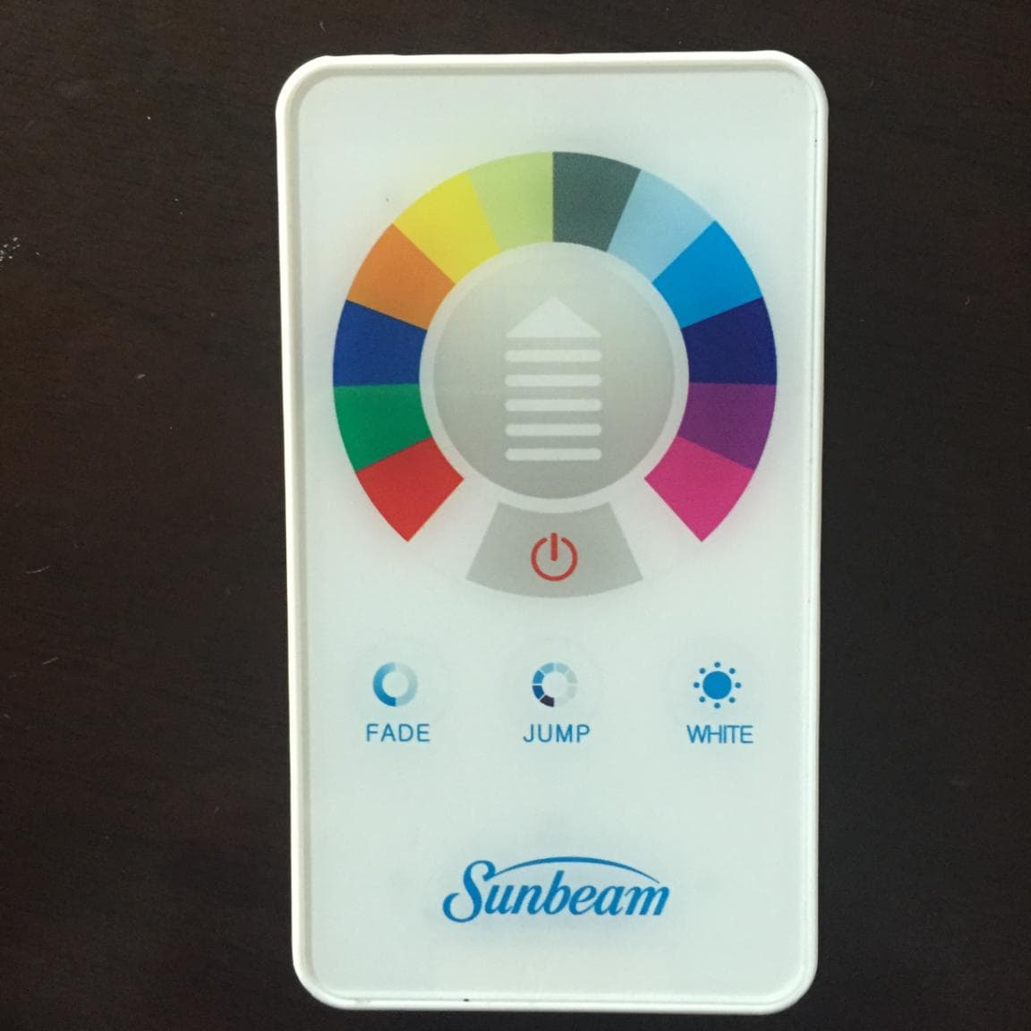
Click to zoom
Application Details
- Equipment Class
- DXX - Part 15 Low Power Communication Device Transmitter
- Date of Grant
- Aug 26, 2015
- Application Purpose
- Original Equipment
- Date of Application
- Aug 25, 2015
- Equipment Note
- RF remote control
- Frequency Range
- 2434.00000000 - 2434.00000000
- Company
- L'Image Home Products Inc
- Country
- Canada
Documents & Files
Document Text
Text extracted from the exhibit documents filed with the FCC. Open a document above to read the original.
Users Manual
USER MANUAL FOR RGBW PUCK LIGHT KIT Please read the instructions before assembling and using your new LED puck light kit. NOTICE: FOR INDOOR AND DRY LOCATION USE ONLY. ADHENSIVE TAPE MAY DAMAGE SURFACE WHEN REMOVE IT. PARTS: Puck light 3pcs controller 1pc INSTALLATION Before installation, make sure the surface you intend to install is free of moisture, oil, grease, dust and dirt to ensure proper adhesive. Careful, the adhesive tape may damage the painted surface when removing. STEP 1 Install the puck light. Mark the target place where you want to install. Remove one side of the tape and stick to the LED puck light. Then remove the other side of the tape and stick to the place you want to install. Remove one side of the double sided tape and secure to the sensor. STEP 2 Us the same way to install the controller. STEP 3 Connect the plug in adapter connector to the puck light. Then connect the adapter to the adaptor connector by inserting the jack on the adapter. STEP 4 Plug the AC/DC adapter into the power supply, the LED puck light is ready to work. STEP 5 Control the puck light by remote control. CAUTION To reduce the risk of fire, electric shock or injury to persons: 1) Use only insulated staples or plastics ties to secure cords 2) Route and secure cords so that they will not be pinched or damaged when the cabinet is pushed to wall; 3) Position the portable cabinet light with respect to the cabinet so the lamp replacement marking are able to be read during re-lamping; 4) Not intended for recessed installation in ceiling, or soffits; and 5) The National Electrical Code (NEC) does not permit cords to be concealed where damage to insulation may go unnoticed. To prevent fire danger, do not run cords behind walls, ceiling, soffits, or cabinets where it may be inaccessible for examination. Cords should be visually examined periodically and immediately replaced when any damage is noted. This device complies with Part 15 of the FCC Rules. Operation is subject to the following two conditions: (1) this device may not cause harmful interference, and (2) this device must accept any interference received, including interference that may cause undesired operation. Warning: Changes or modifications to this unit not expressly approved by the party responsible for compliance could void the user's authority to operate the equipment. NOTE: This equipment has been tested and found to comply with the limits for a Class B digital device, pursuant to Part 15 of the FCC Rules. These limits are designed to provide reasonable protection against harmful interference in a residential installation. This equipment generates, uses and can radiate radio frequency energy and, if not installed and used in accordance with the instructions, may cause harmful interference to radio communications. However, there is no guarantee that interference will not occur in a particular installation. If this equipment does cause harmful interference to radio or television reception, which can be determined by turning the equipment off and on, the user is encouraged to try to correct the interference by one or more of the following measures: - Reorient or relocate the receiving antenna. - Increase the separation between the equipment and receiver. - Connect the equipment into an outlet on a circuit different from that to which the receiver is connected. - Consult the dealer or an experienced radio/ TV technician for help.
Cover Letter(s)
Subject: Confidentiality Request for: FCC ID:2AE6Q30810356, IC ID:20347-30810356 Request for Confidentiality Date: ____20150610____ Subject: Confidentiality Request for: FCC ID:2AE6Q30810356, IC ID:20347-30810356 Pursuant to FCC 47 CRF 0.457(d) and 0.459 and IC RSP-100, Section 10, the applicant requests that a part of the subject FCC application be held confidential. Type of Confidentiality Requested Exhibit Short Term Permanent Block Diagrams Short Term External Photos Short Term Permanent* 2 Internal Photos Short Term Permanent Operation Description/Theory of Operation Short Term PermanentParts List & Placement/BOM Short Term Permanent Tune-Up Procedure Short Term Permanent Schematics Short Term Test Setup Photos Short Term Permanent* User’s Manual *Note: ______(Insert Explanation as Necessary)______ L’Image Home Products Inc.___ has spent substantial effort in developing this product and it is one of the first of its kind in industry. Having the subject information easily available to "competition" would negate the advantage they have achieved by developing this product. Not protecting the details of the design will result in financial hardship. Permanent Confidentiality: The applicant requests the exhibits listed above as permanently confidential be permanently withheld from public review due to materials that contain trade secrets and proprietary information not customarily released to the public. Short-Term Confidentiality: The applicant requests the exhibits selected above as short term confidential be withheld from public view for a period of _180_(specify number of days not to exceed 180) 3 ___ days from the date of the Grant of Equipment Authorization and prior to marketing. This is to avoid premature release of sensitive information prior to marketing or release of the product to the public. Applicant is also aware that they are responsible to notify ACB in the event information regarding the product or the product is made available to the public. ACB will then release the documents listed above for public disclosure pursuant to FCC Public Notice DA 04-1705. NOTE for Industry Canada Applications: The applicant understands that until such time that IC distinguishes between Short Term and Permanent Confidentiality, either type of marked exhibit above will simply be marked Confidential when submitted to IC. Sincerely, By:_ Director of Product Management __________ Claudia Lai ___________ (Signature/Title 4 ) (Print name) 2 - The asterisked items (*) require further j ustification before permanent confidentiality will be allowed. These also currently require review by the FCC under their Permit-But-Ask policy before the grant is issued and can delay completion of an application. Further justification should be added to the note above. One such example for a potted device would be: “The EUT is FULLY potted using a non-removable epoxy based material. Removal of potting material causes irreparable damage to internal circuitry. See photographs exhibits that outline the device before and after potting.” 3 - Please refer to http://acbcert.com/documents/misc-docs/Memo-Short-Term-Vs-Standard-Confidentiality.pdf for complete details. 4 - Must be signed by applicant contact given for applicant on the FCC site, or by the authorized agent if an appropriate authorized agent letter has been provided. Letters should be placed on appropriate letterhead.
Cover Letter(s)
Authority to Act as Agent Date: __20150610______ American Certification Body, Inc. 6731 Whittier Avenue Suite C110 McLean, VA 22101 To Whom It May Concern: ______ Intertek Testing Services Shenzhen Ltd.Guangzhou Branch ______ is authorized to act on our behalf, until otherwise notified, for applications to American Certification Body, Inc. (ACB). We certify that we are not subject to denial of federal benefits, that includes FCC benefits, pursuant to Section 5301 of the Anti-Drug Abuse Act of 1988, 21 U.S.C. 862. Further, no party, as defined in 47 CFR 1.2002 (b), to the application is subject to denial of federal benefits, that includes FCC benefits. Thank you, Agency Agreement Expiration Date: _____20160610 By: ____ ________ ___ Claudia Lai_________________ (Signature 1 ) (Print name) Title: ____Director of Product Management__________________ On behalf of: ____L’Image Home Products Inc.______________________ (Company Name) Telephone: _____ 1 438-4100152_____________ 1 - Must be signed by applicant contact given for applicant on the FCC site, or by the authorized agent if an appropriate authorized agent letter has been provided. Letters should be placed on appropriate letterhead. 022311 – 6
Test Report
Report No.: 150526074GZU-001 Issued: 2015-07-30 FCC ID: 2AE6Q30810356 Page 2 of 27 CONTENT TEST REPORT ........................................................................................................................................................... 1 CONTENT ................................................................................................................................................................... 2 1.0 Summary of Test............................................................................................................................................ 3 2.0 General Description ....................................................................................................................................... 4 2.1 Product Description ........................................................................................................................ 4 2.2 Related Submittal(s) Grants ........................................................................................................... 5 2.3 Test Methodology .......................................................................................................................... 5 2.4 Test Facility .................................................................................................................................... 5 3.0 System Test Configuration ............................................................................................................................ 6 3.1 Justification .................................................................................................................................... 6 3.2 EUT Exercising Software ............................................................................................................... 7 3.3 Special Accessories ........................................................................................................................ 7 3.4 Measurement Uncertainty .............................................................................................................. 7 3.5 Equipment Modification ................................................................................................................. 7 3.6 Support Equipment List and Description ....................................................................................... 7 4.0 Measurement Results ..................................................................................................................................... 8 4.1 Antenna Requirement: .................................................................................................................... 8 4.2 Occupied Bandwidth: ..................................................................................................................... 9 4.7 Radiated Emission ........................................................................................................................ 12 4.8 Band Edges Requirement ............................................................................................................. 24 4.9 Conducted Emissions at Mains Terminals ................................................................................... 26 10.0 Test Equipment List ..................................................................................................................................... 27 Report No.: 150526074GZU-001 Issued: 2015-07-30 FCC ID: 2AE6Q30810356 Page 3 of 27 1.0 Summary of Test TEST TEST REQUIREMENT TEST METHOD RESULT Antenna Requirement FCC PART 15 C Section 15.203 FCC PART 15 C Section 15.203 PASS Occupied Bandwidth FCC PART 15 C section 15.215(c) ANSI C63.10: Clause 6.9 PASS Radiated Emission FCC PART 15 C section 15.249 (a), (d) ANSI C63.10: Clause 6.4, 6.5 & 6.6 PASS Band Edges Measurement FCC PART 15 C section 15.249 (d) ANSI C63.10: Clause 6.10 PASS Conducted Emissions at Mains Terminals FCC PART 15 C section 15.207 ANSI C63.10: Clause 6.2 N/A Remark: N/A: not applicable. Refer to the relative section for the details. EUT: In this whole report EUT means Equipment Under Test. Tx: In this whole report Tx (or tx) means Transmitter. RF: In this whole report RF means Radio Frequency. ANSI C63.10: the detail version is ANSI C63.10:2013 in the whole report. Report No.: 150526074GZU-001 Issued: 2015-07-30 FCC ID: 2AE6Q30810356 Page 4 of 27 2.0 General Description 2.1 Product Description Operating Frequency 2434 MHz Type of Modulation: GFSK Number of Channels 1 Channels Antenna Type Integral Function: Transmit command Power Supply: DC 3V Power cord: N/A Report No.: 150526074GZU-001 Issued: 2015-07-30 FCC ID: 2AE6Q30810356 Page 5 of 27 2.2 Related Submittal(s) Grants Remaining portions are subject to the following procedures: 1. Receiver portion: exempt from technical requirement of this Part. 2.3 Test Methodology Radiated emission measurements was performed according to the procedures in ANSI C63.10:2013. Radiated emission measurement was performed in semi-anechoic chamber. For radiated emission measurement, preliminary scans and final tests were performed in the semi- anechoic chamber to determine the worst case modes. All radiated tests were performed at an antenna to EUT distance of 3 meters, unless stated otherwise. 2.4 Test Facility All of the tests are performed at: Shenzhen EMTEK Co., Ltd Bldg. 69, Majialong Industry Zone, Nanshan District, Shenzhen, Guangdong, 518052 P.R.China This test facility and site measurement data have been fully placed on file with the FCC test firm registration number is 406365. Report No.: 150526074GZU-001 Issued: 2015-07-30 FCC ID: 2AE6Q30810356 Page 6 of 27 3.0 System Test Configuration 3.1 Justification For emissions testing, the equipment under test (EUT) setup to transmit continuously to simplify the measurement methodology. Care was taken to ensure proper power supply voltages during testing. The signal is maximized through rotation and placement in the three orthogonal axes. The antenna height and …
Text truncated - open the document above for the full version.
Contact Information
Applicant
Claudia Lai
Technical Contact
Intertek Testing Services Shenzhen Ltd. GuangzhouJackson Zhang
[email protected]86-20-82139444
Block E, No 7-2 Guang Dong Software Science Park · Guangzhou, Guangdong Provice · China
Test Firm
EMTEK (Shenzhen) Co., Ltd.David Lee
Technical Specifications
| # | Rule Parts | Frequency Range | Power Output |
|---|---|---|---|
| 1 | 15C | 2.43 GHz - 2.43 GHz | - |