2AE8C-SA1WiFi/Bluetooth LED Indicator Panel
Smart Atoms Limited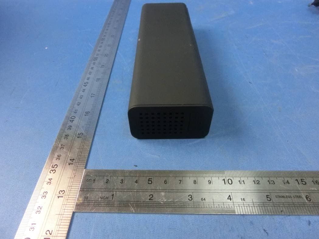
Click to zoom
Application Details
- Equipment Class
- DTS - Digital Transmission System
- Date of Grant
- Sep 21, 2015
- Application Purpose
- Original Equipment
- Date of Application
- Sep 20, 2015
- Equipment Note
- WiFi/Bluetooth LED Indicator Panel
- Frequency Range
- 2412.00000000 - 2462.00000000
- Company
- Smart Atoms Limited
- Country
- United Kingdom
Documents & Files
Document Text
Text extracted from the exhibit documents filed with the FCC. Open a document above to read the original.
Users Manual
LaMetric Time User guide Table of contents 1.Meet LaMetric 2. Safety and handling 3.Get started in 3 easy steps 3.1. Step 1. Turn on the device 3.2. Step 2. Download smartphone app 3.3. Step 3. Register and configure the device 3.3.1. Registration 3.3.2. Configuration 3.3.3. Errors of configuration process 4. Configuration via application 4.1. Manage Devices 4.1.1. LaMetric is Available 4.1.2. LaMetric is Not Available 4.1.3. Add another device 4.2. Basic apps configuration 4.2.1. Alarm Clock 4.2.2. Weather 4.2.3. Radio 4.2.4. Stopwatch 4.2.5. Timer 4.3. Apps management 4.3.1. Apps reordering 4.3.2. Apps duplicating 4.3.3. Apps removing 4.4. Working modes 4.4.1. Click to scroll apps 4.4.2. Auto Scroll apps 4.4.3. Show one app 4.5. Install apps from LaMetric Store 4.6. Device Settings 4.6.1. Brightness control 4.6.2. Volume control 4.6.3. Wi-Fi connection 4.6.4. On/Off Bluetooth speaker 4.6.5. Software update 4.6.6. System information 4.6.7. Privacy 5. Device usage 5.1. Switching on 5.2. Using apps and navigation between them 5.2.1. Using apps 5.2.2. Navigation between apps 5.3. Streaming music on LaMetric 1 5.4. Charging 5.5. Switching off 5.6. Resetting to factory defaults 5.7. Device notifications 5.7.1. Operating system notifications 5.7.2. Errors notifications 6. Create Apps for LaMetric 6.1. Getting started 6.2. Indicator Apps 6.3. Button Apps 6.4. Create App using Template 6.6. Searching and creating icons 7. Customer support 8. Regulations 8.1. FCC Information and Copyright 8.2. FCC RF warning statement 9. Warranty 10. Contact 2 1.Meet LaMetric 1. Screen 2. Ambient Light Sensor 3. Left navigation button 4. Action button 5. Right navigation button 6. Micro-USB connector 7. Audio out 8. Speaker 9. Volume down 10. Volume up 11. Speaker 12. On/Off 3 2. Safety and handling Before you start using LaMetric, please read this information to ensure your own safety and extend the service life of your device. 1. LaMetric can be damaged if dropped or burned. Don’t use a damaged LaMetric, as it may cause injury. Don’t attempt to repair LaMetric yourself. 2. Do not disassemble or modify the device. Modification or disassembly of the device could result in fire or electrical shock. 3. Do not expose your device to excessively high or low temperatures. Avoid direct sunlight. 4. Avoid heating or cooling the battery. An excessively hot battery may cause skin burns. 5. Avoid exposure to liquids or damp (do not use the device in the rain, in the street at higher humidity, near bodies of water etc.). Avoid penetration of liquids or moisture since this may cause short circuit and/or damage to the battery. 6. Avoid any mechanical pressure on the screen. Protect the screen from objects that may scratch or damage it. 7. Do not put objects on your LaMetric. 8. Do not place your device on an unstable, slant or vibrant surface. 9. Use device only with original power adapter and USB cable. 10. Use only original software. 11. Use LaMetric only indoor. 12. Use your device carefully to enjoy it longer. 4 3.Get started in 3 easy steps Now you are holding LaMetric in your hands and can not wait to start using it. Follow three easy steps to start. 3.1. Step 1. Turn on the device Connect LaMetric to a power outlet via USB cable and power adapter. Press the On/Off button to start up your LaMetric. Look at LaMetric screen and you will see an invitation to setup - It means that your device is waiting while you configure it via mobile app. 3.2. Step 2. Download smartphone app Visit go.lametric.com from your smartphone to download iOS or Android app. 3.3. Step 3. Register and configure the device 3.3.1. Registration At first, you should create an account that will be connected to your device, so nobody else will be able to change your settings. 1. Open LaMetric app on your smartphone by tapping and choose “Sign up”. 5 2. Enter your email, name and password (it should be no less than 6 symbols). Confirm password on the last field. iOS Android 3. Tap Sign up to complete registration process. 3.3.2. Configuration Now you can start to configure your device. 1. Make sure LaMetric is ready. Look at LaMetric, it should be waiting connection from your phone or tablet. Tap Next to continue. 6 2. Connect to LaMetric. Now you can see unique name of your LaMetric on the screen. You should connect your smartphone or tablet to the Wi-Fi network with this name. ● If you use iPhone, just press the Home button on your smartphone and go to your iPhone’s Wi-Fi settings. Choose network with the name which you see on LaMetric. Come back to LaMetric app. ● If you use Android, simply choose a network with the same name which you see on LaMetric. iOS Android 3. Connect LaMetric to home/office Wi-Fi network. Select your home or office Wi-Fi network, which you usually use, to connect LaMetric to and enter the password. Tap Set up in the right corner on iPhone, or tap Next on Android smartphone to continue. iOS Android 7 4. Wait a few seconds while LaMetric is connecting to Wi-Fi network. 5. Time at LaMetric. Congratulations, your LaMetric is ticking now! You can press the Right or Left navigation button to switch between basic apps as well. But this is not the end! You might want to continue device configuration and make it show other information. You just need to tap Go when such screen appears. Do you see LaMetric with a clock on the screen? Tap it to open a screen, where you can adjust settings of basic applications. 8 Read 4. Configuration via application to know how to manage 4.2.1.Alarm Clock, 4.2.2.Weather, 4.2.3.Radio, 4.2.4. Stopwatch, 4.2.5. Timer app or how to 4.5 Install/Update apps from the LaMetric Store. 3.3.3. Errors of configuration process If for some reason you can not configure your device, select a possible case among following, depending on the screen that arises: 1. If you see this screen, it means that configuration process was interrupted and not completed. Just tap + to s…
Text truncated - open the document above for the full version.
Cover Letter(s)
SCS-F18: Project and Product Certification Representative Authorization Letter Page 1 of 2 Rev 5.0 775 Montague Expressway Milpitas, CA 95035 Tel: 408-526-1188 Fax: 408-526-1088 Email: [email protected] Project and Product Certification Representative Authorization Letter Reason for Amendment (current / obsolete) Revision History Approved Date From To Initial Release (obsolete) 1.0 1.0 Nov-14-2006 Revised wording (obsolete) 1.0 2.0 Sept–25-2007 Updated company template (obsolete) 2.0 3.0 Jan-31-2012 Updated letter information (obsolete) 3.0 4.0 May-23-2014 Added FCC ID field (current) 4.0 5.0 Sept 16 2014 SCS-F18: Project and Product Certification Representative Authorization Letter Page 2 of 2 Rev 5.0 Smart Atoms Limited 2015-09-09 To: SIEMIC, INC. 775 Montague Expressway, Milpitas, CA 95035 USA Dear Sir/Madam, Re: Product Certification Representative Authorization Letter We, ____ Smart Atoms Limited __ hereby authorize SIEMIC, Inc. to act as a Certification Body for certifying for the following project(s): Product: WiFi/Bluetooth LED Indicator Panel Trade Name: LaMetric Model Name: LM 37X8 Serial Model: LM 37X8B, LM 37X8C, LM 37X8M, LM 37X8S, LM 37X8W FCC ID: 2AE8C-SA1 Sincerely, Signature Client’s name / title : Nazar Bilous / Sales assistant Contact information / address : 39C Fermoy Road, London, W9 3NH, United Kingdom
Cover Letter(s)
SCS-F19: Confidentiality Request Letter Page 1 of 2 Rev 4.0 775 Montague Expressway Milpitas, CA 95035 Tel: 408-526-1188 Fax: 408-526-1088 Email: [email protected] Confidentiality Request Letter Reason for Amendment (current / obsolete) Revision History Approved Date From To Initial Release (obsolete) 1.0 1.0 Nov-14-2006 Adding CFR 2.459 (obsolete) 1.0 2.0 August – 11 - 2008 Updated company template & Added text box (obsolete) 2.0 3.0 Jan-31-2012 Added IC confidentiality letter form (current) 3.0 4.0 March-26-2015 SCS-F19: Confidentiality Request Letter Page 2 of 2 Rev 4.0 Smart Atoms Limited 2015-09-09 To: Federal Communications Commission Authorization and Evaluation Division 7435 Oakland Mills Road Columbia, MD Subject: Permanent Confidentiality Request for FCC ID:2AE8C-SA1 We hereby request confidential treatment of information accompanying this application as outlined below: - . Block Diagram - Schematics - Operational Description - The above materials contain trade secrets and proprietary information not customarily released to the public. The public disclosure of these materials may be harmful to the applicant and provide unjustified benefits to its competitors. The applicant understands that pursuant to Section 0.457 & 0.459 of the Rules, disclosure of this application and all accompanying documentation will not be made before the date of the Grant for this application. Sincerely, Signature Client’s name / title : Nazar Bilous / Sales assistant Contact information / address : 39C Fermoy Road, London, W9 3NH, United Kingdom
Cover Letter(s)
Smart Atoms Limited WIFI Channel 12 & 13 Declaration Letter To whom it may concern : We have declared below featured for FCC equipment authorization in regard to 802.11b/g/n channel 12 & 13 operating capability for FCC ID : 2AE8C-SA1 Please check Product hardware does not have the capability to operate on channel 12 & 13 Product hardware has the capability to operate on channel 12 & 13. However , these 2 channels will be disabled via software and user will not able to enable these 2 channels Product hardware has the capability to operate on channel 12 & 13. And meeting KDB 594280 D01 requirement. Pls explain detail here. Others Pls explain detail here. Signature Client’s name / title : Nazar Bilous / Sales assistant Contact information / address : 39C Fermoy Road, London, W9 3NH, United Kingdom
Cover Letter(s)
Smart Atoms Limited Model Difference FCC ID: 2AE8C-SA1 Model : LM 37X8, LM 37X8B, LM 37X8C, LM 37X8M, LM 37X8S, LM 37X8W All the model are the same circuit and RF module, except the model name and colour. Regards, Client’s signature Signature Client’s name / title : Nazar Bilous / Sales assistant Contact information / address : 39C Fermoy Road, London, W9 3NH, United Kingdom
External Photos
APPENDIX-PHOTOGRAPHS OF EUT CONSTRUCTIONAL DETAILS Photo 1 Photo 2 Photo 3 Photo 4 Photo 5 Photo 6 Photo 7
ID Label/Location Info
FCC ID LABELING AND LOCATION FCC ID Label WiFi/Bluetooth LED Indicator Panel Model NO.: LM 37X8 FCC ID:2AE8C-SA1 FCC ID Label Location The label shown shall be permanently affixed at a conspicuous location on the device and be readily visible to the user at the time purchase (Labeling requirements per 2.925)
Internal Photos
APPENDIX-PHOTOGRAPHS OF EUT CONSTRUCTIONAL DETAI Photo 1 Photo 2 Photo 3 Photo 4 Photo 5 Photo 6 Photo 7 Photo 8 Photo 9 Photo 10 Photo 11 Photo 12 BT/WiFi Antenna Photo 13
RF Exposure Info
FCC ID : 2AE8C-SA1 RF EXPOSURE EVALUATION METHOD FCC ID:2AE8C-SA1 SAR Test Exclusion Thresholds for 100 MHz – 6 GHz and ≤ 50 mm Approximate SAR Test Exclusion Power Thresholds at Selected Frequencies and Test Separation Distances are illustrated in the following Table. The 1-g and 10-g SAR test exclusion thresholds for 100 MHz to 6 GHz at test separation distances ≤ 50 mm are determined by: [(max. power of channel, including tune-up tolerance, mW)/(min. test separation distance, mm)] · [√f(GHz)] ≤ 3.0 for 1-g SAR and ≤ 7.5 for 10-g extremity SAR,where f(GHz) is the RF channel transmit frequency in GHz Power and distance are rounded to the nearest mW and mm before calculation The result is rounded to one decimal place for comparison The test exclusions are applicable only when the minimum test separation distance is ≤ 50 mm and for transmission frequencies between 100 MHz and 6 GHz. When the minimum test separation distance is < 5 mm, a distance of 5 mm is applied to determine SAR test exclusion. Maximum measured transmitter power. WIFI: TX 802.11b Mode Te s t Channe Frequency Maximum Peak Conducted Output Power(PK) Maximum Peak Conducted Output Power(AV) Maximum Peak Conducted Output Power (AV) (MHz) (dBm) (dBm) mW CH01 2412 12.71 9.39 8.690 CH06 2437 12.73 9.21 8.337 CH11 2462 12.74 9.42 8.750 TX 802.11g Mode CH01 2412 12.45 9.22 8.356 CH06 2437 12.52 9.39 8.690 CH11 2462 12.49 9.36 8.630 TX 802.11n(20) Mode CH01 2412 12.25 8.02 6.339 CH06 2437 12.24 8.01 6.324 CH11 2462 12.35 8.12 6.486 TX 802.11n(40) Mode CH03 2422 10.85 8.62 7.278 CH06 2437 10.84 8.61 7.261 CH09 2452 10.81 8.58 7.211 FCC ID : 2AE8C-SA1 BT 3.0 1Mbps Test Channel Frequency (MHz) Peak Output Power (dBm) Peak Output Power (mW) CH00 2402 6.18 4.150 CH39 2441 6.53 4.498 CH78 2480 6.00 3.981 Remark: The best case gain of the antenna is 3.0dBi. 3.0 dBi logarithmic terms convert to numeric result is nearly 1.96 The 1-g and 10-g SAR test exclusion thresholds for 100 MHz to 6 GHz at test separation distances ≤ 50 mm are determined by: [(max. power of channel, including tune-up tolerance, mW)/(min. test separation distance,mm)] · [√f(GHz)] WIFI: Te s t Channel Range tune up max power (dBm) [(max. power of channel, including tune-up tolerance, mW) (min. test separation distance,mm)] [f(GHz)] Result Limit TX 802.11b Mode CH01 7.6~9.6 9.6 9.120 5 2.412 2.83 3 CH06 7.6~9.6 9.6 9.120 5 2.437 2.85 3 CH11 7.6~9.6 9.6 9.120 5 2.462 2.86 3 TX 802.11g Mode CH01 7.6~9.6 9.6 9.120 5 2.412 2.83 3 CH06 7.6~9.6 9.6 9.120 5 2.437 2.85 3 CH11 7.6~9.6 9.6 9.120 5 2.462 2.86 3 TX 802.11n-HT20 Mode CH01 7.0~9.0 9.0 7.943 5 2.412 2.47 3 CH06 7.0~9.0 9.0 7.943 5 2.437 2.48 3 CH11 7.0~9.0 9.0 7.943 5 2.462 2.49 3 TX 802.11n-HT40 Mode CH03 6.0~8.0 8.0 6.310 5 2.422 1.96 3 CH06 6.0~8.0 8.0 6.310 5 2.437 1.97 3 CH09 6.0~8.0 8.0 6.310 5 2.452 1.98 3 FCC ID : 2AE8C-SA1 BT 3.0 Te s t Channel Range tune up max power (dBm) [(max. power of channel, including tune-up tolerance, mW) (min. test separation distance,mm)] [f(GHz)] Result Limit 1Mbps CH00 5~7 7 5.012 5 2.402 1.554 3 CH39 5~7 7 5.012 5 2.441 1.566 3 CH78 5~7 7 5.012 5 2.480 1.579 3 The test Result is less than 3.0 for 1-g SAR and ≤ 7.5 for 10-g extremity SAR. Conclusion: No SAR is required.
Test Report
FCC RADIO TEST REPORT FCC ID: 2AE8C-SA1 Product: WiFi/Bluetooth LED Indicator Panel Trade Name: LaMetric Model Name: LM 37X8 Serial Model: LM 37X8B, LM 37X8C, LM 37X8M, LM 37X8S, LM 37X8W Report No.: NTEK-2015NT0528043F2 Prepared for Smart Atoms Limited 39C Fermoy Road, London, W9 3NH, United Kingdom Prepared by Shenzhen NTEK Testing Technology Co., Ltd. 1/F, Building E, Fenda Science Park, Sanwei Community, Xixiang Street Bao’an District, Shenzhen P.R. China Tel.: +86-0755-61156588 Fax.: +86-0755-61156599 Website:www.ntek.org.cn Page 2 of 61 Report No.: NTEK-2015NT0528043F2 TEST RESULT CERTIFICATION Applicant’s name ........ Smart Atoms Limited Address ........................ 39C Fermoy Road, London, W9 3NH, United Kingdom Manufacture's Name ... Shenzhen Futaihong Precision Industrial Co., Ltd. Address ........................ 3F F4 Building Foxconn Technology Group , NO.2,2nd Donghuan Road , 10th Yousong Industrial District , New Distrit of LongHua Shenzhen Guangdong Province China Product description Product name .................WiFi/Bluetooth LED Indicator Panel Model and/or type reference ..................... LM 37X8 Serial Model .................... LM 37X8B, LM 37X8C, LM 37X8M, LM 37X8S, LM 37X8W Standards .................... FCC Part15.247 01 Oct. 2014 Test procedure ................ ANSI C63.10-2013 and KDB 558074: June 5, 2014 This device described above has been tested by NTEK, and the test results show that the equipment under test (EUT) is in compliance with the FCC requirements. And it is applicable only to the tested sample identified in the report. This report shall not be reproduced except in full, without the written approval of NTEK, this document may be altered or revised by NTEK, personnel only, and shall be noted in the revision of the document. Date of Test ...................................... Date (s) of performance of tests ....... 28 May 2015~14 Jul. 2015 Date of Issue ..................................... 14 Jul. 2015 Test Result ......................................... Pass Testing Engineer : Denny Huang Technical Manager : (Brown Lu) Authorized Signatory : (Sam Chen) Page 3 of 61 Report No.: NTEK-2015NT0528043F2 Table of Contents Page 1 . SUMMARY OF TEST RESULTS 5 1.1 TEST FACILITY 6 1.2 MEASUREMENT UNCERTAINTY 6 2 . GENERAL INFORMATION 7 2.1 GENERAL DESCRIPTION OF EUT 7 2.2 DESCRIPTION OF TEST MODES 9 2.3 BLOCK DIGRAM SHOWING THE CONFIGURATION OF SYSTEM TESTED 10 2.4 DESCRIPTION OF SUPPORT UNITS(CONDUCTED MODE) 11 2.5 EQUIPMENTS LIST FOR ALL TEST ITEMS 12 3 . EMC EMISSION TEST 14 3.1 CONDUCTED EMISSION MEASUREMENT 14 3.1.1 POWER LINE CONDUCTED EMISSION LIMITS 14 3.1.2 TEST PROCEDURE 15 3.1.3 DEVIATION FROM TEST STANDARD 15 3.1.4 TEST SETUP 15 3.1.5 EUT OPERATING CONDITIONS 15 3.1.6 TEST RESULTS 16 3.2 RADIATED EMISSION MEASUREMENT 24 3.2.1 RADIATED EMISSION LIMITS 24 3.2.2 TEST PROCEDURE 25 3.2.3 DEVIATION FROM TEST STANDARD 25 3.2.4 TEST SETUP 26 3.2.5 EUT OPERATING CONDITIONS 27 3.2.6 TEST RESULTS (BETWEEN 9KHZ – 30 MHZ) 28 3.2.7 TEST RESULTS (BETWEEN 30MHZ – 1GHZ) 29 3.2.8 TEST RESULTS (ABOVE 1000 MHZ) 31 4 . POWER SPECTRAL DENSITY TEST 32 4.1 APPLIED PROCEDURES / LIMIT 32 4.1.1 TEST PROCEDURE 32 4.1.2 DEVIATION FROM STANDARD 32 4.1.3 TEST SETUP 32 4.1.4 EUT OPERATION CONDITIONS 32 4.1.5 TEST RESULTS 33 5 . BANDWIDTH TEST 41 5.1 APPLIED PROCEDURES / LIMIT 41 5.1.1 TEST PROCEDURE 41 Page 4 of 61 Report No.: NTEK-2015NT0528043F2 Table of Contents Page TEST SETUP 41 5.1.2 EUT OPERATION CONDITIONS 41 5.1.3 TEST RESULTS 42 6 . PEAK OUTPUT POWER TEST 50 6.1 APPLIED PROCEDURES / LIMIT 50 6.1.1 TEST PROCEDURE 50 6.1.2 DEVIATION FROM STANDARD 50 6.1.3 TEST SETUP 50 6.1.4 EUT OPERATION CONDITIONS 50 6.1.5 TEST RESULTS 51 7 . 100 KHZ BANDWIDTH OF FREQUENCY BAND EDGE 52 7.1 DEVIATION FROM STANDARD 52 7.2 TEST SETUP 52 7.3 EUT OPERATION CONDITIONS 52 7.4 TEST RESULTS 53 8 . ANTENNA REQUIREMENT 59 8.1 STANDARD REQUIREMENT 59 8.2 EUT ANTENNA 59 9 . EUT TEST PHOTO 60 APPENDIX-PHOTOGRAPHS OF EUT CONSTRUCTIONAL DETAILS Page 5 of 61 Report No.: NTEK-2015NT0528043F2 1. SUMMARY OF TEST RESULTS Test procedures according to the technical standards: FCC Part15 (15.247) , Subpart C Standard Section Test Item Judgment Remark 15.207 Conducted Emission PASS 15.247 (a)(2) 6dB Bandwidth PASS 15.247 (b) Peak Output Power PASS 15.247 (c) Radiated Spurious Emission PASS 15.247 (d) Power Spectral Density PASS 15.205 Band Edge Emission PASS 15.203 Antenna Requirement PASS NOTE: (1)” N/A” denotes test is not applicable in this Test Report Page 6 of 61 Report No.: NTEK-2015NT0528043F2 1.1 TEST FACILITY NTEK Testing Technology Co., Ltd Add.:1/F, Building E, Fenda Science Park, Sanwei Community, Xixiang Street, Bao’an District, Shenzhen P.R. China. FCC Registration No.:238937; IC Registration No.:9270A-1 CNAS Registration No.:L5516 1.2 MEASUREMENT UNCERTAINTY The reported uncertainty of measurement y ± U,where expended uncertainty U is based on a standard uncertainty multiplied by a coverage factor of k=2,providing a level of confidence of approximately 95 %。 No. Item Uncertainty 1 Conducted Emission Test ±1.38dB 2 RF power,conducted ±0.16dB 3 Spurious emissions,conducted ±0.21dB 4 All emissions,radiated(<1G) ±4.68dB 5 All emissions,radiated(>1G) ±4.89dB 6 Temperature ±0.5°C 7 Humidity ±2% Page 7 of 61 Report No.: NTEK-2015NT0528043F2 2. GENERAL INFORMATION 2.1 GENERAL DESCRIPTION OF EUT Equipment WiFi/Bluetooth LED Indicator Panel Trade Name LaMetric Model Name LM 37X8 Serial Model LM 37X8B, LM 37X8C, LM 37X8M, LM 37X8S, LM 37X8W Model Difference All the model are the same circuit and RF module, except the model name and colour. Product Description Operation Frequency: 802.11b/g/n(20MHz): 2412~2462MHz 802.11n(40MHz):2422~2452MHz Modulation Type: IEEE 802.11b : DSSS (CCK, QPSK, DBPSK) IEEE 802.11g/n (HT20/HT40) : OFDM(64QAM, 16QAM, QPSK, BPSK) Bit Rate of Transmitter 802.11b:11/5.5/2/1 Mbps 802.11g:54/48/36/24/18/12/9/6Mbps 802.11n(20MHz/40MHz):150/144.44/1 30/117/115.56/104/86.67/78/52…
Text truncated - open the document above for the full version.
Test Setup Photos
Page 60 of 61 Report No.: NTEK-2015NT0528043F2 9. EUT TEST PHOTO Radiated Measurement Photos Page 61 of 61 Report No.: NTEK-2015NT0528043F2 CONDUCTED EMISSION Photos
Contact Information
Applicant
Nazar Bilous
Test Firm
Shenzhen NTEK Testing Technology Co., Ltd.Jason Chen
Technical Specifications
| # | Rule Parts | Frequency Range | Power Output |
|---|---|---|---|
| 1 | 15C | 2.41 GHz - 2.46 GHz | 18.79 mW |
Other Applications from Smart Atoms Limited
2AE8C-SA5
Oct 20, 2022LaMetric SKY
Equipment Class
DTS - Digital Transmission System