2AEAV001Kisai Link
T.F. Watches Limited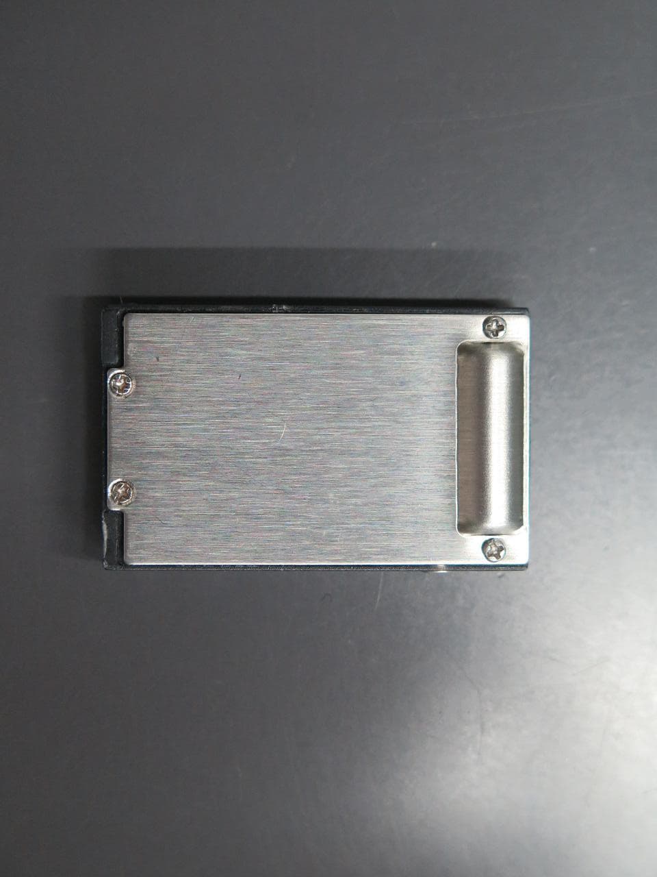
Click to zoom
Application Details
- Equipment Class
- DXX - Part 15 Low Power Communication Device Transmitter
- Date of Grant
- Mar 31, 2015
- Application Purpose
- Original Equipment
- Date of Application
- Mar 31, 2015
- Equipment Note
- Kisai Link
- Frequency Range
- 2402.00000000 - 2480.00000000
- Company
- T.F. Watches Limited
- Country
- Hong Kong
Documents & Files
Document Text
Text extracted from the exhibit documents filed with the FCC. Open a document above to read the original.
Users Manual
Kisai Link User Guide Quick Start Instructions Fully charge Kisai Link before use. Connect the USB charging cable provided to the charging point on Kisai Link and connect the charging cable to a USB power source. Three colored LEDs will animate when charging is in progress. When Kisai Link is 100% charged the LEDs will turn OFF. Download the Kisai Bridge app from the Apple App Store or the Google Play Store to your smartphone. Enable Bluetooth in your smartphone settings, open the Kisai Bridge app and go to the pairing page. Press the Function button on Kisai Link once to wake the device and three LEDs will blink once. Press SCAN on the pairing page and select Kisai Link. When successfully paired, the device name on the app will turn blue. User Guide 1. How do I charge Kisai Link? 2. How do I download the Kisai Bridge application? 3. How do I pair Kisai Link with my iPhone? 4. How do I re-pairing Kisai Link with my iPhone? 5. How do I pair with a different Kisai device or smartphone? 6. How do I set up the notifications I want to receive? 7. What happens when I receive an incoming call alert? 8. What happens when I receive an incoming mail alert? 9. How do I set up SMS and social media alerts? 10. How do I use the Proximity Alert? 11. How do I find my iPhone? 12. How do I use Power Saving Mode? 13. How do I use the alarm function? 14. How do I restore factory settings? 15. Battery Information 16. Warranty 17. Water Resistance 18. Setting Up Facebook as a Social Alert 19. Setting Up Facebook Messenger as a Social Alert 20. Setting Up Twitter as a Social Alert 21. Setting Up LINE as a Social Alert 22. Setting Up WhatsApp as a Social Alert 23. Setting Up Skype as a Social Alert 1. How do I charge Kisai Link? 1.1 Fully charge Kisai Link before using it for the first time. 1.2 Connect the USB charging cable provided to the charging point on Kisai Link. 1.3 Connect the charging cable to a USB power source. 1.4 Three colored LEDs will animate in sequence when charging is in progress. 1.5 When Kisai Link is 100% charged the LEDs will turn OFF. 1.6 You will not be able to use Kisai Link during charging. 1.7 Only use the cable provided to charge Kisai Link. 2. How do I download the Kisai Bridge application? 2.1 Download the Kisai Bridge app from the Apple App Store. 2.2 When you download the app, allow push notifications if you want to receive battery low notifications. 2.3 Please note, some functions on the application will not be activated for use with Kisai Link. 3. How do I pair Kisai Link with my iPhone? 3.1 Enable Bluetooth in your iPhone settings > Bluetooth > ON. 3.2 Open the Kisai Bridge app and go to the pairing page. 3.3 Press the Function button on Kisai Link once to wake the device and three LEDs will blink once. 3.4 Press SCAN on the app and select Kisai Link from the pairing page. 3.5 When successfully paired, the device name on the app will turn blue and the Bluetooth indicator on the device will flash. 3.6 If you do not pair after 1 minute, Kisai Link will go to sleep. 3.7 If no device is found after 30 seconds of searching, the message "no device found" will appear and searching will stop. 3.8 If no device is found, make sure Kisai Link is awake by pressing the activation button & press "SCAN" on the pairing page of the app. 3.9 If you need to confirm that Kisai Link is connected, view your iPhone settings > Bluetooth and check which devices are connected. 4. How do I re-pairing Kisai Link with my iPhone? 4.1 If your iPhone is out of range of Kisai Link for more than 60 minutes, the connection will be lost & Kisai Link will go to sleep. 4.2 When back in range, press the Function button on Kisai Link and it will automatically re-pair. 5. How do I pair with a different Kisai device or smartphone 5.1 When you want to use a different Kisai device with your smartphone, you should disconnect the device you currently have connected. 5.2 On the pairing page of the Kisai Bridge app, press & hold the device that is currently connected for 3 seconds and it will be disconnected. 5.3 Pair the new device. 5.4 The product code for each device is unique for each iPhone so you can distinguish between devices. 6. How do I set up the notifications I want to receive? 6.1 On the app settings page, select the notifications you wish to receive: [call alert] [email alert] [social alert] [proximity alert]. 6.2 On the app settings page, you can choose [LED only] [vibration only] or [LED and vibration] for notifications. 6.3 It is not possible to turn off both vibration & LED. 6.4 Email alerts and social alerts are connected to the notification centre in iPhone. 6.5 To clear notifications on Kisai Link, press the function button on Kisai Link or clear the items listed in the notification centre in your iPhone. 6.6 When you receive a new notification, Kisai Link will also notify you again of any other outstanding notifications. 6.7 The number of notifications you receive for each application (apart from calls) is managed from your iPhone Notification Centre for each app. 7. What happens when I receive an incoming call alert? 7.1 Incoming Call Alert allows you to receive a notification when you receive a call. 7.2 When you receive a call the red LED will flash quickly and Kisai Link will vibrate. 7.3 When you have a missed call the red LED will flash slowly. 7.4 You can receive call notifications when your smartphone is in manner mode & vibration turned off. 8. What happens when I receive an incoming mail alert? 8.1 Mail Alert allows you to receive a notification when you receive an email. 8.2 When you receive an email the blue LED will flash and Kisai Link will vibrate. 8.3 To receive mail notifications you must allow notifications for mail in your iPhone: Settings > Notifications > Mail [Allow Notifications] and Show in Notification Centre > [1] [5] or [10] notifications. 8.4 On iPhone, you can receive email notifications from any email account accessed through the iPhone Mail application. 8.5 You can rece…
Text truncated - open the document above for the full version.
Cover Letter(s)
T. F. WATCHES LIMITED Unit 11, 10/F, ASIA Trade Centre 79 LEI MUK ROAD KWAI CHUNG Hong Kong Tel: (852) 24282198 10 Mar 2015 Equipment Authorization Division Office id Engineering and Technology Federal Communications Commission 7435 Oakland Mills Road Columbia, MD 21046 Dear Sirs: T. F. Watches Limited requests acceptance of the labeling proposal described below for Kasai Link bearing FCC identifier 2AEAV001. The subject Kasai Link models as shown in figure 1, authorized under FCC Part 15 Class C figure 1 T. F. WATCHES LIMITED Unit 11, 10/F, ASIA Trade Centre 79 LEI MUK ROAD KWAI CHUNG Hong Kong Tel: (852) 24282198 It is because the surface of the device does not enough to indicate the FCC statement. For this reason, T. F. Watches Limited proposes those statements is showing on the user manual and the device is carrying the FCC ID number only. The figure2 is showing the FCC ID location. figure 2 Sincerely, T. F. Watches Limited ------------------------------- Paul Cooper Marketing Manager
External Photos
External Photo
ID Label/Location Info
Label Sample
Internal Photos
Internal Photo
Test Report
TEST REPORT Report No. : AT0011904(4) Date : 24 Mar 2015 For and on behalf of CMA Industrial Development Foundation Limited Authorized Signature : Page 1 of 34 Mr. WONG Lap-pong, Andrew Manager Electrical Division FCC ID: 2AEAV001 Application No. : LT006601(2) Applicant : T. F. Watch Ltd Unit 11, 10/F, Asia Trade Centre, No. 79 Lei Muk Road, Kwai Chung, NT Sample Description : One(1) item of submitted sample stated to be Kisai Link of Model No. L001 Sample registration No. : RT010049-001 Radio Frequency : 2402MHz – 2480 MHz Transceiver Rating : 3.7V rechargeable battery No. of submitted sample : Four (4) piece (s) Date Received : 06 Feb 2015 Test Period : 09 Feb 2015 to 25 Feb 2015. Test Requested : FCC Part 15 Certificate Test Method : 47 CFR Part 15 (10-1-14 Edition), ANSI C63. 4 – 2009 Test Engineer : Mr. LEUNG Shu-kan, Ken Test Result : See attached sheet(s) from page 2 to 34. Conclusion : The submitted sample was found to comply with requirement of FCC Part 15 Subpart B and C. TEST REPORT Report No. : AT0011904(4) Date : 24 Mar 2015 Page 2 of 34 FCC ID: 2AEAV001 Table of Contents 1 General Information ................................................................................................................................... 3 1.1 General Description ............................................................................................................................ 3 1.2 Location of the test site ....................................................................................................................... 4 1.3 List of measuring equipment............................................................................................................... 5 1.4 Support equipment .............................................................................................................................. 5 1.5 Measurement Uncertainty ................................................................................................................... 6 2 Description of the radiated emission test ................................................................................................... 7 2.1 Test Procedure .................................................................................................................................... 7 2.2 Test Result .......................................................................................................................................... 8 2.3 Radiated Emission Measurement Data ............................................................................................... 9 3 Description of the Line-conducted Test ................................................................................................... 13 3.1 Test Procedure .................................................................................................................................. 13 3.2 Test Result ........................................................................................................................................ 13 3.3 Graph and Table of Conducted Emission Measurement Data .......................................................... 13 4 Photograph ............................................................................................................................................... 14 4.1 Photographs of the Test Setup for Radiated Emission and Conducted Emission ............................. 14 4.2 Photographs of the External and Internal Configurations of the EUT .............................................. 14 5 Supplementary document ......................................................................................................................... 15 5.1 Bandwidth ......................................................................................................................................... 15 5.2 Duty cycle ......................................................................................................................................... 15 5.3 Transmission time ............................................................................................................................. 15 5.4 Power Spectral Density ..................................................................................................................... 15 5.5 Average on time ................................................................................................................................ 15 6 Appendices ............................................................................................................................................... 16 TEST REPORT Report No. : AT0011904(4) Date : 24 Mar 2015 Page 3 of 34 FCC ID: 2AEAV001 1 General Information 1.1 General Description The equipment under test (EUT) is a 2.4GHz wireless device. The EUT is powered by 3.7V rechargeable battery. The EUT will connect smart phone through wireless connection. When there is incoming call, the smart phone will transmit signal to EUT to inform the user there is a call The brief circuit description is listed as follows: - X1, X2 and its associated circuit act as oscillator - U1 and its associated circuit act as MCU - U4, U5 and its associated circuit act as flash memory - U2, U3 and its associated circuit act as voltage regulator - J3 and its associated circuit act as RF module Device: BLE device Frequency Range: 2402-2480 MHz Number of channels: 40 Modulation: GFSK Antenna: PCB strip antenna Antenna gain: 0dB Operating power: 2402-2480 Maximum power 88.5 dB μV/m @ 3 meters Frequency channel: Channel Frequency Channel Frequency Channel Frequency Channel Frequency 1 2404 MHz 11 2424 MHz 21 2446 MHz 31 2466 MHz 2 2406 MHz 12 2428 MHz 22 2448 MHz 32 2468 MHz 3 2408 MHz 13 2430 MHz 23 2450 MHz 33 2470 MHz 4 2410 MHz 14 2432 MHz 24 2452 MHz 34 2472 MHz 5 2412 MHz 15 2434 MHz 25 2454 MHz 35 2474 MHz 6 2414 MHz 16 2436 MHz 26 2456 MHz 36 2476 MHz 7 2416 MHz 17 2438 MHz 27 2458 MHz 37 2478 MHz 8 2418 MHz 18 244…
Text truncated - open the document above for the full version.
Test Report
TEST REPORT Report No. : AT0011904(4) Date : 25 Feb 2015 Tested by: Reviewed by: Mr. LEUNG Shu-kan, Ken Mr. WONG Lap-pong, Andrew Page 27 of 32 FCC ID: 2AEAV001 A6 Conducted Emission Measurement Date TEST REPORT Report No. : AT0011904(4) Date : 25 Feb 2015 Tested by: Reviewed by: Mr. LEUNG Shu-kan, Ken Mr. WONG Lap-pong, Andrew Page 28 of 32 FCC ID: 2AEAV001 A6 Conducted Emission Measurement Date
Test Report
TEST REPORT Report No. : AT0011904(4) Date : 25 Feb 2015 Tested by: Reviewed by: Mr. LEUNG Shu-kan, Ken Mr. WONG Lap-pong, Andrew Page 29 of 32 FCC ID: 2AEAV001 A7. Band Edge Lower edge (Peak measurement) Lower edge (Average measurement) TEST REPORT Report No. : AT0011904(4) Date : 25 Feb 2015 Tested by: Reviewed by: Mr. LEUNG Shu-kan, Ken Mr. WONG Lap-pong, Andrew Page 30 of 32 FCC ID: 2AEAV001 A7. Band Edge Higher edge (Peak measurement) Higher edge (Average measurement)
Test Report
TEST REPORT Report No. : AT0011904(4) Date : 25 Feb 2015 Tested by: Reviewed by: Mr. LEUNG Shu-kan, Ken Mr. WONG Lap-pong, Andrew Page 31 of 32 FCC ID: 2AEAV001 A8. 20dB Bandwidth Plot Bandwidth 1 (2402MHz) Bandwidth 2 (2440MHz) TEST REPORT Report No. : AT0011904(4) Date : 25 Feb 2015 Tested by: Reviewed by: Mr. LEUNG Shu-kan, Ken Mr. WONG Lap-pong, Andrew Page 32 of 32 FCC ID: 2AEAV001 A8. 20dB Bandwidth Plot Bandwidth 3 (2480MHz) ***** End of Report *****
Test Setup Photos
Test Setup Photo Front view (30MHz – 1GHz) Rear view (30Mz – 1GHz) Front view (9kHz – 30MHz) Rear view (9kHz – 30MHz) Front view (1GHz – 25GHz) Rear view (1GHz – 25GHz) Charging mode (front view) Charging mode (rear view) Conducted emission (front view) Conducted emission (rear view) Conducted Emission (side view)
Contact Information
Applicant
Paul Cooper(Marketing Manager)
Test Firm
CMA Industrial Development Foundation LimitedJoey Kwok
[email protected]+852 2690 8255
Technical Specifications
| # | Rule Parts | Frequency Range | Power Output |
|---|---|---|---|
| 1 | 15C | 2.40 GHz - 2.48 GHz | - |