2AEB4ARROWG01GPS TRACKER
Connected Holdings LLC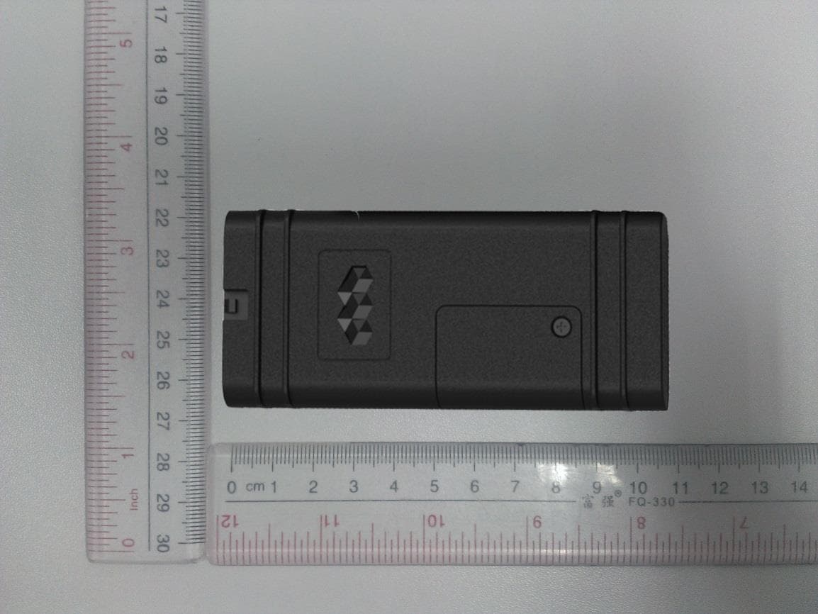
Click to zoom
Application Details
- Equipment Class
- PCB - PCS Licensed Transmitter
- Date of Grant
- Apr 21, 2015
- Application Purpose
- Original Equipment
- Date of Application
- Apr 21, 2015
- Equipment Note
- GPS TRACKER
- Frequency Range
- 1850.20000000 - 1909.80000000
- Company
- Connected Holdings LLC
- Country
- United States
Documents & Files
Document Text
Text extracted from the exhibit documents filed with the FCC. Open a document above to read the original.
Users Manual
Confidential Preliminary – Subject to Change 2015 Connected Holdings LLC Page 1 of 11 Product Description For the Arrow Vehicle Tracking Device By Connected Holdings LLC Jan 1, 2015 Document reference Revision: X1.00 Author: Mr. Edmund Lee Proofed by: Mr. Zeev Collin Release date: Date first printed above File name: ARROW_Overview_Specification_X100_030112 Authorized Recipients Executive management as provided to and are bound by a Non-Disclosure Agreement (NDA) in favor of Connected Holdings LLC, its parent or its agent and preventing disclosure or misuse of the confidential information herein. The information presented in this document is strictly confidential and contains trade secrets and other confidential information that are the exclusive property of Connected Holdings LLC, its parent, subsidiaries or agents. Confidential Preliminary – Subject to Change 2015 Connected Holdings LLC Page 2 of 11 Description The ARROW GPS Tracker is a self contained, integrated commercial grade vehicle tracking device that uses GPS satellite location in combination with a quad band GSM/GPRS cellular radio connection to report that location. All antennas including the GPS patch and GSM antenna are internal to the device. Data reporting can be initiated by a server or by the tracker itself via GSM/GPRS SMS or UDP pathways or over a physical USB connection. The ARROW is comprised of a simple two piece plastic enclosure that is snapped together for reliability, durability and low cost assembly. Interface signals and power are ported through a connector socket at one end with 8pin wire connector. The ARROW is based on chip level design as opposed to the traditional approach of using a third party communications module with an external processor. The application software executes on the base level Central Processing Unit (CPU) under direct real-time Operating System (OS) control. This approach provides a much more reliable, lower power and faster response time than module/processor architectures. Unlike common module/processor based designs; the ARROW design allows direct operating system access by the application, thus mitigating the need and for a redundant external processor and the associated power and cost. For added redundancy against system lockup, a physically separate, dedicated watchdog circuit oversees the ARROW system operation. If the system does not maintain the watchdog circuit through programmed reporting, the system power is cycled and a new GPS satellite and cellular connection is established. The ARROW can be provisioned for UDP and SMS data services for application command and/or data transactions within the 850, 900, 1800 and 1900 MHz GSM bands. Network provisioning is done using embedded SIM technology for reliability and cost savings. For added safeguard against network connection loss, a hardware ARROW endpoint reset and reboot can be initiated by simply calling the provisioned phone number and allowing it to ring three times. Flexible I/O includes 2 bidirectional General Purpose Input Output (GPIO) ports. A separate dedicated USB port is provided for general use as well as development and programming support. A high current relay drive is provided for starter motor solenoid control or general purpose drive (current sink only). Over The Air (OTA) application firmware updates are supported through at TFTP connection to a server. The entire application image can be updated using one specialized SMS or USB command. All inputs are electrically hardened against overvoltage and over current conditions present in automotive environments. This includes transient electrical noise and Electrostatic Discharge (ESD). The power input is further protected against over current with an internal self-resetting fuse. The ARROW is physically disguised to appear to be a nondescript part of the cabling system. It is a small black box with unremarkable features. Two LED status indicators are provided to verify correct installation and initial operation. A unique power Confidential Preliminary – Subject to Change 2015 Connected Holdings LLC Page 3 of 11 management feature allows these LEDs to be extinguished once installation is verified to be correct. This feature reduces power and further conceals the ION Tracker from untrained parties wishing to defeat its operation. As with all GPS location devices, the ARROW should be installed in a vehicle such that it has an unobstructed view of the sky during normal operation. Double sided foam tape can be used to secure the surface not facing the sky if needed. A factory populate option is provided to add a backup battery and motion detector to the main board. Under software control, this motion detector can be used to wake the ARROW from a very low power state. Confidential Preliminary – Subject to Change 2015 Connected Holdings LLC Page 4 of 11 Bullet Specifications ________________________________________________________________________ Cellular: 850/900/1800/1900 MHz Quad band GSM/GPRS Protocol CS-1, CS-2, CS-3 and CS-4 Output power: Class 4 (2W) @ 850/900MHz > 24dB @ 850/900MHz (OTA TRP) Class 1 (1W) @ 1800/1900MHz > 26.5dB @ 1800/1900MHz (OTA TRP) Sensitivity: < -107dBm @ 850/900MHz (Conducted) < -101dBm @ 850/900MHz (OTA TIS) < -106dBm @ 1800/1900MHz (Conducted) < -103.5dBm @ 1800/1900MHz (OTA TIS) Antenna: Integrated onto PCB Meets minimum AT&T TRP/TIS requirements ________________________________________________________________________ Services: GPRS Multi slot class 12 SMS (Text): UDP data DNS address resolution GSM circuit switched hard reboot ________________________________________________________________________ Confidential Preliminary – Subject to Change 2015 Connected Holdings LLC Page 5 of 11 ________________________________________________________________________ GPS: L1-band (1.57542GHz) Channels: 210 PRN 66 Search 22 Simultaneous tracking Sensitivity (UHIS): Tracking: -165dBm Reacquisition: -158dBm Acquisition: -149dBm Acquisition t…
Text truncated - open the document above for the full version.
External Photos
A Test Lab Techno Corp. External Photos A Test Lab Techno Corp. A Test Lab Techno Corp. A Test Lab Techno Corp.
ID Label/Location Info
1.0 ARROW-G LABELCONNECTED HOLDINGS LLCPE LABEL 25-05-14 SN: A5050019160IMEI: 352165050019160 FCC ID : 2AEB4ARROWG01IC : 20080-ARROWG01 H/W : 1.2 F/W : 1.7.6 M/N : ARROW-G P1513CV
Internal Photos
A Test Lab Techno Corp. Internal Photos A Test Lab Techno Corp. GSM Antenna A Test Lab Techno Corp.
RF Exposure Info
© 2015 A Test Lab Techno Corp. Report Number: 1504FS11 Page ‐1‐ ATestLabTechnoCorp. Changan Lab:No. 140 -1, Changan Street, Bade City, Taoyuan County, Taiwan R.O.C. Tel:886-3-271-0188 / Fax:886-3-271-0190 MPEReport Test Report No.:1501FS12-01 Applicant:CONNECTED HOLDINGS LLC Manufacturer:4740 VON KARMAN AVENUE, SUITE 120, NEWPORT BEACH, CA 92660, USA Product Type:GPS TRACKER Trade Name:N/A Model Number:ARROW-G Date of Received:February 28, 2015 Test Period:March 01,2015 to March 24, 2015 Date of Issued:March 25, 2015 Test Specification:47 CFR § 2.1091 47 CFR §1.1310 ANSI / IEEE Std.C95.1-1992 H46-2/99-237E CANADA RSS-102 Issue 4 March 2010 Location of Test Lab.:Chang-an Lab. 1. The test operations have to be performed with cautious behavior, the test results are as attached. 2. The test results are underchamber environment of A Test Lab Techno Corp. A Test Lab Techno Corp. does not assume responsibility for any conclusions and generalizations drawn from the test results with regard to other specimens or samples. 3. The measurement report has to be written approval of A Test Lab Techno Corp. It may only be reproduced or published in full. This report shall not be reproduced except in full, without the written approval of A Test Lab Techno Corp. 4. This documen tmaybe altered or revised byA Test Lab Techno. Corp. personnel only, and shall be noted in the revision section of the document. Approved By : Tested By : (Bill Hu)(Sky Chou) © 2015 A Test Lab Techno Corp. Report Number: 1504FS11 Page ‐2‐ Contents 1. Description of Equipment under Test (EUT) ........................................................................................... 3 2. HumanExposureAssessment ................................................................................................................. 4 3. RF Output Power .................................................................................................................................... 5 4. Test Result .............................................................................................................................................. 6 © 2015 A Test Lab Techno Corp. Report Number: 1504FS11 Page ‐3‐ 1.Description of Equipment under Test(EUT) ApplicantCONNECTED HOLDINGS LLC Applicant Address4740 VON KARMAN AVENUE, SUITE 120, NEWPORT BEACH, CA 92660, USA ManufacturerSHENZHEN EELINK COMMUNICATION TECHNOLOGY CO., LTD Manufacturer Address FLOOR 3, YUYANG BUILDING, LANGSHAN 2ND ROAD, NANSHAN DISTRICT, SHENZHEN, CHINA Product TypeGPS TRACKER Trade NameN/A Model NumberARROW-G FCC ID2AEB4ARROWG01 Frequency Range824.2 - 848.8 MHz GPRS/EGPRS 850 1850.2 - 1909.8 MHz GPRS/EGPRS 1900 *GPRS Multi Class :12 Transmit Power (conducted power) GPRS 850: 1.33 W / 31.25 dBm GPRS 1900: 0.74 W / 28.71 dBm Device TypeMobile Devices Exposure categoryGeneral population/uncontrolled environment Antenna SpecificationGSM 850: -1 dBi PCS 1900: -1 dBi Antenna DesignationIntegrated onto PCB RF Evaluation1.00 W/m2 The above equipment was tested by A Test Lab Techno Corp. For compliance with the requirements set forth in 47 CFR § 2.1091 & 47 CFR § 1.1310. The results of testing in this report apply only to the product/system, which was tested. Other similar equipment will not necessarily produce the same results due to production tolerance and measurement uncertainties © 2015 A Test Lab Techno Corp. Report Number: 1504FS11 Page ‐4‐ 2.Human Exposure Assessment Due to the design and installation of this product, it is notpossible to conduct SAR evaluation. This is because client either manufactures or supplies the antenna(s) that will be used in the installation of this product. Therefore, this product will be evaluated as a mobile device per 47 CFR §1.1310 titled “Radiofrequency radiation exposure limits”, generally referred to as MPE limits. In 47 CFR § 2.1091, paragraph (b) defines a mobile device as “a transmitting device designed to be used in other than fixed locations and to generally be used in such a way that a separation distance of at least 20 cm is normally maintained between the transmitter’s radiating structure(s) and the body of the user or nearby persons. ” This product is intended to be installed into a vehicle such that the unit is physically secured at one location. In the installation guide supplied with the product, Client has made the following statement: “IMPORTANT: To meet the FC C’s RF Exposure Guidelines, the antenna should be installed so there is at least 20 cm of separation between the body of the user and nearby persons and the antenna”. Based on the installation of the transceiver andthe antenna, the transmitters radiating structure is more than 20 cm from the user. Thus, this product is a “mobile device” as defined in section § 2.1091 paragraph (b). Exposure evaluation Equation from page 18 of OET Bulletin 65, Edition 97-01 2 4R PG S Where S: power density P: power input to the antenna G: power gain of the antenna in the direction of interest relative to an isotropic radiator. R: distance to the center of radiation of the antenna. © 2015 A Test Lab Techno Corp. Report Number: 1504FS11 Page ‐5‐ 3.Manufacturing tolerance GSM850 GPRS Channel251190128 1Txslot Target (dBm)31.031.031.0 Tolerance ±(dB)111 2Txslot Target (dBm)30.030.030.0 Tolerance ±(dB)111 3Txslot Target (dBm)29.029.029.0 Tolerance ±(dB)111 4Txslot Target (dBm)28.028.028.0 Tolerance ±(dB)111 GSM 1900 GPRS Channel810661512 1Txslot Target (dBm)28.028.028.0 Tolerance ±(dB)111 2Txslot Target (dBm)27.027.027.0 Tolerance ±(dB)111 3Txslot Target (dBm)26.026.026.0 Tolerance ±(dB)111 4Txslot Target (dBm)25.025.025.0 Tolerance ±(dB)111 © 2015 A Test Lab Techno Corp. Report Number: 1504FS11 Page ‐6‐ GSM850 Burst‐Average Conducted power (dBm) Burst‐Average Conducted power‐ including tolerance (dBm) Source Based Time‐ Average power (dBm) Source Based Time‐ Average power‐including tolerance (dBm) 824.2 MHz 836.6 MHz 848.8 MHz 824.2 MHz 836.6 MHz 848.8 MHz 824.2 MHz 836.6 MHz 848.8 MHz 824.2 M…
Text truncated - open the document above for the full version.
Test Report
ATestLabTechnoCorp. Report Number:1504FR17 -1- FCC 47 CFR PART 22H and 24E Test Report Product Type:GPS TRACKER Applicant: CONNECTED HOLDINGS LLC Address:4740 VON KARMAN AVENUE, SUITE 120, NEWPORT BEACH, CA 92660, USA Trade Name:N/A Model Number: ARROW-G Test Specification:FCC 47 CFR PART 22H: Oct, 2012 FCC 47 CFR PART 24E: Oct, 2012 ANSI/TIA-603-C-2004 Application Purpose:Original Receive Date: February 28, 2015 Test Period: March 01,2015 to April15, 2015 Issue Date: April 15, 2015 Issue by A Test Lab Techno Corp. No. 140-1, Changan Street, Bade City, Taoyuan County 334, Taiwan R.O.C. Tel:+886-3-2710188 / Fax:+886-3-2710190 Taiwan Accreditation Foundation accreditation number: 1330 Note:This report shall not be reproduced except in full, without the written approval of A Test Lab Techno Corp. This document may be altered or revised by A Test Lab Techno Corp. personnel only, and shall be noted in the revision section of the document. The client should not use it to claim product endorsement by TAF, or any government agencies. The test results in the report only apply to the tested sample. -2- Revision History Rev.Issue DateRevisionsRevised By 00 April 15, 2015 Initial Issue -3- Verification of Compliance Issued Date: 04/15/2015 Product Type: GPS TRACKER Applicant: CONNECTED HOLDINGS LLC Address: 4740 VON KARMAN AVENUE, SUITE 120, NEWPORT BEACH, CA 92660, USA Trade Name: N/A Model Number: ARROW-G FCC ID: 2AEB4ARROWG01 EUT Rated Voltage : DC 12V, 45mA Test Voltage: 120 Vac / 60 Hz Applicable Standard : FCC 47 CFR PART 22H: Oct, 2012 FCC 47 CFR PART 24E: Oct, 2012 ANSI/TIA-603-C-2004 Application Purpose : Original Test Result: Complied Performing Lab.: A Test Lab Techno Corp. No. 140-1, Changan Street, Bade City, Taoyuan County 334, Taiwan R.O.C. Tel:+886-3-2710188 / Fax:+886-3-2710190 T aiwan Accreditation Foundation accreditation number: 1330 http://www.atl-lab.com.tw/e-index.htm The above equipment was tested by A Test Lab Techno Corp. The test data, data evaluation, test procedures, and equipment configurations shown in this report were made in accordance with the procedures given in ANSI C63.4: 2009 and the energy emitted by the sample tested as described in this report is in compliance with the requirements of FCC Rules Part 22H, Part 24E. The test results of this report relate only to the tested sample identified in this report. Approved By : Reviewed By : (Manager)(Murphy Wang)(Testing Engineer)(Fly Lu) -4- TABLE OF CONTENTS 1 General Information ................................................................................................................. -6- 1.1.EUT Description..................................................................................................................- 6 - 1.2.Mode of Operation............................................................................................................... -7- 1.3.EUT Exercise Software........................................................................................................- 7 - 1.4.Configuration of Test System Details.................................................................................. - 8 - 1.5.Test Site Environment..........................................................................................................- 8- 1.6.Summary of TestResult....................................................................................................... - 9 - 2 RF Output Power Test ............................................................................................................ -10- 2.1.Limit...................................................................................................................................- 10 - 2.2.Test Instruments................................................................................................................. - 10 - 2.3.Test Setup........................................................................................................................... - 10 - 2.4.Test Procedure.................................................................................................................... - 11 - 2.5.Uncertainty.........................................................................................................................- 11 - 2.6.Test Result.......................................................................................................................... - 11 - 3 CCDF Procedure for PAPR ................................................................................................... -12- 3.1.Limit:..................................................................................................................................- 12 - 3.2.Test Procedure:...................................................................................................................- 12 - 3.3.Test result........................................................................................................................... - 12 - 4 Effective Radiated Power / Equivalent Isotropic Radiated Power Test .................... -13- 4.1.Limit...................................................................................................................................- 13 - 4.2.Test Instruments................................................................................................................. - 13 - 4.3.Setup.................................................................................................................................. - 14 - 4.4.Test Procedure....................................................................................................................- 15 - 4.5.Uncertainty.........................................................................................................................- 15 - 4.6.Test Result..........................................................................................................................- 16 - 5 Emission Bandwidth & Occupied Bandwidth Test ....…
Text truncated - open the document above for the full version.
Test Setup Photos
A Test Lab Techno Corp. Setup Photograph Radiated Emissions Below 1 GHz A Test Lab Techno Corp. Setup Photograph Radiated Emissions Above 1 GHz
Contact Information
Applicant
William Essex Cheney(Chief Operating Officer)
Test Firm
Eurofins E&E Wireless Taiwan Co., LtdFly LU
Technical Specifications
| # | Rule Parts | Frequency Range | Power Output | Emission | Tolerance |
|---|---|---|---|---|---|
| 2 | 24E | 1.85 GHz - 1.91 GHz | 560.00 mW | 245KGXW | 2.5 ppm |