2AEF3-11930Pumped Ink Supply
ARRAY TECHNOLOGIES, INC.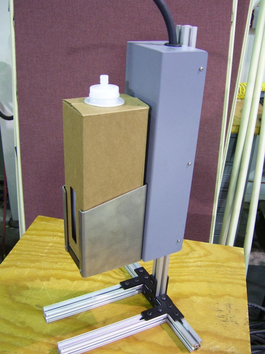
Click to zoom
Application Details
- Equipment Class
- DXX - Part 15 Low Power Communication Device Transmitter
- Date of Grant
- May 04, 2015
- Application Purpose
- Original Equipment
- Date of Application
- Apr 30, 2015
- Equipment Note
- Pumped Ink Supply
- Frequency Range
- 13.56000000 - 13.56000000
- Company
- ARRAY TECHNOLOGIES, INC.
- Country
- United States
Documents & Files
Document Text
Text extracted from the exhibit documents filed with the FCC. Open a document above to read the original.
Users Manual
Revision – PRELIMINARY Page 1 of 8 Installation Guide for Pumped Ink Supply P/N 11930-UV P/N 11930-H2O Revision – PRELIMINARY Page 2 of 8 Revision History Revision Description Date - Initial Release TBD Revision – PRELIMINARY Page 3 of 8 Notes, Cautions, and Warnings NOTE: A NOTE indicates important information about the system. CAUTION: A CAUTION indicates potential damage to hardware if instructions are not followed. WARNING: A WARNING indicates a potential for property damage, personal injury, or death. Information in this document is subject to change without notice. © Array Technologies Inc. All rights reserved. Reproduction of these materials without the written permission of Array Technologies Inc. is forbidden. Revision – PRELIMINARY Page 4 of 8 1. Unpacking/Repacking Unpack all components and verify that they match the items on the packing list. WARNING: While moving or transferring the system, it is recommended that you use the packaging material that shipped with the system and/or take care to avoid any damage due to shock or vibration. 2. Recommended Tools 1. 5/32 and 3/16 Allen Head Screwdriver or L Handle Tool 2. Introduction The Pumped Ink Supply is used with the Eagle, Osprey, and Falcon printing systems and is available as standard equipment with new systems and as a retrofit option for older systems. The ink supply is powered from the RAPTOR control box that is present in all of the printing systems, It can optionally be powered from a 24V 1A wall transformer power supply. The ink supply supports delivery of both ink and flush to the attached printer. This manual covers only the basic installation and interconnect of the Ink Supply to the printing system. WARNING: Only trained service technicians are authorized to remove the system covers and access any of the components inside the system. 3. Ink Supply Installation The RAPTOR printing system must be set up before proceeding with the ink supply installation. Locate the ink supply box and mount it in a convenient location on the transport base. The ink supply may be mounted above or below the level of the print head. The rear of the ink supply has two 1/4-20 PEM nuts for mounting the supply. Caution: Screws should not protrude more than 3/8 inch into the case when tightened. The ink supply can be attached to a standard 8020 1.0” or 1.5” extrusion using right angle brackets. Use 8020 P/N 4119-BLACK for a 1” extrusion, and 8020 P/N 4509-BLACK for the 1.5” extrusion with 1/4-20 and 5/16-18 screws as required. For a standard EAGLE or OSPREY system with a light tree, the ink supply may be mounted to the same 8020 extrusion as the light tree. Locate the ink delivery tubing assembly (unique to each type of printer) and connect one end to the ¼ turn fitting on the bottom of the ink supply and the other end to the INK IN fitting on the print head. Caution: Do not connect cables to the RAPTOR or Ink Supply with power ON. Locate the 10 foot Male to Female DB9 cable P/N 11499 and connect the male end to one of the HEAD outputs on the RAPTOR control box. Connect the female end to the DB9 connector on the bottom of the ink supply. This provides power to the ink supply from the RAPTOR control box. Alternately, any 24V to 28V 1A UL (or equivalent) listed power supply may be used if connected per the table below: DB9 Female Pin # Function 2 24V RTN (Ground) 6 24V RTN (Ground) 8 +24V 9 +24V All Other Pins No Connect Revision – PRELIMINARY Page 5 of 8 Locate the 10 foot shielded Ethernet cable P/N 10904-10 and connect it from the Ethernet jack on the bottom of the ink supply to the any open port on the Ethernet switch that is supplied with the RAPTOR printing system. Basic installation is complete at this point and the ink supply should be recognized by the RAPTOR printing system software. 4. Installing an Ink or Flush box into the ink supply Once the RAPTOR printing system software is running and the ink supply set up, an ink or flush box may be installed in the ink supply. To install the box, place the box of ink into the holder on the front of the ink supply. Press in the latch in on the fitting that is on the hose from the top of the ink supply. There should be a click and the latch should stay in place. Press the fitting on to the mating fitting on the top of the box. Press hard to insure that the seal is punctured. There will be a loud “click” when the connector is seated properly (as the latch moves back out) and it will not pull off without pressing in the latch. To remove a box, press in the latch on the fitting attached to the top of the box and pull the fitting off of the fitting on the box. Wipe the fitting from the ink supply with a KIMWIPE to clean up any ink. Note: Once the seal on the ink box is punctured, ink can spill if the box is disconnected from the ink supply and is tipped or laid on it’s side. 5. Basic Theory of Operation The Pumped Ink Supply contains the pneumatics and fluidics required to deliver ink and flush to any of the ARRAY printing systems. The ink is supplied in a bag in box format. The box has an RFID tag on the bottom that identifies the type and amount of ink in the box. Installation of an ink box into the supply is as simple as placing the box in the holder on the front of the ink supply and attaching the input connector to the fitting on the top of the ink box. Once the printing system and the ink supply are connected and turned ON and the RAPTOR software is running on the connected Windows 7 PC, the ink supply will continuously look for an RFID tag. When an ink box is installed and it’s RFID tag is read, the RFID tag on the box is compared against the type of ink required by the particular printing system and if a match, the ink supply will fill from the box (if needed) and indicate to the RAPTOR printing system that it is ready. If not a match, the ink will not be pumped from the box, an error code will be sent to the RAPTOR printing system and the status LED on the top of the ink supply will be fl…
Text truncated - open the document above for the full version.
External Photos
TUV Rheinland 710 Resende Road, Webster, NY 14580 FCC ID: 2AEF3-11930 Tel: (585) 426-0125 Report Number: 31560224.002 Ink Pump Page 1 of 3 EUT: Pumped Ink Supply Model: 11930 33_EME/I 01/29/2001 External Photos EUT Name: Pumped Ink Supply EUT Model: 11930 FCC ID: 2AEF3-11930 FCC Title 47, Part 15, SubpartC, RSS-210 Issue 8 Prepared for: David Pirie Array Technologies Inc. 21 Sequin Drive Glastonbury, CT 06033 Tel: 860-657-8086 Prepared by: TUV Rheinland of North America 710 Resende Road Webster, NY 14580 Tel: (585) 645-0125 http://www.tuv.com/ Report/Issue Date: 8 April 2015 Report Number: 31560224.002 Ink Pump TUV Rheinland 710 Resende Road, Webster, NY 14580 FCC ID: 2AEF3-11930 Tel: (585) 426-0125 Report Number: 31560224.002 Ink Pump Page 2 of 3 EUT: Pumped Ink Supply Model: 11930 33_EME/I 01/29/2001 External Photos: Figure 1: External View TUV Rheinland 710 Resende Road, Webster, NY 14580 FCC ID: 2AEF3-11930 Tel: (585) 426-0125 Report Number: 31560224.002 Ink Pump Page 3 of 3 EUT: Pumped Ink Supply Model: 11930 33_EME/I 01/29/2001 Figure 2: External View -
ID Label/Location Info
FCC ID:2AEF3-11930 Model:11930 This device complies with part 15 of the FCC rules: Operation is subject to the following two conditions: (1) This device may not cause harmful interference, and (2) This device must accept any interference received, including interference that may cause undesired operation.
Internal Photos
TUV Rheinland 710 Resende Road, Webster, NY 14580 FCC ID: 2AEF3-11930 Tel: (585) 645-0125 Report Number: 31560224.002 Ink Pump Page 1 of 2 EUT: Pumped Ink Supply Model: 11930 33_EME/I 01/29/2001 Internal Photos EUT Name: Pumped Ink Supply EUT Model: 11930 FCC ID: 2AEF3-11930 FCC Title 47, Part 15, SubpartC, RSS-210 Issue 8 Prepared for: David Pirie Array Technologies Inc. 21 Sequin Drive Glastonbury, CT 06033 Tel: 860-657-8086 Prepared by: TUV Rheinland of North America 710 Resende Road Webster, NY 14580 Tel: (585) 645-0125 http://www.tuv.com/ Report/Issue Date: 8 April 2015 Report Number: 31560224.002 Ink Pump TUV Rheinland 710 Resende Road, Webster, NY 14580 FCC ID: 2AEF3-11930 Tel: (585) 645-0125 Report Number: 31560224.002 Ink Pump Page 2 of 2 EUT: Pumped Ink Supply Model: 11930 33_EME/I 01/29/2001 Internal Photos: Figure 1: Internal View - Antenna
Internal Photos
TUV Rheinland 710 Resende Road, Webster, NY 14580 FCC ID: 2AEF3-11930 Tel: (585) 645-0125 Report Number: 31560224.002 Ink Pump Page 1 of 2 EUT: Pumped Ink Supply Model: 11930 33_EME/I 01/29/2001 Internal Photos EUT Name: Pumped Ink Supply EUT Model: 11930 FCC ID: 2AEF3-11930 FCC Title 47, Part 15, SubpartC, RSS-210 Issue 8 Prepared for: David Pirie Array Technologies Inc. 21 Sequin Drive Glastonbury, CT 06033 Tel: 860-657-8086 Prepared by: TUV Rheinland of North America 710 Resende Road Webster, NY 14580 Tel: (585) 645-0125 http://www.tuv.com/ Report/Issue Date: 8 April 2015 Report Number: 31560224.002 Ink Pump TUV Rheinland 710 Resende Road, Webster, NY 14580 FCC ID: 2AEF3-11930 Tel: (585) 645-0125 Report Number: 31560224.002 Ink Pump Page 2 of 2 EUT: Pumped Ink Supply Model: 11930 33_EME/I 01/29/2001 Internal Photos: Figure 1: Internal View - Antenna
Operational Description
Revision – PRELIMINARY Page 1 of 7 Technical Description for Pumped Ink Supply P/N 11930-UV P/N 11930-H2O Revision – PRELIMINARY Page 2 of 7 Revision History Revision Description Date - Initial Release TBD Revision – PRELIMINARY Page 3 of 7 Notes, Cautions, and Warnings NOTE: A NOTE indicates important information about the system. CAUTION: A CAUTION indicates potential damage to hardware if instructions are not followed. WARNING: A WARNING indicates a potential for property damage, personal injury, or death. Information in this document is subject to change without notice. © Array Technologies Inc. All rights reserved. Reproduction of these materials without the written permission of Array Technologies Inc. is forbidden. Revision – PRELIMINARY Page 4 of 7 1. Basic Theory of Operation The Pumped Ink Supply contains the pneumatics and fluidics required to deliver ink and flush to any of the ARRAY printing systems. The ink is supplied in a bag in box format. The box has an RFID tag on the bottom that identifies the type and amount of ink in the box. Installation of an ink box into the supply is as simple as placing the box in the holder on the front of the ink supply and attaching the input connector to the fitting on the top of the ink box. Once the printing system and the ink supply are connected and turned ON and the RAPTOR software is running on the connected Windows 7 PC, the ink supply will continuously look for an RFID tag. When an ink box is installed and it’s RFID tag is read, the RFID tag on the box is compared against the type of ink required by the particular printing system and if a match, the ink supply will fill from the box (if needed) and indicate to the RAPTOR printing system that it is ready. If not a match, the ink will not be pumped from the box, an error code will be sent to the RAPTOR printing system and the status LED on the top of the ink supply will be flashing RED. Ink is moved from the external bag/box to an internal storage tank using a liquid pump. A three way valve selects either the ink path to the tank or the flush path around the tank. The tank has a float that will turn the ink pump OFF when the fill level is reached and back ON when the tank needs to be refilled. There is always some ink in the tank, even when the float indicates that it needs to be refilled. The RAPTOR printing system controls the ink delivery to the printer by sending commands to the ink supply to start and stop the deliver operation as ink is needed by the printer. In the ink supply, delivery is performed by opening a valve at the bottom of the tank to allow ink to flow. An air pump system will then pressurize the tank to force the ink to the printing system. Pressure is programmable and is set for the type of printing system being used. The internal tank may be automatically refilled from the ink box while delivery is in process. If a flush box is installed, the 3 way valve at the top of the tank is turned ON and the valve at the bottom of the tank is turned OFF. This routes the flush around the ink tank (preventing ink and flush from mixing in the tank) to minimize the amount of ink needed to refill the system after a flush. When commanded by the RAPTOR printing system, the ink supply will use the liquid pump to directly move the flush from the bag/box to the ink supply output and to the printer. The ink pump has a check valve in parallel (from input to output) that will turn ON if pressure exceeds 10psi, preventing the ink pump from over pressuring the line if there is a valve failure or blockage in the printer. During operation, the ink supply will track ink usage (flush is not tracked) and periodically update the RFID tag on the box with the amount of ink used until the box is empty. At that time the RFID tag on the box will be marked as empty so that the box can not be refilled. The RAPTOR printing system will display a gauge showing the ink usage and the ink supply status. 2. Operational Description of Transmitter The transmitter is composed of a TI TRF7960 RFID chip. The TRF7960/61 is an integrated analog front end and data-framing system for a 13.56-MHz RFID reader system. The RF interface is conditioned by an impedance matching network, and transmitted through a 4”long SMA cable to and Antenna PN 119321- 01. The transmitter has selectable output power levels of 100 mW (20 dBm) or 200 mW (23 dBm) into a 50-Ω load (5 -V supply) and is capable of ASK or OOK modulation. Data transmission comprises low-level encoding for ISO15693, modified Miller for ISO14443-A, high-bit-rate systems for ISO14443 and Tag-it coding systems. Included with the data encoding is automatic generation of SOF, EOF, CRC, and / or parity bits. The receiver system enables AM and PM demodulation using a dual-input architecture. The receiver also includes an automatic gain control option and selectable gain. Also included is a selectable bandwidth to cover a broad range of input sub-carrier signal options. The received signal strength for AM and PM Revision – PRELIMINARY Page 5 of 7 modulation is accessible via the RSSI register. The receiver output is a digitized sub-carrier signal among a selectable protocol and bit rate. A selected decoder delivers bit stream and a data clock as outputs. The receiver system also includes a framing system. This system performs CRC and / or parity check, removes the EOF and SOF settings, and organizes the data in bytes. Framed data is then accessible to the MCU via a 12-byte FIFO register and MCU interface. The framing supports ISO14443 and ISO15693 protocols. This complete subsystem provides for bidirectional communications with the passive RFID Tag attached to the underside of the Ink Box which contains information about the ink contained in the bottle so that the pumping system may be appropriately configured. 3. Technical Specifications Power Unit Voltage Current Ink Supply (11930) 24VDC to 28VDC 600mA Physical Unit Height Width Depth Weight Ink Supply (11930) 14.50 (36.…
Text truncated - open the document above for the full version.
Test Report
FCC ID: 2AEF3-11930 Report No.: 31560224.005 Ink Pump.doc Page 1 of 35 The test results contained in this report refer exclusively to the product(s) presented for testing. No liability may be assumed for models or products not referred to herein. This test report may not be published or duplicated in part without permission of the testing body. This test report by itself does not constitute authorization for the use of any TUV Rheinland test mark. The report must not be used by the client to claim product certification, approval, or endorsement by A2LA or any agency of the Federal Government. TUV Rheinland of North America, Inc., 710 Resende Road, Webster NY 14580. Tel: 585-645-0125 MS-0005239 Version 3.0 Electromagnetic Compatibility Test Report Prepared in accordance with FCC Part 15C, RSS-210 Issue 8 and ANSI C63.10 C63.10:2009 and C63.10:2013 Versions were both used On Pumped Ink Supply 11930 ARRAY TECHNOLOGIES INC. 21 Sequin Dr Glastonbury CT, 06033 Prepared by: TUV Rheinland of North America, Inc. FCC ID: 2AEF3-11930 Report No.: 31560224.005 Ink Pump.doc Page 3 of 35 The test results contained in this report refer exclusively to the product(s) presented for testing. No liability may be assumed for models or products not referred to herein. This test report may not be published or duplicated in part without permission of the testing body. This test report by itself does not constitute authorization for the use of any TUV Rheinland test mark. The report must not be used by the client to claim product certification, approval, or endorsement by A2LA or any agency of the Federal Government. TUV Rheinland of North America, Inc., 710 Resende Road, Webster NY 14580. Tel: 585-645-0125 MS-0005239 Version 3.0 Client: ARRAY TECHNOLOGIES INC. 21 Sequin Dr Glastonbury CT, 06033 Contact: Tel: Fax: e-mail David Pirie 860-657-8086 [email protected] Identification: Pumped Ink Supply Serial No.: TS-1 Test item: Model 11930 Date Test Completed: 3/23/2015 Testing location: TUV Rheinland of North America 710 Resende Road Webster, NY 14580 U.S.A. Tel: (585) 645-0125 Test specification: Emissions: FCC Part 15.225Radiated Emissions Std FCC Part 15.209 and RSS - 210 Issue 8, FCC Part 15.225(b) and RSS - 210 Issue 8, FCC Part 15.203 Test Result: The above product was found to be Compliant to the above test standard(s) tested by: Randall Masline reviewed by: Cecil Gittens 1 May 2015 Date Name Signature 1 May 2015 Date Name Signature Other Aspects: None Abbreviations: OK, Pass, Compliant, Complies = passed Fail, Not Compliant, Does Not Comply = failed N/A = not applicable Industry Canada VCCI BSMI US5253 Testing Cert.# 3331.08 482B-1 A-0203 SL2-IN-E- 050R FCC ID: 2AEF3-11930 Report No.: 31560224.005 Ink Pump.doc Page 4 of 35 The test results contained in this report refer exclusively to the product(s) presented for testing. No liability may be assumed for models or products not referred to herein. This test report may not be published or duplicated in part without permission of the testing body. This test report by itself does not constitute authorization for the use of any TUV Rheinland test mark. The report must not be used by the client to claim product certification, approval, or endorsement by A2LA or any agency of the Federal Government. TUV Rheinland of North America, Inc., 710 Resende Road, Webster NY 14580. Tel: 585-645-0125 MS-0005239 Version 3.0 TABLE OF CONTENTS 1 GENERAL INFORMATION ......................................................................................................................... 5 1.1 SCOPE ......................................................................................................................................................... 5 1.2 PURPOSE ..................................................................................................................................................... 5 1.3 SUMMARY OF TEST RESULTS ..................................................................................................................... 6 2 LABORATORY INFORMATION ................................................................................................................ 7 2.1 ACCREDITATIONS & ENDORSEMENTS ........................................................................................................ 7 2.2 MEASUREMENT UNCERTAINTY EMISSIONS ............................................................................................... 8 2.3 CALIBRATION TRACEABILITY .................................................................................................................... 8 2.4 MEASUREMENT EQUIPMENT USED ............................................................................................................ 9 3 PRODUCT INFORMATION ....................................................................................................................... 10 3.1 EQUIPMENT MODIFICATIONS ................................................................................................................... 10 3.2 TEST PLAN ................................................................................................................................................ 10 4 EMISSIONS .................................................................................................................................................... 11 4.1 RADIATED EMISSIONS .............................................................................................................................. 11 4.2 FUNDAMENTAL FIELD STRENGTH AND HARMONIC EMISSIONS .............................................................. 14 4.3 CONDUCTED EMISSIONS ........................................................................................................................... 22 4.1 FREQUENCY TOLERANCE ......................................................................................................................... 28 4.1 BANDWIDTH .............................................…
Text truncated - open the document above for the full version.
Test Setup Photos
TUV Rheinland 710 Resende Road, Webster, NY 14580 FCC ID: 2AEF3-11930 Tel: (585) 645-0125 Report Number: 31560224.002 Ink Pump Page 1 of 3 EUT: Pumped Ink Supply Model: 11930 33_EME/I 01/29/2001 Test Setup Photos EUT Name: Pumped Ink Supply EUT Model: 11930 FCC ID: 2AEF3-11930 FCC Title 47, Part 15, SubpartC, RSS-210 Issue 8 Prepared for: David Pirie Array Technologies Inc. 21 Sequin Drive Glastonbury, CT 06033 Tel: 860-657-8086 Prepared by: TUV Rheinland of North America 710 Resende Road Webster, NY 14580 Tel: (585) 645-0125 http://www.tuv.com/ Report/Issue Date: 8 April 2015 Report Number: 31560224.002 Ink Pump TUV Rheinland 710 Resende Road, Webster, NY 14580 FCC ID: 2AEF3-11930 Tel: (585) 645-0125 Report Number: 31560224.002 Ink Pump Page 2 of 3 EUT: Pumped Ink Supply Model: 11930 33_EME/I 01/29/2001 Test Setup Photos: Figure 1: Test Setup – Field Strength Figure 2: Test Setup – Field Strength TUV Rheinland 710 Resende Road, Webster, NY 14580 FCC ID: 2AEF3-11930 Tel: (585) 645-0125 Report Number: 31560224.002 Ink Pump Page 3 of 3 EUT: Pumped Ink Supply Model: 11930 33_EME/I 01/29/2001 Figure 3: Test Setup – Conducted Emissions Figure 4: Test Setup – Radiated Emissions
Contact Information
Applicant
DAVID PIRIE(PRESIDENT)
Test Firm
TUV Rheinland of North AmericaDavid Lanski
[email protected](585) 357-6044
Technical Specifications
| # | Rule Parts | Frequency Range | Power Output | Emission |
|---|---|---|---|---|
| 1 | 15C | 13.56 MHz - 13.56 MHz | 100.00 µW | A1D |