2AEHH-B18PACE 2
Coros Wearables Inc.
Click to zoom
Application Details
- Equipment Class
- DTS - Digital Transmission System
- Date of Grant
- Aug 30, 2020
- Application Purpose
- Original Equipment
- Date of Application
- Aug 29, 2020
- Equipment Note
- PACE 2
- Frequency Range
- 2457.00000000 - 2457.00000000
- Company
- Coros Wearables Inc.
- Country
- United States
Documents & Files
Document Text
Text extracted from the exhibit documents filed with the FCC. Open a document above to read the original.
Users Manual
COROS WEARABLES INC. Address: 14511 Franklin Ave. Suite 220 Tustin, CA 92780, USA Email: [email protected] Website: www.coros.com Follow us @COROSGlobal PRODUCT SAFETY & WARRANTY POLICY English 简体中文 繁體中文 Deutsch Français Italiano Español Indonesia 01 15 23 31 45 59 73 87 101 01- EnglishEnglish- 02 By using any one of the outdoor activity profiles (i.e. swim, cycle, run), you are activating the GPS automatically. If GPS is being used to calibrate altitude, the margin of error is within approximately 165ft. For best results, avoid locations with signal interference and allow GPS to locate your position prior to starting an activity. Note: GPS signal will be lost if the COROS device is submerged underwater. For open water swimming, it is recommended to use freestyle strokes for better GPS accuracy. The COROS watch uses an optical heart rate monitor, that flashes a green LED light onto the wrist to measure heart rate. To improve accuracy of the heart rate monitor, please fasten your watch band and make sure the watch rests securely on your wrist. Note: The heart rate monitor is not for medical use and may be subject to external interference. Always consult your physician before starting an exercise program. Heart rate data is for reference only and COROS shall not be held responsible for the consequences of any readings. Note: Using navigation will automatically turn on the GPS. Please use your best judgement during navigation. If your COROS device supports navigation functionality, you may pre-load the route to the device as a .GPX file from the COROS App. If your COROS device supports mapping functionality, you may access it from the main menu under Maps. Note: COROS uses a third-party provider for map data information. Please read the terms and conditions of the provider before downloading and using the mapping function. COROS is not responsible for the accuracy of the data and the stability of the connection. The optical oximeter sensor flashes an infrared light onto the wrist to determine the user’s blood oxygen level. In order to ensure the accuracy of the oximeter sensor, please fasten your watch band and make sure the watch fits securely against your wrist. The optical oximeter is available on select COROS watch models. To see a complete list of compatible models, please visit www.coros.com. Note: The oximeter sensor is not for medical use and may be subject to external interference. Certain circumstances may cause the blood oxygen reading to be inaccurate. Blood oxygen readings are for reference only and COROS shall not be held responsible for the consequences of any readings. GPS Wearing the Device and Heart Rate Navigation Maps (Available on select models) Oximeter (Available on select models) 03- EnglishEnglish- 04 The COROS device supports many wireless ANT+ and Bluetooth Smart sensors. The first time you connect an ANT+ or Bluetooth Smart enabled sensor to the COROS device, navigate to Menu > Settings > Accessories > Add ANT+ or Add Bluetooth to complete the pairing process. The COROS device is equipped with a geomagnetic sensor, thermometer, barometer, gyroscope, and accelerometer. An accelerometer is used for detecting hand gestures, steps and the calculation of Caloric data. The compass uses a geomagnetic sensor to show directions. Both the thermometer and barometer will detect ambient temperature and atmospheric pressure. Note: The data captured by these sensors may not be completely accurate and is for reference only. It is recommended you thoroughly clean your COROS device to remove excess sweat and debris after frequent usage. If not properly cleaned, residual sweat may corrode the device. To properly clean the device, please use mild soapy water and ensure the device remains dry when contacting the skin. If skin irritation occurs, remove the device immediately. Keep the heart rate monitor sensor and charging port clean and clear of debris (i.e. sand, sweat, dirt, etc.). Avoid excessive exposure to extreme hot or cold temperatures. The COROS device comes with a USB charging cable and a watch band. Please remove and clean the watch band regularly to avoid skin irritation. The watch band is not covered under warranty policy. Note: Please only use the COROS charging cable and watch band. The COROS watch contains a Bluetooth module for smartphone and external sensor connection. The Bluetooth module uses a 2.4 GHz frequency and may interfere with inflight and ground communication devices. Battery Warnings Do not perform unauthorized battery replacement. Avoid excessive exposure to extreme hot or cold temperatures. Do not submerge the battery. Keep the battery away from children. Data Security Accidental damages and improper operation may cause daily and workout data loss. Please sync the COROS device with the COROS App regularly. Product repair may cause data loss. Privacy You can find detailed Privacy Policy and Terms of Service in the COROS App on the About Us page. Bluetooth Daily Maintenance Accessories Safety Warnings External Sensors (Available on select models) Sensors 05- EnglishEnglish- 06 Toxic Materials (Pb)(Hg)(Cd)(Cr(VI))(PBB)(PBDE) X O X O O O O O O O O O O O O O O O O O O O O O Component Components in the watch body Wrist Band Battery Charging Cable COROS will help replace your product or remedy your issue. Simply reach out to us via phone or e-mail to assist in completing a warranty claim and our team will handle your claim in a timely fashion. United States & Canada Phone: 714-389-0269 (9am-6pm PST, M-F) E-mail: [email protected] Should you need support outside the United States & Canada, please reach out to the contacts above and we’ ll direct you to the best local support. COROS Wearables Inc. ("COROS") warrants that the Product (defined below) delivered hereunder to the original purchaser ("Original Purchaser") from COROS.com or a COROS Authorized Reseller (each an "Authorized Reseller") will be free from material and workmanship defects that adversely affect…
Text truncated - open the document above for the full version.
External Photos
Test model number: B18
Internal Photos
Test model number: B18
RF Exposure Info
FCC ID: 2AEHH-B18 RF Exposure Evaluation According to KDB 447498 and part 2.1093,Unless specifically required by the published RF exposure KDB procedures, standalone 1-g head or body and 10-g extremity SAR evaluation for general population exposure conditions, by measurement or numerical simulation, is not required when the corresponding SAR Test Exclusion Threshold condition(s), listed below, is (are) satisfied. For 100 MHz to 6 GHz and test separation distances ≤ 50 mm, the 1-g and 10-g SAR test exclusion thresholds are determined by the following: [(max. power of channel, including tune-up tolerance, mW) / (min. test separation distance, mm)] · [√f (GHz) ] ≤ 3.0 for 1-g SAR, and ≤ 7.5 for 10-g extremity SAR, where f (GHz) is the RF channel transmit frequency in GHz Power and distance are rounded to the nearest mW and mm before calculation The result is rounded to one decimal place for comparison Here, For BLE Max Power(dBm) Max Power(mW) Frequency(MHz) Min. distance(mm) Calc. thresholds limit -0.25 0.94 2402 5 0.291 3.0 For ANT+ Max Power(dBm) Max Power(mW) Frequency(MHz) Min. distance(mm) Calc. thresholds limit -0.29 0.94 2457 5 0.295 3.0 Remark: antenna gain=-6.01dBi So a SAR test is not required
Test Report
Global United Technology Services Co., Ltd. Report No.: GTS202004000150F01 Authorized Signature: Robinson Lo Laboratory Manager This results shown in this test report refer only to the sample(s) tested, this test report cannot be reproduced, except in full, without prior written permission of the company. The report would be invalid without specific stamp of test institute and the signatures of compiler and approver. Page 1 of 34 TEST REPORT Applicant: Coros Wearables Inc. Address of Applicant: 14511 FRANKLIN AVENUE SUITE 220, TUSTIN, CA 92780, United States Manufacturer/Factory: Guangdong COROS Sports Technology Co.,Ltd Address of Manufacturer/Factory: No. 18, Gongyedong Road, Songshan Lake Hi-Tech Industrial Park, Dongguan, Guangdong Province, 523808, China Equipment Under Test (EUT) Product Name: PACE 2 Model No.: B18 Trade Mark: COROS FCC ID: 2AEHH-B18 Applicable standards: FCC CFR Title 47 Part 15 Subpart C Section 15.247 Date of sample receipt: April 22, 2020 Date of Test: April 22-26, 2020 Date of report issued: April 26, 2020 Test Result : PASS * * In the configuration tested, the EUT complied with the standards specified above. Report No.: GTS202004000150F01 Global United Technology Services Co., Ltd. No. 123- 128, Tower A, Jinyuan Business Building, No.2, Laodong Industrial Zone, Xixiang Road, Baoan District, Shenzhen, Guangdong, China 518102 Telephone: +86 (0) 755 2779 8480 Fax: +86 (0) 755 2779 8960 Page 2 of 34 2 Version Version No. Date Description 00 April 26, 2020 Original Prepared By: Date: April 26, 2020 Project Engineer Check By: Date: April 26, 2020 Reviewer Report No.: GTS202004000150F01 Global United Technology Services Co., Ltd. No. 123- 128, Tower A, Jinyuan Business Building, No.2, Laodong Industrial Zone, Xixiang Road, Baoan District, Shenzhen, Guangdong, China 518102 Telephone: +86 (0) 755 2779 8480 Fax: +86 (0) 755 2779 8960 Page 3 of 34 3 Contents Page 1 COVER PAGE ........................................................................................................................................... 1 2 VERSION .................................................................................................................................................. 2 3 CONTENTS .............................................................................................................................................. 3 4 TEST SUMMARY ..................................................................................................................................... 4 5 GENERAL INFORMATION ...................................................................................................................... 5 5.1 GENERAL DESCRIPTION OF EUT ......................................................................................................... 5 5.2 TEST MODE ........................................................................................................................................ 7 5.3 DESCRIPTION OF SUPPORT UNITS ....................................................................................................... 7 5.4 DEVIATION FROM STANDARDS ............................................................................................................. 7 5.5 ABNORMALITIES FROM STANDARD CONDITIONS ................................................................................... 7 5.6 TEST FACILITY .................................................................................................................................... 7 5.7 TEST LOCATION ................................................................................................................................. 7 5.8 ADDITIONAL INSTRUCTIONS ................................................................................................................. 7 6 TEST INSTRUMENTS LIST ..................................................................................................................... 8 7 TEST RESULTS AND MEASUREMENT DATA .................................................................................... 10 7.1 ANTENNA REQUIREMENT ................................................................................................................... 10 7.2 CONDUCTED EMISSIONS ................................................................................................................... 11 7.3 CONDUCTED OUTPUT POWER ........................................................................................................... 14 7.4 CHANNEL BANDWIDTH ...................................................................................................................... 16 7.5 POWER SPECTRAL DENSITY ............................................................................................................. 18 7.6 BAND EDGES .................................................................................................................................... 20 7.6.1 Conducted Emission Method ..................................................................................................... 20 7.6.2 Radiated Emission Method ........................................................................................................ 21 7.7 SPURIOUS EMISSION ......................................................................................................................... 24 7.7.1 Conducted Emission Method ..................................................................................................... 24 7.7.2 Radiated Emission Method ........................................................................................................ 26 8 TEST SETUP PHOTO ............................................................................................................................ 34 9 EUT CONSTRUCTIONAL DETAILS ..................................................................................................... 34 Report No.: GTS202004000150F01 Global United Technology Services Co…
Text truncated - open the document above for the full version.
Test Report
Global United Technology Services Co., Ltd. Report No.: GTS202004000150F02 Authorized Signature: Robinson Lo Laboratory Manager This results shown in this test report refer only to the sample(s) tested, this test report cannot be reproduced, except in full, without prior written permission of the company. The report would be invalid without specific stamp of test institute and the signatures of compiler and approver. Page 1 of 27 TEST REPORT Applicant: Coros Wearables Inc. Address of Applicant: 14511 FRANKLIN AVENUE SUITE 220, TUSTIN, CA 92780, United States Manufacturer/Factory: Guangdong COROS Sports Technology Co.,Ltd Address of Manufacturer/Factory: No. 18, Gongyedong Road, Songshan Lake Hi-Tech Industrial Park, Dongguan, Guangdong Province, 523808, China Equipment Under Test (EUT) Product Name: PACE 2 Model No.: B18 Trade Mark: COROS FCC ID: 2AEHH-B18 Applicable standards: FCC CFR Title 47 Part 15 Subpart C Section 15.247 Date of sample receipt: April 22, 2020 Date of Test: April 22-26, 2020 Date of report issued: April 26, 2020 Test Result : PASS * * In the configuration tested, the EUT complied with the standards specified above. Report No.: GTS202004000150F02 Global United Technology Services Co., Ltd. No. 123- 128, Tower A, Jinyuan Business Building, No.2, Laodong Industrial Zone, Xixiang Road, Baoan District, Shenzhen, Guangdong, China 518102 Telephone: +86 (0) 755 2779 8480 Fax: +86 (0) 755 2779 8960 Page 2 of 27 2 Version Version No. Date Description 00 April 26, 2020 Original Prepared By: Date: April 26, 2020 Project Engineer Check By: Date: April 26, 2020 Reviewer Report No.: GTS202004000150F02 Global United Technology Services Co., Ltd. No. 123- 128, Tower A, Jinyuan Business Building, No.2, Laodong Industrial Zone, Xixiang Road, Baoan District, Shenzhen, Guangdong, China 518102 Telephone: +86 (0) 755 2779 8480 Fax: +86 (0) 755 2779 8960 Page 3 of 27 3 Contents Page 1 COVER PAGE ........................................................................................................................................... 1 2 VERSION .................................................................................................................................................. 2 3 CONTENTS .............................................................................................................................................. 3 4 TEST SUMMARY ..................................................................................................................................... 4 5 GENERAL INFORMATION ...................................................................................................................... 5 5.1 GENERAL DESCRIPTION OF EUT ......................................................................................................... 5 5.2 TEST MODE ........................................................................................................................................ 6 5.3 DESCRIPTION OF SUPPORT UNITS ....................................................................................................... 6 5.4 DEVIATION FROM STANDARDS ............................................................................................................. 6 5.5 ABNORMALITIES FROM STANDARD CONDITIONS ................................................................................... 6 5.6 TEST FACILITY .................................................................................................................................... 6 5.7 TEST LOCATION ................................................................................................................................. 6 5.8 ADDITIONAL INSTRUCTIONS ................................................................................................................. 6 6 TEST INSTRUMENTS LIST ..................................................................................................................... 7 7 TEST RESULTS AND MEASUREMENT DATA ...................................................................................... 9 7.1 ANTENNA REQUIREMENT ..................................................................................................................... 9 7.2 CONDUCTED EMISSIONS ................................................................................................................... 10 7.3 CONDUCTED OUTPUT POWER ........................................................................................................... 13 7.4 CHANNEL BANDWIDTH ...................................................................................................................... 14 7.5 POWER SPECTRAL DENSITY ............................................................................................................. 15 7.6 BAND EDGES .................................................................................................................................... 16 7.6.1 Conducted Emission Method ..................................................................................................... 16 7.6.2 Radiated Emission Method ........................................................................................................ 17 7.7 SPURIOUS EMISSION ......................................................................................................................... 19 7.7.1 Conducted Emission Method ..................................................................................................... 19 7.7.2 Radiated Emission Method ........................................................................................................ 21 8 TEST SETUP PHOTO ............................................................................................................................ 27 9 EUT CONSTRUCTIONAL DETAILS ..................................................................................................... 27 Report No.: GTS202004000150F02 Global United Technology Services …
Text truncated - open the document above for the full version.
Test Setup Photos
Test model number: B18 Radiated Emission Conducted Emission
Contact Information
Applicant
Qiang Wu(Quality Director)
Test Firm
Global United Technology Services Co. Ltd.Robinson Lo
Technical Specifications
| # | Rule Parts | Frequency Range | Power Output |
|---|---|---|---|
| 2 | 15C | 2.46 GHz - 2.46 GHz | 935.00 µW |
Other Applications from Coros Wearables Inc.
2AEHH-FD05B
Apr 10, 2024COROS POD 2
Equipment Class
DTS - Digital Transmission System2AEHH-W521B
Jan 21, 2024COROS APEX 2 Pro
Equipment Class
DSS - Part 15 Spread Spectrum Transmitter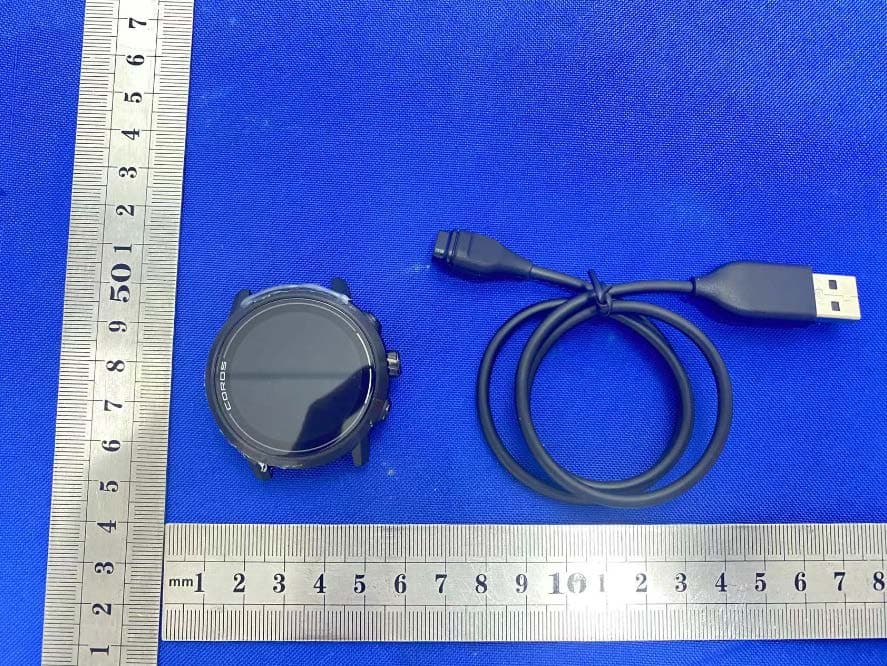
2AEHH-W522
Nov 06, 2022APEX 2
Equipment Class
DSS - Part 15 Spread Spectrum Transmitter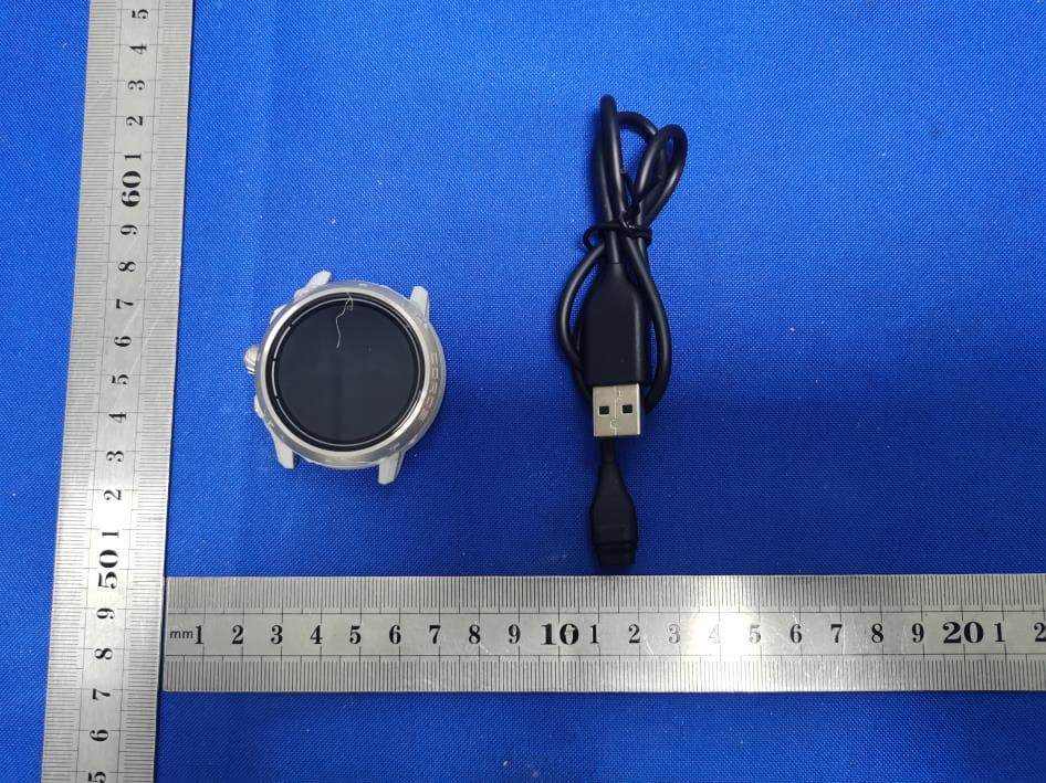
2AEHH-W521
Nov 06, 2022APEX 2 Pro
Equipment Class
DSS - Part 15 Spread Spectrum Transmitter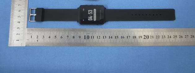
2AEHH-CB08
Apr 18, 2015Smart Watch
Equipment Class
DSS - Part 15 Spread Spectrum Transmitter