2AES2-1465Model 1465 UHF Multi-Carrier In-Building Amplifier
Applied Micro Design, Inc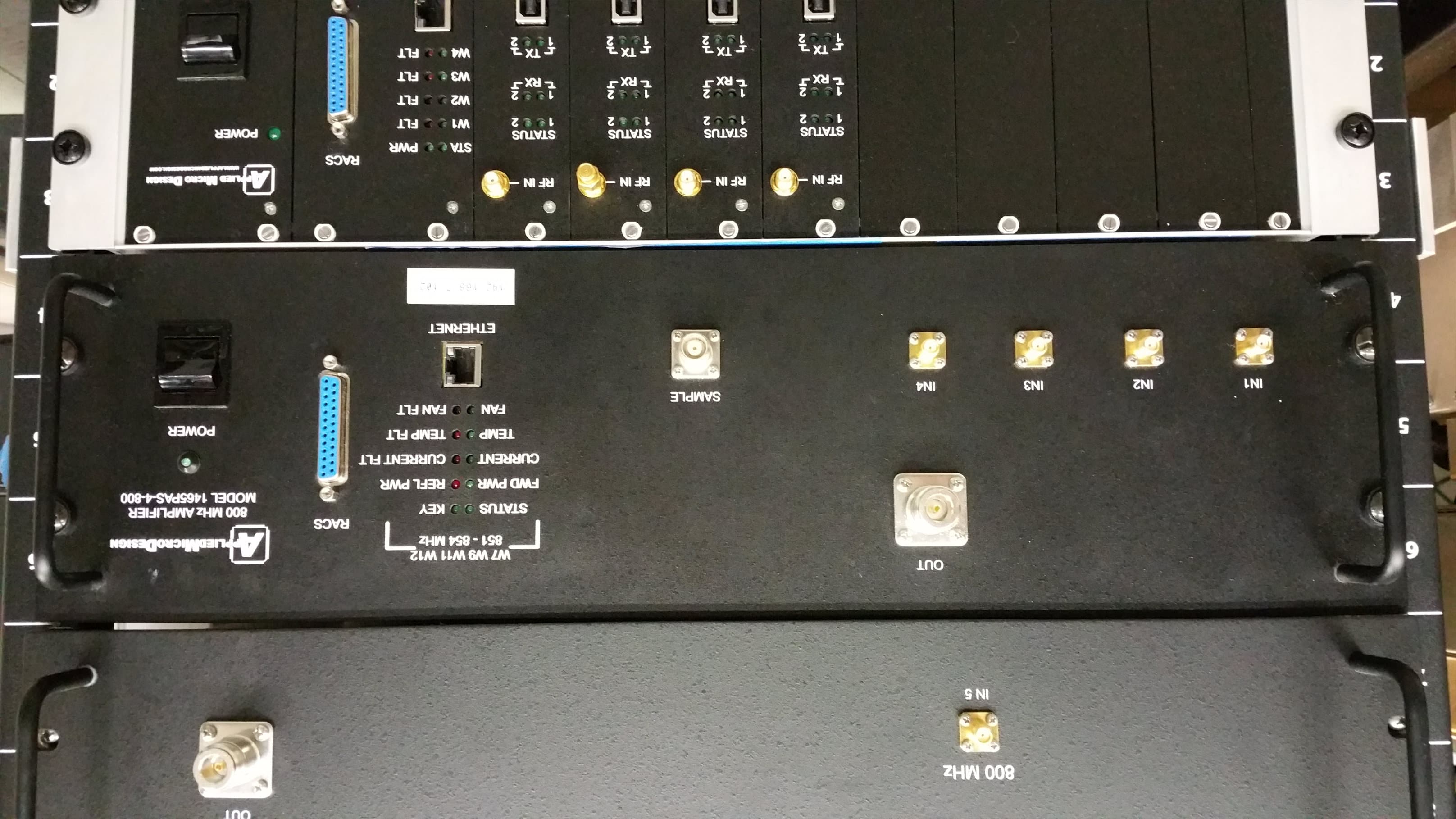
Click to zoom
Application Details
- Equipment Class
- B9B - Part 90 Class B Industrial Booster (non-SMR)
- Date of Grant
- Sep 27, 2015
- Application Purpose
- Original Equipment
- Date of Application
- Aug 20, 2015
- Equipment Note
- Model 1465 UHF Multi-Carrier In-Building Amplifier
- Frequency Range
- 851.07500000 - 853.35000000
- Company
- Applied Micro Design, Inc
- Country
- United States
Documents & Files
Document Text
Text extracted from the exhibit documents filed with the FCC. Open a document above to read the original.
Users Manual
WTC4 Head End System Channelized Bi-Directional Amplifier User’s Manual rev 6 19516 Amaranth Drive Germantown MD 20874 ph 301.540.9506 | [email protected] | www.appliedmicrodesign.com A p p l i e d M i c r o D e s i g n I n c . Table of Contents Notes, Cautions, and Warnings System Description System Block Diagram Downlink Rack Uplink Rack DSP Card Cage DSP Front Panels & Indicators DSP Description & Specifications Dual Power Amplifier Front Panel & Indicators Single Power Amplifier Front Panel & Indicators Power Amplifier Description & Specifications CBC/Combiner Front Panel CBC/Combiner Description & Specifications CBC/Splitter Front Panel & Indicators CBC/Splitter Description & Specifications Downlink Rack RF Cable Interconnection Uplink Rack RF Cable Interconnection Downlink Rack Ethernet Cable Interconnection Uplink Rack Ethernet Cable Interconnection Downlink Cabinet RF Cables Uplink Cabinet RF Cables Downlink Installation Uplink Installation Appendix A - NMS GUI Manual Appendix B - RACS (Radio Access Control System) Description Appendix C - DSP User GUI Operation Part 90 (Class B) Signal Boosters WARNING. This is NOT a CONSUMER device. It is designed for installation by FCC LICENSEES and QUALIFIED INSTALLERS. You MUST have an FCC LICENSE or express consent of an FCC Licensee to operate this device. You MUST register Class B signal boosters (as defined in 47 CFR 90.219) online at www.fcc.gov/signal-booster/registration. Unauthorized use may result in significant forfeiture penalties, including penalties in excess of $100,000 for each continuing violation. This is a Class B Booster. Notes, Cautions, and Warnings ! Connect RF Output to existing Distributed Antenna System (DAS) cable only. DO NOT operate equipment with unauthorized antennas, cables, and/or coupling devices. DO NOT operate equipment unless all RF connectors are secure. DO NOT operate equipment unless it has been installed and inspected by a qualified radio technician. Contact Information For more information contact the FCC at: https://signalboosters.fcc.gov/signal-boosters/ F.2 PART 90 CLASS B SIGNAL BOOSTERS Licensees and signal booster operators are required to register existing Class B signal booster installations with the FCC by November 1, 2014. After November 1, 2014, operation of an existing, unregistered Class B signal booster will be unauthorized and subject to enforcement action. Any new Class B signal booster installed after November 1, 2014 must be registered prior to operation. To encourage compliance with this new requirement, registration will be free of cost to the operator and/or licensee.[R11], [R9] FCC Part 90 Class B Signal Booster Registration & Discovery website: https://signalboosters.fcc.gov/signal-boosters/ Introduction There are three major components to the Tower-4 system; the Head-End hardware, the Distributed Antenna System (DAS) hardware, and the Site-Wide Network (SWN). Signals from the SWN are input to the Downlink (DL) Head-End (HE) hardware. These signals are filtered and amplified by the HE DL, and fed into the DAS. Signals from the DAS are input to the Uplink (UL) HE hardware. These signals are filtered and amplified by the HE UL, and fed into the SWN. There are two equipment rooms in Tower-4, and each equipment room has an Uplink and Downlink rack. One each of these racks (one UL and one DL) will be tested. The Downlink Rack contains three DSP Card Cages, two Dual Amplifiers, one Single Amplifier, and one CBC chassis. The signals are combined in the CBC chassis and fed to the DAS. The Uplink Rack contains three DSP Card Cages and one CBC chassis. Signals from the DAS are input to the CBC chassis. The UL and DL Channel Cards are the same design. They are FPGA-based designs, programmed essentially as active digital filters. The cards have a standard line-up; Analog-to-Digital Conversion, Digital Demodulation to baseband, digital filtering in the FPGA, Digital Modulation back to the original carrier frequency, and Digital-to-Analog conversion. The DSP Channel Cards can be programmed for multiple filters to process multi-carrier signals. Head-End Downlink Group There are eleven SWN windows (seven 400 MHz and four 800 MHz) input to the HE channel cards. Each window is input to a separate card; each card is set for one wide-band filter to pass multi-carrier signals, and is set for a specified gain. Wide-band filters for the DL are specified to achieve the required Group or Propagation Delay of 10 μs. The Site Wide Network (SDN Demarc) provides a constant level of -10 dBm per carrier into each Downlink Channel Card. The outputs of the Downlink Channel Cards are input to power amplifiers, either directly or via a combiner. Window groupings to the power amplifiers are shown on the system block diagrams. The gain of the Downlink Channel Cards are set to have an output of +20 dBm per carrier (100 mW) at the output of the power amplifiers, with -10 dBm per carrier at the input of the Downlink Channel Cards. The 800 MHz Downlink Channel Cards are set to have an output of +22 dBm at the output of the power amplifiers. The power amplifiers are very linear and can handle multiple carriers. The ALC (Automatic Level Control) of each amplifier is set to provide a maximum of +37 dBm (5W). The outputs of the 400 MHz and 800 MHz power amplifiers are combined through combiners and low-loss CBC (Cross- Band Couplers). The output of the CBC is the connection into the DAS. Head-End Uplink Group There are eleven windows (seven 400 MHz and four 800 MHz) input to the UL channel cards from the DAS. Each window is input to a separate card; each card is set for one or more narrow-band filter to pass multi-carrier signals. Narrow-band filters for the UL are specified to achieve the required Group or Propagation Delay of 25 μs. A group of frequencies (window grouping) is assigned to one Uplink Channel Card. The signals coming from the DAS are amplified with an LNA (low-noise amplifier) and distributed to …
Text truncated - open the document above for the full version.
Attestation Statements
19516 Amaranth Drive, Germantown, Maryland • Tel: (301) 540-9506 • Fax: (301) 540-8937 A PPLIED ICRO ESIGNMD Attestation Letter Date: July 1, 2015 American Certification Body, Inc. 6731 Whittier Avenue Suite C110 McLean, VA 22101 To Whom It May Concern: I, Stanley Mantel, hereby attest that the warning label below will be (a) permanently attached to the front panel of each device, (b) shown on-line with any related marketing materials, and (c) included on any hard-copy marketing materials. This is being done in accordance with KDB 935210 D02. By: Stanley Mantel (Signature) (Print name) Title: President On behalf of: Applied Micro Design, Inc. (Company Name) Telephone: 301-540-9506
Block Diagram
WTC4 HE Alarms Diagram rev 3 Downlink Group PROPRIETARY This document is issued in strict confidence on condition that it is not copied, reprinted, or disclosed to a third party, wholly or in part, without written consent of Applied Micro Design, Incorporated. Window 7 Window 9 Window 11 Window 12 Power Amplifier Enable/Disable Forward Pwr Reverse Pwr ALC ALC Level Power Supply Current Sense Analog Interface Serial Interface Digital Interface Processor Ethernet Interface Status Key Fwd Pwr Ref Pwr Current Current Fault Temperature Temp Fault Fan Fault Fan RACS NC NC NO NO NC NC NO NO Temperature Fan Fault T Amplifier Processor Analog Interface Serial Interface Digital Interface Processor Ethernet Interface RACS NC NC NO NO NC NC NO NO Power Amplifier Enable/Disable Forward Pwr Reverse Pwr ALC ALC Level Power Supply Current Sense Analog Interface Serial Interface Digital Interface Processor Ethernet Interface Status Key Fwd Pwr Ref Pwr Current Current Fault Temperature Temp Fault Fan Fault Fan RACS NC NC NO NO NC NC NO NO Temperature Fan Fault T Amplifier Processor Enable/Disable Forward Pwr Reverse Pwr ALC ALC Level Power Supply Current Sense Analog Interface Serial Interface Digital Interface Processor Ethernet Interface Status Key Fwd Pwr Ref Pwr Current Current Fault Temperature Temp Fault Fan Fault Fan RACS NC NC NO NO NC NC NO NO Temperature Fan Fault T Amplifier Processor Enable/Disable Forward Pwr Reverse Pwr ALC ALC Level Power Supply Current Sense Analog Interface Serial Interface Digital Interface Processor Ethernet Interface Status Key Fwd Pwr Ref Pwr Current Current Fault Temperature Temp Fault Fan Fault Fan RACS NC NC NO NO NC NC NO NO Temperature Fan Fault T Amplifier Processor Power Amplifier Enable/Disable Forward Pwr Reverse Pwr ALC ALC Level Power Supply Current Sense Analog Interface Serial Interface Digital Interface Processor Ethernet Interface Status Key Fwd Pwr Ref Pwr Current Current Fault Temperature Temp Fault Fan Fault Fan RACS NC NC NO NO NC NC NO NO Temperature Fan Fault T Amplifier Processor Window 1 Window 2 Window 3 Window 4 Analog Interface Serial Interface Digital Interface Processor Ethernet Interface RACS NC NC NO NO NC NC NO NO Channel Card Processor Window 8 Window 6 Window 10 Analog Interface Serial Interface Digital Interface Processor Ethernet Interface RACS NC NC NO NO NC NC NO NO Channel Card Processor Channel Card Processor to Ethernet switch (MCAS) DB-25 (RACS) 400 MHz Dual Amplifier Model No. 1465PAD-3-1-400 400 MHz Dual Amplifier Model No. 1465PAD-2-1-400 Channel Card Assembly Model No. 1465DSP-4-2-P Combiner Channel Card Assembly Model No. 1465DSP-4-2-P Channel Card Assembly Model No. 1465DSP-3-2-P Power Amplifier Combiner Power Amplifier Combiner Channel Card Assembly Model No. 1465DSP-4-2-P DB-25 (RACS) to Ethernet switch (MCAS) DB-25 (RACS) to Ethernet switch (MCAS) to Ethernet switch (MCAS) DB-25 (RACS) to Ethernet switch (MCAS) DB-25 (RACS) DB-25 (RACS) to Ethernet switch (MCAS) DB-25 (RACS) to Ethernet switch (MCAS) 800 MHz400 MHz400 MHz Note: DB-25 connector has six (6) sets of NO, NC and Common relay contacts. DB-25 (RACS) to Ethernet switch (MCAS) Status Power W1 Fault W2 Fault W3 Fault W4 Fault Status Power W8 Fault W6 Fault W10 Fault Status Power W7 Fault W9 Fault W11 Fault W12 Fault Figure 1
Cover Letter(s)
19516 Amaranth Drive, Germantown, Maryland • Tel: (301) 540-9506 • Fax: (301) 540-8937 A PPLIED ICRO ESIGNMD Request for Confidentiality Date: May 20, 2015 Subject: Confidentiality Request for: 2AES2-1465 Pursuant to FCC 47 CRF 0.457(d) and 0.459 and IC RSP-100, Section 6.4, the applicant requests that a part of the subject FCC application be held confidential. Type of Confidentiality Requested Exhibit Short Term X Permanent Block Diagrams Short Term External Photos Short Term Permanent Internal Photos Short Term X Permanent Operation Description/Theory of Operation Short Term X Permanent Parts List & Placement/BOM Short Term X Permanent Tune-Up Procedure Short Term X Permanent Schematics Short Term Test Setup Photos Short Term Permanent User’s Manual Applied Micro Design, Inc. has spent substantial effort in developing this product and it is one of the first of its kind in industry. Having the subject information easily available to "competition" would negate the advantage they have achieved by developing this product. Not protecting the details of the design will result in financial hardship. Permanent Confidentiality: The applicant requests the exhibits listed above as permanently confidential be permanently withheld from public review due to materials that contain trade secrets and proprietary information not customarily released to the public. By: Stanley Mantel (Signature) (Print name)
Cover Letter(s)
19516 Amaranth Drive, Germantown, Maryland • Tel: (301) 540-9506 • Fax: (301) 540-8937 A PPLIED ICRO ESIGNMD Authority to Act as Agent Date: May 19, 2015 American Certification Body, Inc. 6731 Whittier Avenue Suite C110 McLean, VA 22101 To Whom It May Concern: Washington Laboratories, Ltd. is authorized to act on our behalf, until otherwise notified, for applications to American Certification Body, Inc. (ACB). We certify that we are not subject to denial of federal benefits, that includes FCC benefits, pursuant to Section 5301 of the Anti-Drug Abuse Act of 1988, 21 U.S.C. 862. Further, no party, as defined in 47 CFR 1.2002 (b), to the application is subject to denial of federal benefits, that includes FCC benefits. Thank you, Agency Agreement Expiration Date: May 19, 2016 By: Stanley Mantel (Signature) (Print name) Title: President On behalf of: Applied Micro Design, Inc. (Company Name) Telephone: 301-540-9506
Cover Letter(s)
19516 Amaranth Drive, Germantown, Maryland • Tel: (301) 540-9506 • Fax: (301) 540-8937 A PPLIED ICRO ESIGNMD Exhibit 01 User’s Manual Clarification Model 1465 Head End System KDB 594280 Purpose of This Document Section 4.1.3 of the User’s Manual, Revision 4 (WTC4, Head End System, Channelized Bi-Directional Amplifier) describes the procedure used to update firmware running in the amplifier processor board. The purpose of this document is to provide background information about where the firmware updates originate and who can load the updated firmware onto the processor board. Revision of Firmware The Model 1464 Head End System was designed and built by Applied Micro Design, Inc. (AMDI). Design includes hardware design, embedded firmware, and the software Graphic User Interface) GUI. The firmware is proprietary code; no one outside AMDI has access to the source code, and no one outside AMDI can modify or change this code. The ability to update the firmware was added for the convenience of the customer. It allows the customer to change external interfaces (RACS, Ethernet, and LED’s) as system requirements change. No changes will be made that can affect any of the RF parameters of the amplifier. Changes will be tested in-house before being sent to the customer. The firmware runs under control of a bootloader that transfers the firmware from a device drive to the processor board using an Ethernet interface. The bootloader is proprietary code that was also written by AMDI. Uploading Revised Firmware Before uploading new firmware to the amplifier, the user must first enter a valid Userid and Password. This was done to prevent unauthorized personnel from making any changes to the system operation. The system is shipped with a default Userid and Password; both can be changed by the system administrator.
Cover Letter(s)
1 Steve Dovell From:[email protected] Sent: Monday, July 20, 2015 12:04 AM To: Steve Dovell Subject: Response to Inquiry to FCC (Tracking Number 922162) The link ed image cannot be display ed. The file may hav e been mov ed, renamed, or deleted. Verify that the link points to the correct file and location. FCC Home | Search | RSS | Updates | E-Filing | Initiatives | Consumers | Find People The link ed image cannot be display ed. The file may hav e been mov ed, renamed, or deleted. Verify that the link points to the correct file and location. Office of Engineering and Technology Inquiry on 07/14/2015 : Inquiry: We have a client that is trying to certify a Class B industrial booster. The system is to be used in one application with pre-defined input and output levels. The input for the Downlink is from a base station several miles from the building and fed to the building via fiber optics. In the building, the Fiber is terminated into a Fiber to RF converter (non-certified) and delivers a -10dBm/carrier input level to the booster. The booster provides band filtering and amplification to +20dBm/carrier and this signal is fed into a DAS made up of lossy coax with a gain of -70dBi. The Uplink side of the system is strictly a receiver. Signals are taken from the DAS and amplified. The output of the Uplink connects to a RF to Fiber converter and the signal is sent via fiber to the base station. The Uplink path is never broadcast. Paragraph 4.2 of Section 4.0 TEST METHODS FOR PLMRS/PSRS REPEATER/AMPLIFIER AND INDUSTRIAL BOOSTER DEVICES of the KDB “MEASUREMENTS GUIDANCE FOR INDUSTRIAL AND NON-CONSUMER SIGNAL BOOSTER, REPEATER, AND AMPLIFIER DEVICES” dated June 5, 2015 specifies that the 2 booster’s AGC threshold be measured using the procedure of paragraph 3.2, which has the lab determine the compression point then perform the remaining test slightly below this level although if you consider the notes at the bottom of section 3.2: “In the case of fiber-optic distribution systems, the RF input port of the equipment under test refers to the RF input of the supporting equipment RF to optical convertor. Devices intended to be directly connected to an RF source only need to be evaluated for any over-the-air transmit paths.” This appears to be referring to setting the level of the uplink, not the downlink input. In the case of my clients system, the only over-the-air transmission his system is responsible for would be the downlink path to the DAS. 3 As this is a Class b industrial booster which is professionally installed and operated: 1) Can we perform the test of the downlink system at the designed input level of -10dBm? FCC response on 07/18/2015 Based on info at hand, the test node / method seems acceptable. Please include clear block diagram of end-to-end RF paths in the filing, labeling all relevant nodes and components. At present B9B 90.219 Class B boosters are still on the PAG list; please provide records of this KDB along with submission to TCB for part of their review and TCB PAG submission. Attachment Details: Do not reply to this message. Please select the Reply to an Inquiry Response link from the OET Inquiry System to add any additional information pertaining to this inquiry. ______________________________________________________________________ This email has been scanned by the Symantec Email Security.cloud service. For more information please visit http://www.symanteccloud.com ______________________________________________________________________
External Photos
800 MHz Single Power Amplifier - Front Panel 800 MHz Single Power Amplifier 800 MHz Single Power Amplifier
External Photos
400 MHz Dual Power Amplifier, 4 Input - Front Panel 400 MHz Dual Power Amplifier, 4 Input 400 MHz Dual Power Amplifier, 4 Input
External Photos
Downlink Rack Uplink Rack
External Photos
DSP Card Cage - External
External Photos
400 MHz Dual Power Amplifier, 3 Input - Front Panel 400 MHz Dual Power Amplifier, 3 Input 400 MHz Dual Power Amplifier, 3 Input
External Photos
DSP Card - Front Panel DSP Card - Top (no shields) DSP Card - Top (with shields) DSP Card - Bottom
External Photos
CBC Splitter - Front Panel CBC Splitter - Internal CBC Splitter - Internal
External Photos
CBC Combiner - Front Panel CBC Combiner - Internal CBC Combiner - Internal
ID Label/Location Info
This device complies with part 15 of the FCC Rules. Operation is subject to the following two conditions: (1) This device may not cause harmful interference, and (2) this device must accept any interference received, including interference that may cause undesired operation. FCC ID: 2AES2-1465
ID Label/Location Info
Part 90 (Class B) Signal Boosters WARNING. This is NOT a CONSUMER device. It is designed for installation by FCC LICENSEES and QUALIFIED INSTALLERS. You MUST have an FCC LICENSE or express consent of an FCC Licensee to operate this device. You MUST register Class B signal boosters (as defined in 47 CFR 90.219) online at www.fcc.gov/signal-booster/registration. Unauthorized use may result in significant forfeiture penalties, including penalties in excess of $100,000 for each continuing violation.
ID Label/Location Info
System FCC ID: 2AES2-1465 Component of RF Transmitter
ID Label/Location Info
IN 5 OUT IN 3 IN 4 IN 1 IN 2 400 MHz800 MHz DOWNLINK CBC/COMBINER MODEL 1465CCS-4-400 cause undesired operation.FCC ID: 2AES2-1465This device complies with part 15of the FCC Rules. Operation issubject to the following two conditions:(1) This device may not cause harmfulinterference, and (2) this device mustaccept any interference received,including interference that may
ID Label/Location Info
ETHERNET FAN STATUS CURRENT TEMP FWD PWR FAN FLTKEYREFL PWRCURRENT FLTTEMP FLT POWER ETHERNET TEMP FAN CURRENT FWD PWR STATUS REFL PWRCURRENT FLTTEMP FLTFAN FLTKEY IN1 IN2 IN3 IN4 OUT1 OUT2 482 - 485 MHz W1 - W3 460 - 464 MHz W4 SAMPLE2 SAMPLE1 400 MHz DUAL AMPLIFIER MODEL 1465PAD-3-1-400 RACS RACS Part 90 (Class B) Signal BoostersWARNING. This is NOT a CONSUMER device. It is designed for installation by FCCLICENSEES and QUALIFIED INSTALLERS. You MUST have an FCC LICENSE orexpress consent of an FCC Licensee to operate this device. You MUST registerClass B signal boosters (as defined in 47 CFR 90.219) online at www.fcc.gov/signal-booster/registration. Unauthorized use may result in significant forfiture penalties,including penalties in excess of $100,000 for each continuing violation. System FCC ID: 2AES2-1465Component of RF Transmitter
ID Label/Location Info
ETHERNET FAN STATUS CURRENT TEMP FWD PWR FAN FLTKEYREFL PWRCURRENT FLTTEMP FLT ETHERNET TEMP FAN CURRENT FWD PWR STATUS REFL PWRCURRENT FLTTEMP FLTFAN FLTKEY IN1 IN2 IN3 OUT3 OUT4 477 - 479 MHz W8 453 - 454 MHz W6 W10 SAMPLE2 SAMPLE1 MODEL 1465PAD-2-1-400 400 MHz DUAL AMPLIFIER POWER RACS RACS Part 90 (Class B) Signal BoostersWARNING. This is NOT a CONSUMER device. It is designed for installation by FCCLICENSEES and QUALIFIED INSTALLERS. You MUST have an FCC LICENSE orexpress consent of an FCC Licensee to operate this device. You MUST registerClass B signal boosters (as defined in 47 CFR 90.219) online at www.fcc.gov/signal-booster/registration. Unauthorized use may result in significant forfiture penalties,including penalties in excess of $100,000 for each continuing violation. System FCC ID: 2AES2-1465Component of RF Transmitter
ID Label/Location Info
ETHERNET FAN STATUS CURRENT TEMP FWD PWR FAN FLTKEYREFL PWRCURRENT FLTTEMP FLT IN1 IN2 IN3 OUT IN4 851 - 854 MHz W7 W9 W11 W12 SAMPLE MODEL 1465PAS-4-800 800 MHz AMPLIFIER POWER RACS Part 90 (Class B) Signal BoostersWARNING. This is NOT a CONSUMER device. It is designed for installation by FCCLICENSEES and QUALIFIED INSTALLERS. You MUST have an FCC LICENSE orexpress consent of an FCC Licensee to operate this device. You MUST registerClass B signal boosters (as defined in 47 CFR 90.219) online at www.fcc.gov/signal-booster/registration. Unauthorized use may result in significant forfiture penalties,including penalties in excess of $100,000 for each continuing violation. System FCC ID: 2AES2-1465Component of RF Transmitter
Internal Photos
800 MHz Single Power Amplifier - Front Panel 800 MHz Single Power Amplifier Power Amplifier 4-Way Combiner Directional Coupler +28V Power Supply Processor Board +12V Power Supply Isolators 800 MHz Single Power Amplifier Power Amplifier Directional Coupler +28V Power Supply Processor Board +12V Power Supply 4-Way Combiner Isolators
Internal Photos
400 MHz Dual Power Amplifier, 4 Input - Front Panel 400 MHz Dual Power Amplifier, 4 Input Power Amplifier Power Amplifier 4-Way Combiner Directional Coupler Directional Coupler +28V Power Supply +28V Power Supply Processor Board Processor Board +12V Power Supply +12V Power Supply 400 MHz Dual Power Amplifier, 4 Input Power AmplifierPower Amplifier 4-Way Combiner Directional Coupler Directional Coupler +28V Power Supply +28V Power Supply Processor Board Processor Board +12V Power Supply +12V Power Supply
Internal Photos
400 MHz Dual Power Amplifier, 3 Input - Front Panel 400 MHz Dual Power Amplifier, 3 Input Power AmplifierPower Amplifier +28V Power Supply Processor Board Processor Board Directional Coupler Directional Coupler 3-Way Combiner +28V Power Supply +12V Power Supply +12V Power Supply 400 MHz Dual Power Amplifier, 3 Input Power Amplifier Power Amplifier 3-Way Combiner Directional Coupler Directional Coupler +28V Power Supply +28V Power Supply Processor Board Processor Board +12V Power Supply +12V Power Supply
Internal Photos
DSP Card - Front Panel DSP Card - Top (no shields) DSP Card - Top (with shields) DSP Card - Bottom
Internal Photos
CBC Splitter - Front Panel CBC Splitter - Internal CBC Splitter - Internal
Internal Photos
CBC Combiner - Front Panel CBC Combiner - Internal CBC Combiner - Internal
RF Exposure Info
Certificates and reports shall not be reproduced except in full, without the written permission of Washington Labs, Limited. Maximum Permissible Exposure Evaluation For the Applied Micro Design Head End System FCC ID: 2AES2-1465 WLL Report: 13947-MPE June 16, 2015 Re-issued August 13, 2015 Prepared for: APPLIED MICRO DESIGN 19516 AMARANTH DRIVE G ERMANTOWN, MD 20874 Prepared by: WASHINGTON LABORATORIES, LTD. 7560 LINDBERGH DRIVE G AITHERSBURG, MARYLAND 20879 Testing Certificate AT-1448 Applied Micro Design Head End System RF Exposure Test Report WLL Report #13947-MPE - ii - © 2015 Washington Laboratories, Ltd. Maximum Permissible Exposure Evaluation For the Applied Micro Design Head End System June 16, 2015 Re-issued August 13, 2015 WLL Report # 13947-MPE Prepared by: Steven Dovell Compliance Engineer Reviewed by: James Ritter Compliance Engineer Applied Micro Design Head End System RF Exposure Test Report Abstract This report has been prepared on behalf of Applied Micro Design Head End System to document the findings of the maximum permissible exposure evaluation on the Applied Micro Design Head End System. The purpose of this evaluation is to establish a minimum safe distance as per the RF exposure requirements as defined in FCC §1.1307 & §1.1310. This report documents the results of testing to the requirements of: CFR Title 47 Volume 1 Practice and Procedure; (1.1307) Environmental Assessments The Evaluation was performed by Washington Laboratories, Ltd, 7560 Lindbergh Drive, Gaithersburg, MD 20879. Washington Laboratories, Ltd. has been accepted as an EMC Conformity Assessment Body (CAB) under the United States/European Union Memorandum of Agreement. Washington Laboratories, Ltd. is accredited by ACLASS under Testing Certificate AT-1448. Revision History Reason Date Rev 0 Initial Release June 16, 2015 Rev 1 Updated due to power levels August 13, 2015 Applied Micro Design Head End System RF Exposure Test Report Table of Contents Abstract .................................................................................................................................................................... ii 1 Introduction ................................................................................................................................................ 1 2 Requirements .............................................................................................................................................. 1 2.1 Transmitter Categories ............................................................................................................................. 1 2.2 Exposure Categories ................................................................................................................................ 1 3 Device Summary ......................................................................................................................................... 3 4 Radio Frequency Radiation Exposure Evaluation .................................................................................. 3 List of Tables Table 1: MPE Limits ..................................................................................................................................................2 Table 2: Device Summary of the Head End System ..................................................................................................3 Table 3: Transmitter MPE Calculation Summary .................................................... Error! Bookmark not defined. Applied Micro Design Head End System RF Exposure Test Report WLL Report #13947-MPE - Page 1 of 6 - © 2015 Washington Laboratories, Ltd. 1 Introduction This report has been prepared on behalf of Applied Micro Design Head End System Transmitter to show compliance with the RF exposure requirements as defined in FCC §1.1307. Testing supporting this evaluation was performed at Washington Laboratories, Ltd, 7560 Lindbergh Drive, Gaithersburg, MD 20879. Washington Laboratories, Ltd. has been accepted as an EMC Conformity Assessment Body (CAB) under the United States/European Union Memorandum of Agreement. Washington Laboratories, Ltd. is accredited with ACLASS under Testing Certificate AT-1448. 2 Requirements Three different categories of transmitters are defined by the FCC in OET Bulletin 65. These categories are fixed installation, mobile, and portable. Additionally, the FCC categorizes the use of the devices based on the user’s awareness and the ability to exercise control over his or her exposure. The two categories are defined as Occupational/Controlled Exposure and General Population/Uncontrolled Exposure. 2.1 Transmitter Categories 2.1.1 Fixed Installations A fixed location means that the device, including its antenna, is physically secured at a permanent location and is not able to be easily moved to another location. Additionally, distance to humans from the antenna is maintained to at least 2 meters. 2.1.2 Mobile Devices A mobile device is defined as a transmitting device designed to be used in other than fixed locations and to be generally used in such a way that a separation distance of at least 20 centimeters is normally maintained between the transmitter's radiating structures and the body of the user or nearby persons. Transmitters designed to be used by consumers or workers that can be easily re-located, such as a wireless modem operating in a laptop computer, are considered mobile devices if they meet the 20 centimeter separation requirement. The FCC rules for evaluating mobile devices for RF compliance are found in 47 CFR §2.1091. 2.1.3 Portable Devices A portable device is defined as a transmitting device designed to be used so that the radiating structure(s) of the device is/are within 20 centimeters of the body of the user. Portable device requirements are found in Section 2.1093 of the FCC's Rules (47 CFR§2.1093). 2.2 Exposure Categories The limits for exposure are determined by the type of situation the individual is…
Text truncated - open the document above for the full version.
Test Report
19516 Amaranth Drive, Germantown, Maryland • Tel: (301) 540-9506 • Fax: (301) 540-8937 A PPLIED ICRO ESIGNMD Exhibit 04 Output Level Clarification Model 1465 Head End System Purpose of This Document The purpose of this document is to address a question raised by ACB concerning the Downlink power levels. Down Link Amplifier Output Levels The gains of the 400 MHz and 800 MHz Downlink Channel Cards are set to have a nominal output…
Text truncated - open the document above for the full version.
Contact Information
Applicant
Stanley Mantel(President)
Technical Contact
Washington Laboratories, LtdSteve Koster
[email protected]301-216-1500
7560 Lindbergh Dr · Gaithersburg · United States
Non-Technical Contact
Washington Laboratories, LtdSteve Koseter
[email protected]301-216-1500
Test Firm
Washington Laboratories, Ltd.Steve Koster
Technical Specifications
| # | Rule Parts | Frequency Range | Power Output | Emission | Tolerance |
|---|---|---|---|---|---|
| 11 | 9 | 851.075 MHz - 853.35 MHz | 100.00 mW | F3E | Amp |