2AET8TS4500HWireless Barcode Scanner
GUANGZHOU TAIMA(TICODE) ELECTRONICS TECHNOLOGY LTD.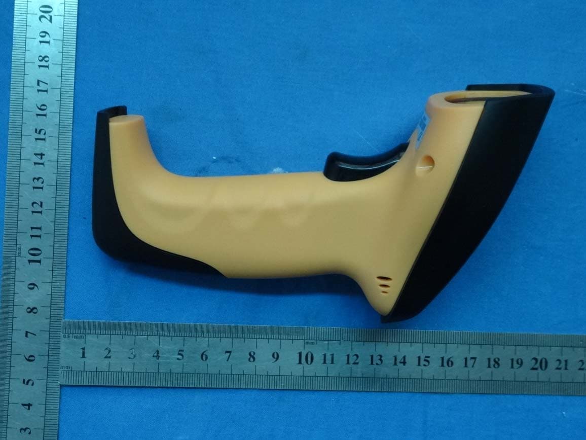
Click to zoom
Application Details
- Equipment Class
- DSR - Part 15 Remote Control/Security Device Transceiver
- Date of Grant
- May 20, 2015
- Application Purpose
- Original Equipment
- Date of Application
- May 20, 2015
- Equipment Note
- Wireless Barcode Scanner
- Frequency Range
- 463.60000000 - 463.60000000
- Country
- China
Documents & Files
Document Text
Text extracted from the exhibit documents filed with the FCC. Open a document above to read the original.
Users Manual
Wireless Barcode Scanner Quick Reference Guide Set Defaults FCC-ID: 2AET8TS4500H VER: TS45_QG_EN_V1.1.0 Scanner & Cradle ① Power Indicator ② Data Indicator ③ Trigger ④ Exit Window ①. Pairing ⑥. Reserve ②. Channel Increase ③. Channel Decrease ④. Power Indicator ⑤. Data Indicator ⑦. Power interface ⑧. Data interface to connect PC ⑨. Adjust button ⑩. Antenna Installation Step 1. Refer to the below pictures, connect the cradle to host (e.g. PC) with different cables firstly, and then connect the adaptor to the power socket. USB : USB cable RJ45 connect cradle ⑧ , the other side connect PC. USB cable P/S 2: P/S2 cable RJ45 connect cradle ⑧ , the other side to connect PC and P/S2 port keyboard P/S2 keyboard cable RS232 : RS232 cable RJ45 side to connect ⑧ ,the other side to connect PC. RS232 cable Typically, cradle is able to identify the data port type automatically. In extreme cases cradle port may need setting manually if the host fails to identify it. Note: Pairing before set interface type. Automatic Identification (Default) USB PS/2 RS232 Step 2. Put the scanner onto the cradle like below picture. Place the Scanner Step3. Press cradle middle button ①( P ) for about 4 seconds, until the Scanner issued a "beep beep" sound. Note: A cradle is able to work with as more as 100 scanners at the same time. After a Scanner pairing with Cradle, the cradle can receive the data from the scanner. Usage of Scanner Power Up/Power Down Scanner will be power up when the trigger is clicked. When the scanner is not operated for 30s, it will enter power down mode automatically Charging Position the scanner onto the cradle. Note : The scanner power indicator becomes green and keeps flashing when the scanner is low power. Built-in Data Memory When the scanner is out of communication area of the cradle, the scanner will save the barcode da ta in built-in data memory. The scanner will send the data to the cradle automatically when the scanner gets back to the communication area. The scanner data indicator will beco me red. After finish sending data, the indicator will to be green. More Than One Cradle Work In The Same Space When there are more than one cradles working in the same space, it is better to set every cradle work in different channel. Channel is set as follows: 1. Open a notepad or other text editor. 2. Press the cradle Channel increase or decrease button. 3. Pairing the scanner and cradle. Note : After changing the channel of a cradle pairing is need. When more than one crad le work in the same channel, it will reduce the bar code data transmission sp eed, but no any other problems. Indicator & Button Scanner Indicator Status Left Light Scan Success Bright Red 1sec Bright Red 1sec Power on Green Low Power Green flashing Charging Red flashing Finish charge Yellow No data stored in Green Scanner Data stored In Scanner Red Data memory full Red Flashing Cradle Indicator Light Meaning Right ( Green ) Flashing: identifying interface On: interface if identified Middle ( Red ) Flashing: Receiving barcode data On: Data is sending to PC Left ( Green) Reserve Cradle Button Button Position( mark ) Function Channel Decrease Right Button (-) Set channel decrease Channel increase Middle (P) Press for 4second to pair a scanner with a cradle. Channel increase Left Button (+) Set channel increase Common Settings Set Defaults Set Defaults Information inquire Fire Ware Version Scanner Serial No Check Cradle Serial No Battery inquire Channel &scanner ID Suffix Quick Setup CR ( default ) LF CR+LF None RF Transfer Mode No-store Mode: The scanner transmits ev ery scanned barcode to cradle. If transmitted unsuccessfully (e.g. beyond communication distance or cradle does not connect PC), the barcod e data will be ignored and the issued a “beep beep beep” sound. Auto-store Mode : The scanner starts storin g barcode data when it loses its connection to a cradle (e.g . a user holding the scanner walks out of range).Data transmission is triggered by reestablishing the connection with cradle.(like when a user holding the scanner walks back into range) Manual Transmission mode: Data transmission is triggered by scanning”Start transfer Bar code data” Auto-Store Mode (Default) NO-Store Mode Manual Transmission Mode Start transfer Bar Code Data (for Manual Transmission Mode) Clear the Barcode Data in Scanner Insert The Scanner ID before Barcode Insert the scanner ID before barcode in order to identify the barcode is scan by which scanner when there are more than one scanner communicate with the same cradle. Insert ID before Barcode Do not insert ID before Barcode ( default ) Code name transmission Transmit Do Not Transmit ( Default ) Volume of beeper High ( Default ) Middle Low Mute Prefix Transmit Prefix Do not Transmit Prefix (Default) Scan Prefix(0~16 Chars, 2Digits/Char; 00~FF; 00* ) Suffix Suffix ( Default ) Do Not Transmit Suffix Scan Suffix (0~22 chars, 2 Digits/Char; 00~FF; 0D*) Parameter bar code 0 1 2 3 4 5 6 7 8 9 A B C D E F Finish Setting FCC Statement Changes or modifications not expressly approved by the party responsible for compliance could void the user's authority to operate the equipment. This equipment has been tested and found to comply with the limits for a Class B digital device, pursuant to Part 15 of the FCC Rules. These limits are designed to provide reasonable protection against harmful interference in a residential installation. This equipment generates uses and can radiate radio frequency energy and, if not installed and used in accordance with the in structions, may cause harmful interference to radio communications. However, there is no guarantee that interference will not occur in a particular installation. If this equipment does cause harmful interference to radio or television reception, which can be determined by turning the equipm ent off and on, the user is encouraged to try to correct the interference by one or more of the following measures: -- Reorient or relocate the receiving antenna. -- Incr…
Text truncated - open the document above for the full version.
Cover Letter(s)
Date:May 05,2015 Title: Manager
Cover Letter(s)
Letter of Authorization Narme: Sammy Zheng Date: May 05, 20'15 Tlirle: Manager
ID Label/Location Info
FCC ID: 2AET8TS4500H FCC ID LABEL: LABEL SIZE: L*W=30mm*8mm FCC ID: 2AET8TS4500H TICODE
Test Report
The results detailed in this test report relate only to the specific sample(s) tested. It is the Application’s responsibility to ensure that all production units are manufactured with equivalent EMC characteristics. This report is not to be reproduced except in full, without written approval from Shenzhen POCE Technology Co., Ltd.. FCC ID TEST REPORT Prepared for...............................: GUANGZHOU TAIMA(TICODE) ELECTRONICS TECHNOLOGY LTD. Address.....................................: NO.768, Shenzhou Road, Science City, Luogang, Guangzhou, China Equipment Under Test(E.U.T.): Wireless Barcode Scanner Model...............................................: TS4500H FCC ID.............................................: 2AET8TS4500H Applicable Standards.......................: FCC Part 15:2013 Subpart C, Paragraph 15.231 Test Date...................................: 05 May2015 to 18 May 2015 Issued Date...............................: 18 May 2015 Report Number.........................: POCE15042932SRF Test Engineer............................: Reviewed By.............................: Prepared By...............................: Shenzhen POCE Technology Co., Ltd. H Building, Hongfa Science and Technology Park, Tangtou, Shiyan, Bao’an District, Shenzhen, China Tel: 86-755-2911 3252 Fax: 86-755-2911 3135 Shenzhen POCE Technology Co., Ltd. Report No.: POCE15042932SRF FCC ID: 2AET8TS4500H H Building, Hongfa science and Technology Park, Tangtou, Shiyan, Bao’an District, Shenzhen, China Tel: +86-755-2911 3252 Fax: +86-755-2911 3135 http://www. poce-cert.com Page 2 of 17 Table of Contents 1.0 General Information.............................................................................................................................................. 3 1.1 Client details .................................................................................................................................................... 3 1.2 Test lab details ................................................................................................................................................. 3 1.3 Description of E.U.T. ....................................................................................................................................... 4 1.4 AE used during the test .................................................................................................................................... 4 2.0 Test summary......................................................................................................................................................... 5 3.0 E.U.T. modification................................................................................................................................................ 5 4.0 Measurement Uncertainty.................................................................................................................................... 5 5.0 Power Line Conducted Emission Test.................................................................................................................. 6 5.1 Test equipment ................................................................................................................................................. 6 5.2 Test method and test procedure........................................................................................................................ 6 5.3 Block diagram of test setup ............................................................................................................................. 6 5.4 E.U.T. operating condition............................................................................................................................... 6 5.5 Power line conducted emission limit according to paragraph 15.207 ............................................................. 6 5.6 Test specification ............................................................................................................................................. 6 5.7 Test result......................................................................................................................................................... 6 6.0 Radiated Spurious Emission Test......................................................................................................................... 9 6.1 Test equipment ................................................................................................................................................. 9 6.2 Limit ................................................................................................................................................................ 9 6.3 E.U.T. operating condition............................................................................................................................. 10 6.4 Test specification ........................................................................................................................................... 10 6.5 Block diagram of test setup ........................................................................................................................... 11 6.6 Test procedure................................................................................................................................................ 12 6.7 Test result....................................................................................................................................................... 12 7.0 20dB Bandwidth Measurement.......................................................................................................................... 16 7.1 Test equipment ............................................................................................................................................... 16 7.2 Test specification ........................................................................................................................…
Text truncated - open the document above for the full version.
Contact Information
Applicant
Sammy Zheng(Manager)
Technical Contact
Shenzhen POCE Technology Co., Ltd.Jack Kang
[email protected](86)75529113252
Room 502, Bldg. 1, Xinghua Garden · Shenzhen · China
Test Firm
Shenzhen POCE Technology Co.,Ltd.Bill Yuan
Technical Specifications
| # | Rule Parts | Frequency Range | Power Output |
|---|---|---|---|
| 1 | 15.231(e) | 463.6 MHz - 463.6 MHz | - |