2AEX2GT9000GT-9000
Globaltronics gmbH & Co KG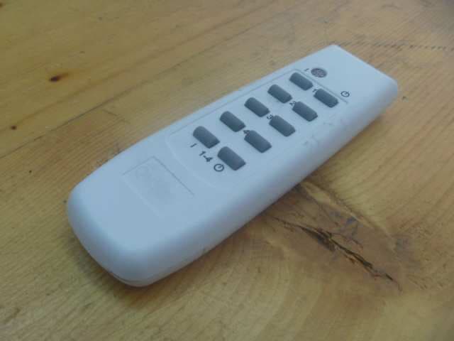
Click to zoom
Application Details
- Equipment Class
- DSC - Part 15 Security/Remote Control Transmitter
- Date of Grant
- Jun 09, 2015
- Application Purpose
- Original Equipment
- Date of Application
- Jun 08, 2015
- Equipment Note
- GT-9000
- Frequency Range
- 433.92000000 - 433.92000000
- Company
- Globaltronics gmbH & Co KG
- Country
- Germany
Documents & Files
Document Text
Text extracted from the exhibit documents filed with the FCC. Open a document above to read the original.
Users Manual
Remote Control Socket Model: GT-FSI-07-US + GT-9000 Please read the entire instruction manual before using the product and then save it for future reference. We reserve the right for any errors in text or images and any necessary changes made to technical data. If you have any questions concerning technical problems please contact our Customer Services. Safety •This set of switches is suitable for controlling devices such as lights. • Make sure that the load device is turned off before connecting it to the receiver. • Never connect a load device with a higher power rating than 180 0 W. •These switches are intended for indoor use; do not expose them to rain or moisture. 3. Each receiver has an indicator in the socket showing which of the buttons (1, 2, 3,or 4) it is programmed for. The indicator should be removed the first time the receiver is used. If the programming does not work for some reason, the programming must be re-done. Refer to the New programming section. Operating instructions Note: Do not touch any of the buttons on the transmitter before the LED indicator has stopped flashing, otherwise the programming will change. 1.Plug receiver A into an electrical socket. 2. The LED indicator on the receiver will begin to flash slowly for 30 seconds and then go out. 3.The on/off switching of the socket built into receiver A will now be controlled by button [ 1–ON ] and [ 1–OFF ]. The LED indicator on the receiver will come on when the receiver is switched on and go out when the receiver is switched off. 4. The other three receivers will be controlled in the same way but with buttons [ 2–ON ], [ 2–OFF ] [ 3–ON ], [ 3–OFF ], and [ 4–ON ], [ 4–OFF ] respectively. 5. Buttons [ 1-4–ON ] and [ 1-4–OFF ] are from the outset pre-programmed to control all four receivers simultaneously. Note: Each time a receiver is unplugged from an electrical socket and plugged in again, it goes into learning mode (the LED indicator flashes slowly) for 30 seconds. In learning mode, a channel can be added or several channels can be removed. All the channels, (1, 2, 3, 4 and 1-4) can be a put on one receiver if desired. Refer to the Deleting the programming and New programming sections. Deleting the programming 1.Unplug the receiver from the electrical socket. 2. Plug the receiver into an electrical socket after about 10 seconds. 3.The LED indicator on the receiver will flash slowly for 30 seconds while it is in learning mode. 4. Press the desired [ OFF ] button while the LED indicator is flashing to delete the programming. The LED indicator will flash quickly whilst the programming is being deleted. 5. Once programming has been deleted, the receiver is no longer programmed to any of the buttons on the transmitter. New programming The receiver needs to be programmed to one of the buttons 1, 2, 3, 4 or 1-4 as follows: 1.Unplug the receiver from the electrical socket. 2.Plug the receiver into an electrical socket after about 10 seconds. 3. The LED indicator on the receiver will flash slowly for 30 seconds while it is in learning mode. 4. Press [ 1–ON ], [ 2–ON ], [ 3–ON ] , [ 4–ON ] or [ 1-4–ON ] whilst the LED indicator is flashing to programme the receiver to the transmitter. 5. The LED indicator comes on when the programming is completed. 6. Follow the same procedure with the other receivers. The LED indicator on the receiver shows the status of the receiver in 4 different ways: • The receiver socket is switched off when the LED indicator is not on. • The receiver socket is switched on when the LED indicator is on. • The LED indicator flashes slowly for 30 seconds when the receiver is in learning mode. • The LED indicator flashes quickly whilst the programming is being deleted. Care and maintenance •Unplug the mains lead before cleaning the product. •Clean the product using a soft, moist cloth. Only use mild detergents; never use solvents or strong, abrasive cleaning agents for cleaning as these can damage the product. Disposal This product should be disposed of in accordance with local regulations. If you are unsure how to proceed, contact your local council. Specifications GT-FSI-07-US (receiver) Rated voltage 120 V AC, 60 Hz Max load 1 800 W ( 15 A) GT-9000 (transmitter) Battery 12VDC,Type A 23 Frequency 433.92 MHz Range up to 25 metres (line-of-sight) TransmitterReceiver Before use Inserting the transmitter battery 1.Press the catch on the battery cover in the direction of the arrow and remove it. Insert the included battery into the transmitter in accordance with the markings in the battery compartment. Refit the battery cover. 2. The receivers are already preprogrammed for buttons 1, 2,3 and 4 on the transmitter. Button E controls all three receivers simultaneously. Caution This device complies with Part 15 of the FCC. Operation is subject to the following two conditions: (1) this device may not cause harmful interference, and (2) this device must accept any interference received, including interference that may cause undesired operation. Changes or modifications not expressly approved by the party responsible for compliance could void the user's authority to operate the equipment. This equipment has been tested and found to comply with the limits for a Class B digital device, pursuant to part 15 of the FCC Rules. These limits are designed to provide reasonable protection against harmful interference in a residential installation. This equipment generates uses and can radiate radio frequency energy and, if not installed and used in accordance with the instructions, may cause harmful interference to radio communications. However, there is no guarantee that interference will not occur in a particular installation. If this equipment does cause harmful interference to radio or television reception, which can be determined by turning the equipment off and on, the user is encouraged to try to correct the interference by one or more of the following measures: —Reorient or relocate the receiving antenna. —Increas…
Text truncated - open the document above for the full version.
External Photos
FCC ID: 2AEX2GT9000 Page 1 of 1 External Picture
ID Label/Location Info
Label position
Internal Photos
FCC ID: 2AEX2GT9000 Page 1 of 1 Internal Picture
Test Report
FCC ID: 2AEX2GT9000 Page 1 of 13 Test Data FCC ID: 2AEX2GT9000 Page 2 of 13 1. Fundamental & Spurious Emission & Restrict band radiated emission Horizontal 30-1000MHz 0 20 40 60 80 100 Level [dBμV/m] 30M50M70M100M 200M300M500M 700M 1G Frequency [Hz] x x x x x x x MES NE0603_LV1_red MES NE0603_LV1_pre LIM FCC 15 F 3 QP Field Strength QP FCC ID: 2AEX2GT9000 Page 3 of 13 Restrict band 0 10 20 30 40 50 60 70 80 Level [dBμV/m] 399.9M402M 404M 406M 408M410M Frequency [Hz] MES ak0529_lH_pre LIM FCC 15 F 3 QP Field Strength QP FCC ID: 2AEX2GT9000 Page 4 of 13 Horizontal 1000-6000 MHz 0 10 20 30 40 50 60 70 80 Level [dBμV/m] 1G2G3G4G5G Frequency [Hz] x x MES NE0603_HH1_red MES NE0603_HH1_pre LIM FCC 15 F 3 PK Field Strength QP LIM FCC 15 F 3 AV Field Strength QP FCC ID: 2AEX2GT9000 Page 5 of 13 Vertical 30-1000MHz 0 10 20 30 40 50 60 70 80 Level [dBμV/m] 30M50M70M100M 200M300M500M 700M 1G Frequency [Hz] x x x x x x MES 0603JXV1_red MES 0603JXV1_pre LIM FCC 15 F 3 QP Field Strength QP FCC ID: 2AEX2GT9000 Page 6 of 13 Restrict band 0 10 20 30 40 50 60 70 80 Level [dBμV/m] 399.9M402M 404M406M 408M 410M Frequency [Hz] LIM FCC 15 F 3 QP Field Strength QP MES ak0529_VL_pre FCC ID: 2AEX2GT9000 Page 7 of 13 Vertical 1000-6000MHz 0 10 20 30 40 50 60 70 80 Level [dBμV/m] 30M50M70M100M 200M300M500M 700M 1G Frequency [Hz] x x x x x x MES 0603JXV1_red MES 0603JXV1_pre LIM FCC 15 F 3 QP Field Strength QP FCC ID: 2AEX2GT9000 Page 8 of 13 2. Deactivating time FCC ID: 2AEX2GT9000 Page 9 of 13 3. Emission bandwidth FCC ID: 2AEX2GT9000 Page 10 of 13 4. Duty Cycle FCC ID: 2AEX2GT9000 Page 11 of 13 FCC ID: 2AEX2GT9000 Page 12 of 13 FCC ID: 2AEX2GT9000 Page 13 of 13 All the keys were assessed and the test data with maximum duty cycle was listed above. The worst Duty cycle= (11*1.156+ 0.956*13+3.156) / 47.702 = 0.59
Test Report
FCC ID: 2AEX2GT9000 Page 1 of 19 EMC TEST REPORT No. 150500821SHA-001 Applicant : Globaltronics GmbH & Co.KG Domstrasse 19, 20095 Hamburg,Germany Manufacturer : Kangtai Electric Co., Ltd. No.5, Kangtai Rd., Huanghua Industrial District, Yueqing, Zhejiang, P.R.China Equipment : Remote control transmitter Type/Model : GT-9000 SUMMARY The equipment complies with the requirements according to the following standard(s): 47CFR Part 15 (2014): Radio Frequency Devices ANSI C63.10 (2009): American National Standard for Testing Unlicensed Wireless Devices Date of issue: June 03, 2015 Prepared by: Reviewed by: Jesse Xu (Project Engineer) Daniel Zhao (Reviewer) FCC ID: 2AEX2GT9000 Page 2 of 19 Description of Test Facility Name: Intertek Testing Services Limited Shanghai Address: Building No.86, 1198 Qinzhou Road(North), Shanghai 200233, P.R. China FCC Registration Number: 236597 IC Assigned Code: 2042B-1 Name of contact: Steve Li Tel: +86 21 64956565 ext. 214 Fax: +86 21 54262335 ext. 214 FCC ID: 2AEX2GT9000 Page 3 of 19 Content SUMMARY .......................................................................................................................................................... 1 DESCRIPTION OF TEST FACILITY ......................................................................................................................... 2 1. GENERAL INFORMATION ............................................................................................................................ 4 1.1 Applicant Information ..................................................................................................... 4 1.2 Identification of the EUT ................................................................................................ 4 1.3 Technical specification ................................................................................................... 5 1.4 Mode of operation during the test / Test peripherals used .............................................. 5 2. TEST SPECIFICATION .................................................................................................................................. 6 2.1 Instrument list ................................................................................................................. 6 2.2 Test Standard .................................................................................................................. 6 3. FUNDAMENTAL & SPURIOUS EMISSION & RESTRICT BAND RADIATED EMISSION ................................... 7 3.1 Test limit ......................................................................................................................... 7 3.2 Test Configuration .......................................................................................................... 8 3.3 Test procedure and test setup .......................................................................................... 8 3.4 Test protocol ................................................................................................................... 9 4. DEACTIVATING TIME ................................................................................................................................ 11 4.1 Test limit ....................................................................................................................... 11 4.2 Test Configuration ........................................................................................................ 12 4.3 Test procedure and test setup ........................................................................................ 12 4.4 Test protocol ................................................................................................................. 12 5. POWER LINE CONDUCTED EMISSION ........................................................................................................ 13 5.1 Limit .............................................................................................................................. 13 5.2 Test configuration ......................................................................................................... 13 5.3 Test procedure and test set up ....................................................................................... 14 5.4 Test protocol ................................................................................................................. 15 6. EMISSION BANDWIDTH ............................................................................................................................. 16 6.1 Test limit ....................................................................................................................... 16 6.2 Test Configuration ........................................................................................................ 16 6.3 Test procedure and test setup ........................................................................................ 16 6.4 Test protocol ................................................................................................................. 17 7. OCCUPIED BANDWIDTH ............................................................................................................................ 18 7.1 Test limit ....................................................................................................................... 18 7.2 Test Configuration ........................................................................................................ 18 7.3 Test procedure and test setup ........................................................................................ 18 7.4 Test protocol ................................................................................................................. 19 FCC ID: 2AEX2GT9000 Page 4 of 19 1. General Information 1.1 Applicant Information Applicant: Globaltronics GmbH & Co.KG Domstrasse 19, 20095 Hamburg,Germany Name of contact: Plesinger, Frank Tel: 49 40 333 12 279 F…
Text truncated - open the document above for the full version.
Test Setup Photos
FCC ID: 2AEX2GT9000 Page 1 of 2 Test Setup FCC ID: 2AEX2GT9000 Page 2 of 2 1. Radiated Emission Above 1GHz Below 1GHz
Contact Information
Applicant
Frank Plesinger
Technical Contact
Intertek Testing Services Limited ShanghaiJesse Xu
[email protected]86-21-61215147
Building No.86, 1198 Qinzhou Road(North) · Shanghai · China
Test Firm
Intertek Testing Services Limited ShanghaiJonny Jing
Technical Specifications
| # | Rule Parts | Frequency Range | Power Output |
|---|---|---|---|
| 1 | 15.231 | 433.92 MHz - 433.92 MHz | - |