2AEXEIPPROWLT10Wireless Network Camera
Plustek Inc.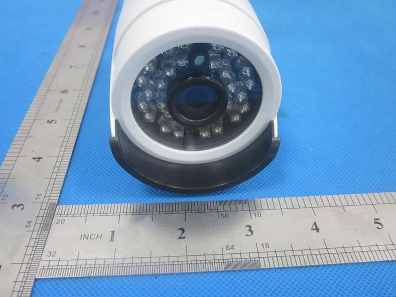
Click to zoom
Application Details
- Equipment Class
- NII - Unlicensed National Information Infrastructure TX
- Date of Grant
- Jul 15, 2015
- Application Purpose
- Original Equipment
- Date of Application
- Jul 15, 2015
- Equipment Note
- Wireless Network Camera
- Frequency Range
- 5745.00000000 - 5825.00000000
- Company
- Plustek Inc.
- Country
- Taiwan
Documents & Files
Document Text
Text extracted from the exhibit documents filed with the FCC. Open a document above to read the original.
Users Manual
NVR&HVR Easy guide v1.0 1 W W i i r r e e l l e e s s s s N N e e t t w w o o r r k k C C a a m m e e r r a a N N V V R R & & H H V V R R Easy guide Thanks for choosing our products, please read this manual carefully before use! NVR&HVR Easy guide v1.0 2 1. NVR connect to IPCAM 1)Search IPCAM Click CAMERA icon, popup CHANNEL CONFIG sub menu. FAB IDCAM Onvif IPCAM FAB IPCAM Analog cam NVR&HVR Easy guide v1.0 3 Click SEARCH button, after 20 seconds,all IPCAM ID number or IP address in local network will be displayed in menu, and auto assign to deferent channel,click SAVE, exit menu, All IPCAM image will display. 2)Manual add in IPCAM Click MENU button. Select deferent channel, use mouse wheel to change CAM IP/ID, you can input IP address or ID number. V0000110—Onvif IPCAM, IP address is 110 NVR&HVR Easy guide v1.0 4 00000111---FAB IPCAM, IP address is 111 001CD23A--- FAB IDCAM, ID number is 001CD23A 00000BNC---Analog camera input Please note the following instructions BACKLIGHT---If set ON, camera shine on outdoor, it will be overexposure; camera shine on indoor, it can enhance the brightness of the backlight; DAY CDS---More low more easy to start day mode, on day mode, image is color and ir turn off; Note---For analog video input, DAY CDS need set to 230-255, then image can be move to the middle. NIGHT CDS—More high more easy to start night mode, on night mode, image is black white and ir turn on; SUB STREAM---This function only for FAB protocol IPCAM, if set CIF, split image resolution only 320*240, but image very fluid. Internet also become fluid。 2. NVR connect to cloud Nvr connect to cloud, then mobile APP and client software can connect to NVR over internet. Click NETWORK icon. NVR&HVR Easy guide v1.0 5 Enable DDNS and CLOUD, Click DHCP button, NVR will get IP address from router, click SAVE. Click INFO icon, popup INFORMATION submenu. NVR&HVR Easy guide v1.0 6 In DDNS line, domain name and machine number display, if you see @ symbol, mean NVR already connect to cloud server。 3. Mobile APP connect to NVR If you are using this software for the first time, please download the software of “HVR cloud”, setup the software, then open. Click Device manage button in login interface, NVR&HVR Easy guide v1.0 7 Click SEARCH button, search all NVR in local network. NVR&HVR Easy guide v1.0 8 Select NVR number what you want to view, return login interface, select CLOUD, click LOGIN, APP will connect NVR. 4. CMS connect to NVR Copy CMS software to PC from disk, this CMS software is green software, no need setup, double click start.exe in folder to run the software. Note: windows firewall may be popup tips, ask whether to allow network access, you must select “allow”, if you're not careful to select “forbid”, please copy the folder to other disk, run software again. 1) Auto search NVR&HVR Easy guide v1.0 9 After run the software, device list window will display all NVR in local network, right click NVR/CMS, click “turn off NVR auto search”, will stop auto search NVR function; Select NVR device, right click, click “Connect”, if NVR and PC is same network segment, CMS will display NVR image. NVR&HVR Easy guide v1.0 10 Select NVR, right click, click “property”, enable “cloud mode”, show name can be modified into easy remember name. 2) Manual add in Right click NVR/CMS,select“new IP”,input login machine information,enable cloud mode,click OK to exit menu,right click new device, select “connect” 3) After input machine information in CMS,you can zip the folder,send email to yourself or your customer. Then download to use on other place。 NVR&HVR Easy guide v1.0 11 3. FCC Statement This equipment has been tested and found to comply with the limits for a Class B digital device, pursuant to Part 15 of the FCC Rules. These limits are designed to provide reasonable protection against harmful interference in a residential installation. This equipment generates uses and can radiate radio frequency energy and, if not installed and used in accordance with the instructions, may cause harmful interference to radio communications. However, there is no guarantee that interference will not occur in a particular installation. If this equipment does cause harmful interference to radio or television reception, which can be determined by turning the equipment off and on, the user is encouraged to try to correct the interference by one or more of the following measures: -- Reorient or relocate the receiving antenna. -- Increase the separation between the equipment and receiver. -- Connect the equipment into an outlet on a circuit different from that to which the receiver is connected. -- Consult the dealer or an experienced radio/TV technician for help. This device complies with part 15 of the FCC Rules. Operation is subject to the following two conditions:(1) This device may not cause harmful interference, and (2) this device must accept any interference received, including interference that may cause undesired operation. Changes or modifications not expressly approved by the party responsible for compliance could void the user's authority to operate the equipment. This equipment complies with FCC radiation exposure limits set forth for an uncontrolled environment. This equipment should be installed and operated with minimum distance 20cm between the radiator & your body.
Cover Letter(s)
SCS-F19: Confidentiality Request Letter Page 1 of 3 Rev 4.0 775 Montague Expressway Milpitas, CA 95035 Tel: 408-526-1188 Fax: 408-526-1088 Email: [email protected] Confidentiality Request Letter Reason for Amendment (current / obsolete) Revision History Approved Date From To Initial Release (obsolete) 1.0 1.0 Nov-14-2006 Adding CFR 2.459 (obsolete) 1.0 2.0 August – 11 - 2008 Updated company template & Added text box (obsolete) 2.0 3.0 Jan-31-2012 Added IC confidentiality letter form (current) 3.0 4.0 March-26-2015 SCS-F19: Confidentiality Request Letter Page 2 of 3 Rev 4.0 Plustek Inc. 2015/06/18 To: Federal Communications Commission Authorization and Evaluation Division 7435 Oakland Mills Road Columbia, MD Subject: Permanent Confidentiality Request for FCC ID: 2AEXEIPPROWLT10 We hereby request confidential treatment of information accompanying this application as outlined below: - Block Diagram - Schematics - Operational Description - FCC SW SECURITY DESCRIPTION The above materials contain trade secrets and proprietary information not customarily released to the public. The public disclosure of these materials may be harmful to the applicant and provide unjustified benefits to its competitors. The applicant understands that pursuant to Section 0.457 & 0.459 of the Rules, disclosure of this application and all accompanying documentation will not be made before the date of the Grant for this application. Sincerely, Client’s signature Client’s name / title : Tony Chien / Safety Engineer Contact informations: 13F-1, No. 3, Yuan Qu St., 115 Nankang, Taipei, Taiwan
Cover Letter(s)
SCS-F18: Project and Product Certification Representative Authorization Letter Page 1 of 2 Rev 5.0 775 Montague Expressway Milpitas, CA 95035 Tel: 408-526-1188 Fax: 408-526-1088 Email: [email protected] Project and Product Certification Representative Authorization Letter Reason for Amendment (current / obsolete) Revision History Approved Date From To Initial Release (obsolete) 1.0 1.0 Nov-14-2006 Revised wording (obsolete) 1.0 2.0 Sept–25-2007 Updated company template (obsolete) 2.0 3.0 Jan-31-2012 Updated letter information (obsolete) 3.0 4.0 May-23-2014 Added FCC ID field (current) 4.0 5.0 Sept 16 2014 SCS-F18: Project and Product Certification Representative Authorization Letter Page 2 of 2 Rev 5.0 Plustek Inc. 2015/06/18 To: SIEMIC, INC. 775 Montague Expressway, Milpitas, CA 95035 USA Dear Sir/Madam, Re: Product Certification Representative Authorization Letter We, Plustek Inc. hereby authorize SIEMIC, Inc. to act as a Certification Body for certifying for the following project(s): Product description: Wireless Network Camera model name: IP PRO WLT10, IP PRO W****** Trademark: Plustek FCC ID: 2AEXEIPPROWLT10 Sincerely, Client’s signature Client’s name / title : Tony Chien / Safety Engineer Contact informations: 13F-1, No. 3, Yuan Qu St., 115 Nankang, Taipei, Taiwan
Cover Letter(s)
Plustek Inc. Federal Communications Commission Authorization and Evaluation Division 1435 Oakland Mills Road Columbia, MD 21046 Date: SUBJECT: FCC Application for (FCC ID: 2AEXEIPPROWLT10) To Whom It May Concern: We, the undersigned, hereby attest to the fact that we will apply the Declaration of Conformity procedure to the class B computer peripheral portion of this composite device. We understand that devices subject to the DoC procedure are required to be tested to show compliance with the FCC technical regulations by a recognized accredited testing laboratory. The testing laboratory must be accredited by a Commission approved accreditation body or designated under the terms of a government-to-government Mutual Recognition Agreement (MRA). A listing of those accredited testing laboratories that have been recognized by the Commission is published on the FCC Webpage: https://apps.fcc.gov/oetcf/eas/reports/TestFirmSearch.cfm Select the "accredited" option to search for FCC recognized accredited test firms. Test facilities located in countries, where the U.S. does not have an operational Telcom MRA are not recognized by the FCC to test for the DoC procedure. Regards, Signatory Client’s name / title : Tony Chien / Safety Engineer Contact informations: 13F-1, No. 3, Yuan Qu St., 115 Nankang, Taipei, Taiwan
Cover Letter(s)
Plustek Inc. Family letter Product Name: Wireless Network Camera Brand Name: Plustek The main test model : IP PRO WLT10 Additional models for: IP PRO W****** Primary check model and additional model at the same electrical principle, PCB shape and structure, is different for appearance color. Client’s name / title : Tony Chien / Safety Engineer Contact informations: 13F-1, No. 3, Yuan Qu St., 115 Nankang, Taipei, Taiwan
ID Label/Location Info
Label location
Internal Photos
Antenna Location A Antenna Location B
RF Exposure Info
FCC ID: 2AEXEIPPROWLT10 1. RF EXPOSURE EVALUATION 1.1. Limits The criteria listed in the following table shall be used to evaluate the environment impact of human exposure to radio frequency (RF) radiation as specified in 1.1307(b) Limits for Maximum Permissible Exposure (MPE) f = frequency in MHz Friis transmission formula: Pd = (Pout*G)/(4*pi*r 2 ) Where Pd = power density in mW/cm 2 , Pout = output power to antenna in mW; G = gain of antenna in linear scale, Pi = 3.1416; R = distance between observation point and center of the radiator in cm Pd id the limit of MPE, 1 mW/cm 2 . If we know the maximum gain of the antenna and the total power input to the antenna, through the calculation, we will know the distance r where the MPE limit is reached. 1.2. Test Procedure Software provided by client enabled the EUT to transmit and receive data at lowest, middle and highest channel individually. FCC ID: 2AEXEIPPROWLT10 1.3. Test Result of RF Exposure Evaluation Target power W/ tolerance (dBm) Max tune up power tolerance (dBm) Total Output power to antenna (mW) Antenna Gain(dBi) Total Power Density at R=20cm (mW/cm 2 ) Limit (mW/cm 2 ) Result Ant. AAnt. B 15±1.0 16.0 16.0 79.62 3.0 0.0316 1.0 Pass
Test Report
Shenzhen BCTC Technology Co., Ltd. Report No.: BCTC-15060079 FCC Report Tel: 400-788-9558 0755-33019988 Web:Http//www.bctc-lab.com Page 1 of 37 FCC Part 15C Test Report FCC ID: 2AEXEIPPROWLT10 Product Name: Wireless Network Camera Trademark: Plustek Model Name : IP PRO WLT10, IP PRO W****** (The " * " can be 0-9 , a-z, A-Z or blank , for marketing purpose ) Prepared For : Plustek Inc. Address : 13F-1, No. 3, Yuan Qu St., 115 Nankang, Taipei, Taiwan Prepared By : Shenzhen BCTC Technology Co., Ltd. Address : No.101,Yousong Road,Longhua New District, Shenzhen,China Test Date: Jun. 8– Jun. 15, 2015 Date of Report : Jun. 16, 2015 Report No.: BCTC-15060079 Shenzhen BCTC Technology Co., Ltd. Report No.: BCTC-15060079 FCC Report Tel: 400-788-9558 0755-33019988 Web:Http//www.bctc-lab.com Page 2 of 37 VERIFICATION OF COMPLIANCE Applicant’s name ............. : Plustek Inc. Address .............................. : 13F-1, No. 3, Yuan Qu St., 115 Nankang, Taipei, Taiwan Manufacture's Name ........ : Plustek Inc. Address .............................. : 13F-1, No. 3, Yuan Qu St., 115 Nankang, Taipei, Taiwan Product description Product name ......................... : Wireless Network Camera Trademark: Plustek Model Name: IP PRO WLT10, IP PRO W****** (The " * " can be 0-9 , a-z, A-Z or blank , for marketing purpose ) Test procedure FCC Part15.407 Standards ANSI C63.10-2013 This device described above has been tested by BCTC, and the test results show that the equipment under test (EUT) is in compliance with the FCC requirements. And it is applicable only to the tested sample identified in the report. This report shall not be reproduced except in full, without the written approval of BCTC, this document may be altered or revised by BCTC, personal only, and shall be noted in the revision of the document. Test Result : Pass Testing Engineer : (Eric Yang) Technical Manager : (Sophia Lee) Authorized Signatory : (Carson. Zhang) Shenzhen BCTC Technology Co., Ltd. Report No.: BCTC-15060079 FCC Report Tel: 400-788-9558 0755-33019988 Web:Http//www.bctc-lab.com Page 3 of 37 TABLE OF CONTENTS Test Report Declaration Page 1. TEST SUMMARY ............................................................................................................. 4 2. GENERAL PRODUCT INFORMATION ............................................................................ 5 2.1. Product Function .................................................................................................................... 5 2.2. Description of Device (EUT) .................................................................................................. 5 2.3. Test Supporting System ......................................................................................................... 6 2.4. Independent Operation Modes .............................................................................................. 6 2.5. Test Sites ............................................................................................................................... 6 2.6. List of Test and Measurement Instruments ............................................................................ 7 3. TEST SET-UP AND OPERATION MODES ...................................................................... 8 3.1. Principle of Configuration Selection ....................................................................................... 8 3.2. Block Diagram of Test Set-up ................................................................................................ 8 3.3. Test Operation Mode and Test Software ............................................................................... 8 3.4. Special Accessories and Auxiliary Equipment ....................................................................... 8 3.5. Countermeasures to Achieve EMC Compliance .................................................................... 8 4. EMISSION TEST RESULTS ............................................................................................. 9 4.1. Conducted Emission Measurement ....................................................................................... 9 4.2. Radiated Emission Measurement ........................................................................................ 13 5. BAND EDGE COMPLIANCE TEST ................................................................................ 23 5.1. Limits .................................................................................................................................... 23 5.2. Test setup ............................................................................................................................ 23 5.3. Test Data ............................................................................................................................. 23 6. 6DB AND 99% BANDWIDTH TEST ............................................................................... 24 6.1. Measurement Procedure ..................................................................................................... 24 7. OUTPUT POWER TEST ................................................................................................ 29 7.1. Limits .................................................................................................................................... 29 7.2. Test setup ............................................................................................................................ 29 7.3. Test result ............................................................................................................................ 29 8. PEAK POWER SPECTRAL DENSITY TEST ................................................................. 30 8.1. Limits .................................................................................................................................... 30 8.2. Test setup ....................................................................................…
Text truncated - open the document above for the full version.
Test Setup Photos
Radiated Emission conducted Emission
Contact Information
Applicant
Rick Chu
Test Firm
Shenzhen BCTC Technology Co., Ltd.James Zhang
Technical Specifications
| # | Rule Parts | Frequency Range | Power Output |
|---|---|---|---|
| 1 | 15E | 5.75 GHz - 5.83 GHz | 67.90 mW |
Other Applications from Plustek Inc.
2AEXE-A355-22156759
Jul 09, 2026Scanner, Plustek eScan
Equipment Class
NII - Unlicensed National Information Infrastructure TX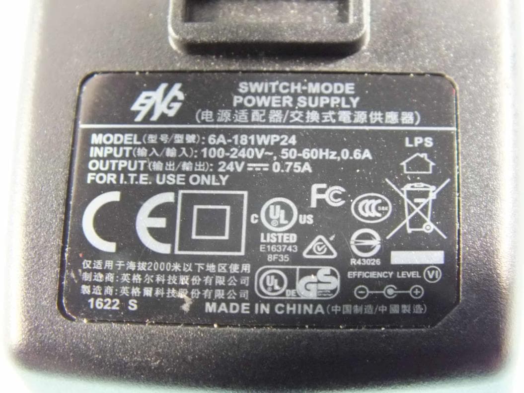
2AEXESECURESCANX200
Aug 11, 2020SecureScan ID Scanner
Equipment Class
DXX - Part 15 Low Power Communication Device Transmitter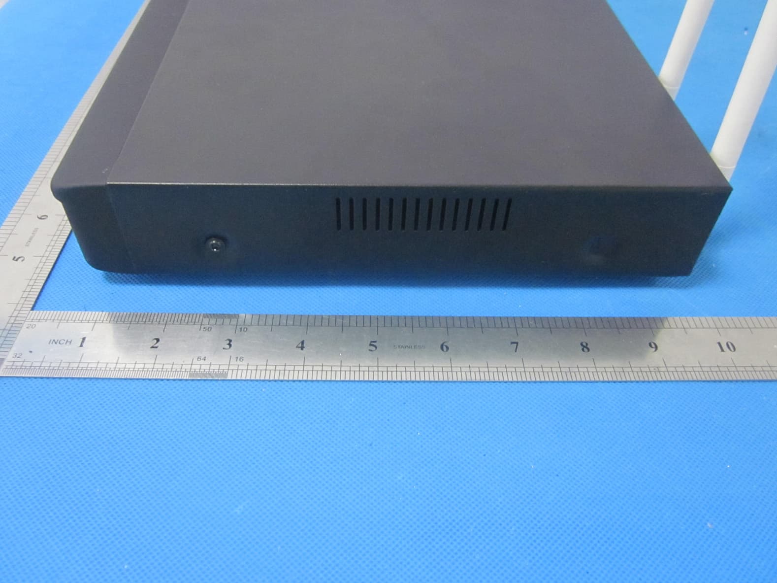
2AEXENVR4W14A
Jul 19, 2015Wireless Network Video Recorder
Equipment Class
NII - Unlicensed National Information Infrastructure TX