2AEY9VLXWireless Microphone (DECT6.0)
PG Electronics.co.,Ltd.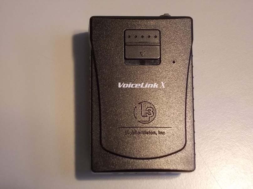
Click to zoom
Application Details
- Equipment Class
- PUT - Part 15 Unlicensed PCS portable Tx worn on body
- Date of Grant
- Aug 23, 2015
- Application Purpose
- Original Equipment
- Date of Application
- Aug 23, 2015
- Equipment Note
- Wireless Microphone (DECT6.0)
- Frequency Range
- 1921.53600000 - 1928.44800000
- Company
- PG Electronics.co.,Ltd.
- Country
- South Korea
Documents & Files
Document Text
Text extracted from the exhibit documents filed with the FCC. Open a document above to read the original.
Users Manual
Page 1 READ ME FIRST! Using Your VLX Wireless Microphone The VoiceLinkX wireless microphone or “VLX” is used to initiate a recording while you are outside your vehicle. If there are two officers sharing one vehicle, you may wish to purchase a second VLX. The DVR supports up to two units. The VLX comes with a docking station that has an antenna attached to it. The antenna is used to communicate with the DVR. In order for the device to operate, the VLX must be synchronized with the docking station. To remove the wireless mic from the docking station, simply tilt it forward, then lift up. Requirements for Successful Recording Using the VLX When using your VLX, please keep the following requirements in mind: Remain within transmission range of the docking station.If your VLX battery is fully charged, the transmission range is a maximum 1,200 feet. If your VLX battery is notfully charged (common scenario), the range may be reduced. Whenever you move outside of range, the unit will vibrate once every five seconds for six consecutive times. In addition, the Signal LED will flash red until the VLX is back in range. Keep the Power switch in the ‘On’ position when using. It’s recommended that you leave the VLX power switch on for the duration of your shift, as pictured right. This switch is located at the base of the mic. Avoid metal barriers between the wireless mic and the docking station. The wireless mic uses a “line of sight” signal. Physical barriers, particularly metalbarriers, can interrupt this signal. Since your vehicle is made of metal, it’s important to mount the VLX above the dashboard line so that the signal does not have to pass through metal. Also, do not try to record while your vehicle is above or below you, as this forces the signal to pass through the vehicle’s undercarriage or roof, respectively. For example, if you are standing on an overpass and your vehicle is parked under the overpass, this creates a metal barrier, as the signal has to pass through the roof of your vehicle. VoiceLinkX wireless microphone with docking station PP_Model: MV-VLX-TR-1.9 FCC: 2AEY9VLX IC: 20293-VLX FP_Model: MV-VLX-DS-1.9 FCC: 2AEY9VL-DS IC: 20293-VLX-DS FP_Model: MV-VLX-DS-1.9 FCC: 2AEY9VLX-DS IC: 20293-VLX-DS VLX Wireless Microphone Rev. 7.13.2015 Page 2 Avoid multiple non-metal barriers between the wireless mic and the docking station. If you walk indoors while a recording is in progress, multiple walls can interrupt the signal between the wireless mic and the docking station. Configure your VLX as a record trigger on the Flashback. If you are using the Fleet Management feature, see “Changing the Triggers for a Flashback DVR that is Not Assigned to a DVR Group” or “Changing the Triggers for a Flashback DVR Group” in the DVRs chapter of your DES Administrator’s Guide. If you arenotusing the Fleet Management feature, see “Selecting & Configuring Record Triggers” in your Flashback User’s Guide. Always maintain a strong battery charge.For more information, see “VLX Battery Considerations” on the next page. Use the VLX with the lapel mic. Although the VLX comes with an internal mic, it is designed only as a backup mic in the event that the lapel mic fails. Whenever possi- ble, use the lapel mic as your primary microphone. If you use the internalmic as your primary microphone, you may encounter audio interference due to wind and road noises that are more easily picked up when a mic is connect- Starting a Recording From the VLX To start a recording, slide the VLX switch down. The unit will vibrate once, indicat- ing that you have successfully initiated a recording. To stop a VLX initiated record- ing, press from the Flashback monitor or DVR. The unit will vibrate twice, in- dicating that you have successfully ended the recording. HINT: If you receive any audio feedback after activating the microphone, use the button on your Flashback monitor to decrease the volume slightly. WARNING: If you feel two short vibrations after you initiate a recording, it indi- cates that the recording has stopped. This typically occurs when the DVR door is open or there is no memory card in the card slot. To initiate a recording session, slide this switch down ed to your waist vs. your chest. VLX Wireless Microphone Rev. 7.13.2015 Page 3 Muting an Audio Recording If desired, you can mute the audio for a recording that is already in progress. To do so, hold the Recordswitch down for at least one second. The unit will vibrate once * and the mute LED will flash red, indicating that mute is enabled. When you’re ready to resume audio, repeat the procedure. The unit will vibrate twice ** and the Mute LED will stop flashing, indicating that the audio has resumed. VLX Battery Considerations Your VLX comes with a rechargeable battery. To recharge the battery, first turn off the Power switch at the base of the wireless mic, then place it in the docking station orindoor charger. If you are using the docking station, the vehicle must be on and the temperature in the car must be between 32° F and 112° F (see WARNINGbelow). It takes up to 2.5 hours to fully charge a battery. Once a battery is fully charged, the charge will last approximately five days in Stand-By mode or 24 hours in Record mode. For this reason, it is typically not necessary to use the in-car charger unless you need to resync the VLX. Tips for battery maintenance and care: When you’re on duty, only use the in-car charger to 1) resync the unit or 2) charge the battery when the battery LED is solid red (battery low). In order to use the in-car charger, the DVR must be on. When you’re noton duty, remove the VLX from the vehicle and place it in the indoor charger.Don’t leave the VLX in your vehicle or the battery will run down. Also, prolonged exposure to extreme heat or cold may damage the battery and/or decrease its lifetime. The ambient temperature required for charging is between 32° F to 112° F. WARNING: Do not charge the battery outside the required range o…
Text truncated - open the document above for the full version.
Cover Letter(s)
Rev 11/20/07 PG Electronics.Co.,Ltd. 3F sung Hwa B/D, 9 Yangnyeongsi-ro, Dongdaemun-gu, Seoul, South Korea, 130-861 Federal Communications Commission Authorization and Evaluation Division Confidentiality Request regarding application for certification of FCC ID: 2AEY9VLX Pursuant to Sections 0.457 and 0.459 of the Commission’s Rules, we hereby request confidential treatment of information accompanying this application as outlined below: Exhibit Type File Name 1. Block Diagram 2. Schematics 3. Operational Descriptions 01-1. Block Diagram(MV-VLX-TR-1.9) 01-2. Schematics(MV-VLX-TR-1.9) 01-3. Operational Descriptions(MV-VLX- TR-1.9 The above materials contain trade secrets and proprietary information not customarily released to the public. The public disclosure of these materials may be harmful to the applicant and provide unjustified benefits to its competitors. The applicant understands that pursuant to Section 0.457 of the Rules, disclosure of this application and all accompanying documentation will not be made before the date of the Grant for this application. Pursuant to DA04-1705 June 15, 2004 of the Commission’s public notice, we also request temporary confidential treatment(180days) of information accompanying this application as outlined below: Exhibit Type 1. User Manual 2. Test Setup Photos File Name 01-9.User Manual(MV-VLX-TR-1.9) 02-2. 15-04-MAS-116-01_FCC_Setup Photo 3. External Photos 4. Internal Photos 02-3. 15-04-MAS-116-01_FCC_External Photo 02-4. 15-04-MAS-116-01_FCC_Internal Photo 04-2. 15-04-MAS-116-05_SAR_Photo Sincerely, (signature) Young-jun Choi (printed name)
Cover Letter(s)
PG Electronics.co.,Ltd. 3F sung Hwa B/D, 9 Yangnyeongsi-ro, Dongdaemun-gu, Seoul, South Korea, 130-861 Federal Communications Commission Authorization and Evaluation Division 1435 Oakland Mills Road Columbia, MD 21046 Date: 15 June 2015 SUBJECT: FCC Application for 2AEY9VLX To Whom It May Concern: We, the undersigned, hereby authorize Electronics Testing Center, Taiwan on our behalf, to apply to the Federal Communications Commission on our equipment. Any and all acts carried out by _ PG Electronics.co.,Ltd._ on our behalf shall have the same effect as acts of our own. This is to advise that we are in full compliance with the Anti- Drug Abuse Act. We, the applicant, are not subject to a denial of federal benefits pursuant to Section 5301 of the Anti-Drug Act of 1988, 21 USC853a, and no party to the application is subject to a denial of federal benefits pursuant to that section. Regards, Young-jun Choi
External Photos
FCC ID: 2AEY9VLX ETC Report No.: 15-04-MAS-116-01 Page A1 of A2 ANNEX A: EXTERNAL CONSTRUCTION PHOTOS OF EUT 1. Outside view 1 of EUT 2. Outside view 2 of EUT FCC ID: 2AEY9VLX ETC Report No.: 15-04-MAS-116-01 Page A2 of A2 3. Outside view 3 of EUT
ID Label/Location Info
PP_Model: MV-VLX-TR-1.9 FCC: 2AEY9VLX IC: 20293-VLX FP_Model: MV-VLX-DS-1.9 FCC: 2AEY9VLX-DS IC: 20293-VLX-DS
ID Label/Location Info
1. MV-VLX-TR-1.9 LABEL 2. MV-VLX-DS-1.9 LABEL 3. MV-VLX-CG-1.9 LABEL PP_Model: MV-VLX-TR-1.9 FCC: 2AEY9VLX IC: 20293-VLX FP_Model: MV-VLX-DS-1.9 FCC: 2AEY9VL-DS IC: 20293-VLX-DS FP_Model: MV-DS-1.9 FCC: 2AEY9VLX-DS IC: 20293-VLX-DS FP_Model: MV-VLX-DS-1.9 FCC: 2AEY9VLX-DS IC: 20293-VLX-DS
Internal Photos
FCC ID: 2AEY9VLX ETC Report No.: 15-04-MAS-116-01 Page B1 of B4 ANNEX B: INTERNAL CONSTRUCTION PHOTOS OF EUT 1. Inside View 1 of EUT 2. Inside View 2 of EUT FCC ID: 2AEY9VLX ETC Report No.: 15-04-MAS-116-01 Page B2 of B4 3. Inside View 3 of EUT 4. Inside View 4 of EUT FCC ID: 2AEY9VLX ETC Report No.: 15-04-MAS-116-01 Page B3 of B4 5. Front view of PCB 6. Rear view of PCB FCC ID: 2AEY9VLX ETC Report No.: 15-04-MAS-116-01 Page B4 of B4 7. Module
RF Exposure Info
FCC ID:2AEY9VLX IC ID: 20293-VLX Report No.: 15-04-MAS-116-05 Electronics Testing Center, Taiwan No.8, Lane 29, Wenming Rd. Guishan Dist. Taoyuan City 33383, Taiwan R.O.C. Page 1 of 62 Report No.: 15-04-MAS-116-05 Client: PG Electronics.co., Ltd. Product: Wireless Microphone (DECT6.0) Model: MV-VLX-TR-1.9 FCC ID: 2AEY9VLX IC ID: 20293-VLX Manufacturer/supplier: PG Electronics.co., Ltd. Date test item received: 2015/04/24 Date test campaign completed: 2015/06/10 Date of issue: 2015/08/03 Test Result: ■ Compliance □ Not Compliance Statement of Compliance: The SAR values measured for the test sample are below the maximum recommended level of 1.6 W/kg averaged over any 1g tissue according to FCC KDB 865664 D01 SAR Measurement 100 MHz to 6GHz and Industry Canada RSS-102 (Issue 4, 2010). The test result onl y corresponds to the tested sample. It is not permitted to copy this report, in part or in full, without the permission of the test laboratory. Total number of pages of this test report: 62 pages Test Engineer Hsin-Pei Checked by Falcon Shi Approved by Win-po Tsai The testing described in this report has been carried out to the best of our knowledge and ability, and our responsibility is limited to the exercise of reasonable care. This certification is not intended to believe the sellers from their legal and/or contractual obligations. SAR (Specific Absorption Rate) Evaluation Report For FCC KDB 865664 D01 and Industry Canada RSS-102 Issue 4 FCC ID:2AEY9VLX IC ID: 20293-VLX Report No.: 15-04-MAS-116-05 Electronics Testing Center, Taiwan No.8, Lane 29, Wenming Rd. Guishan Dist. Taoyuan City 33383, Taiwan R.O.C. Page 2 of 62 Applicant Information Client : PG Electronics.co., Ltd. Address : 3F sung Hwa B/D, 9 Yangnyeongsi-ro,Dongdaemun-gu, Seoul, South Korea, 130-861 Manufacturer : PG Electronics.co., Ltd. Address : 3F sung Hwa B/D, 9 Yangnyeongsi-ro,Dongdaemun-gu, Seoul, South Korea, 130-861 EUT : Wireless Microphone (DECT6.0) Model No. : MV-VLX-TR-1.9 Standard Applied : FCC KDB 865664 D01 SAR Measurement 100MHz to 6 GHz v01r03.(Feb 07, 2014) Industry Canada RSS-102 Issue 4 (March, 2010) IEEE Standard 1528-2013 Test Location : Electronics Testing Center, Taiwan (www.etc.org.tw) No.8, Lane 29, Wenming Rd. Guishan Dist. Taoyuan City 33383, Taiwan R.O.C. The Mobility Enhanced Cordless devices is in compliance with the FCC Report and Order 93-326 and Health Canada Safety Code 6, and the tests were performed according to the FCC KDB 8655664 D01 and RSS-102 for uncontrolled exposure. FCC ID:2AEY9VLX IC ID: 20293-VLX Report No.: 15-04-MAS-116-05 Electronics Testing Center, Taiwan No.8, Lane 29, Wenming Rd. Guishan Dist. Taoyuan City 33383, Taiwan R.O.C. Page 3 of 62 Table of Contents EXECUTIVE SUMMARY........................................................................................................................ 5 1 GENERAL INFORMATION................................................................................................................. 6 1.1 Description of Equipment Under Test .......................................................................................... 6 1.2 Photograph of EUT ....................................................................................................................... 6 1.3 Environment Conditions ............................................................................................................... 7 1.4 Test Standards ............................................................................................................................... 7 1.4.1 RF Exposure Limits (According to ECR 1999/519/EC)...................................................................7 1.5 The SAR Measurement Proceudure for Portable.......................................................................... 8 1.5.1 General Requirements ..........................................................................................................................8 1.5.2 Phantom Requirements ........................................................................................................................8 1.5.3 Test Positions .......................................................................................................................................8 1.5.4 Test Procedures ....................................................................................................................................8 2 DESCRIPTION OF THE TEST EQUIPMENT......................................................................................... 9 2.1 Test Equipment List ...................................................................................................................... 9 2.2 DASY4 Measurement System Diagram ..................................................................................... 10 2.3 DASY4 Measurement Server...................................................................................................... 12 2.4 DAE (Data Acquisition Electronics)........................................................................................... 13 2.5 Phantom....................................................................................................................................... 14 2.6 Device Holder ............................................................................................................................. 15 2.7 Specifications of Probes .............................................................................................................. 15 2.8 Measurement Procedures in DASY4 .......................................................................................... 16 2.9 Simulating Liquids ...................................................................................................................... 16 2.10 System Performance Check ....................................................................................................... 17 2.10.1 Purpose..........................................…
Text truncated - open the document above for the full version.
Test Report
FCC ID: 2AEY9VLX Sheet 1 of 81 Sheets ETC Report No.: 15-04-MAS-116-01 Electronics Testing Center, Taiwan No.8, Lane 29, Wenming RD., LeShan Tsuen, GuiShan Shiang, Taoyuan County 33383, Taiwan, R.O.C. Rev. No 1.0 CONFORMANCE TEST REPORT FOR FCC Part 15, subpart D Report No.: 15-04-MAS-116-01 Client: PG Electronics.co.,Ltd. Product: Wireless Microphone (DECT6.0) Model: MV-VLX-TR-1.9 FCC ID: 2AEY9VLX Manufacturer/supplier: PG Electronics.co.,Ltd. Date test item received: 2015/04/24 Date test campaign completed: 2015/06/15 Date of issue: 2015/07/28 The test result only corresponds to the tested sample. It is not permitted to copy this report, in part or in full, without the permission of the test laboratory. Total number of pages of this test report: 81 pages Total number of pages of photos: External photos 2 pages Internal photos 4 pages Setup photos 2 pages Test Engineer Checked By Approved By John Li Falcon Shi Win-po Tsai FCC ID: 2AEY9VLX Sheet 2 of 81 Sheets ETC Report No.: 15-04-MAS-116-01 Electronics Testing Center, Taiwan No.8, Lane 29, Wenming RD., LeShan Tsuen, GuiShan Shiang, Taoyuan County 33383, Taiwan, R.O.C. Rev. No 1.0 Table of Contents Page 1 GENERAL INFORMATION......................................................................................................... 4 1.1 Testing Laboratory..................................................................................................................... 4 1.2 Client Information....................................................................................................................... 4 1.3 Manufacturer...............................................................................................................................4 2 TEST INFORMATION................................................................................................................... 5 2.1 Description of Tested Device(s)............................................................................................... 5 2.2 Test Environment....................................................................................................................... 5 3 TEST REPORT SUMMARY......................................................................................................... 6 3.1 Test Summary............................................................................................................................ 6 3.2 Other Comments........................................................................................................................ 7 4 TEST SETUP.................................................................................................................................. 8 4.1 Frequency and Timing Measurements................................................................................... 8 4.2 Conducted Emission Tests....................................................................................................... 8 4.3 Radiated Emission Tests.......................................................................................................... 9 4.4 Power line Conducted Tests.................................................................................................... 9 4.5 Monitoring Tests....................................................................................................................... 10 5 TEST EQUIPMENT LIST............................................................................................................ 11 6 TEST RESULT............................................................................................................................. 12 6.1 Coordination with fixed microwave........................................................................................ 12 6.2 Cross Reference...................................................................................................................... 13 6.3 Field Strength Calculation....................................................................................................... 16 6.4 Labeling Requirements........................................................................................................... 17 6.5 Power line Conducted Emissions.......................................................................................... 18 6.6 Result Data Calculation........................................................................................................... 19 6.7Antenna Requirement............................................................................................................... 20 6.8 Digital Modulation Techniques............................................................................................... 20 6.9 Peak Transmit Power.............................................................................................................. 21 6.10 Power Spectral Density......................................................................................................... 25 6.11 Antenna Gain.......................................................................................................................... 29 6.12 Automatic discontinuation of transmission......................................................................... 29 6.13 Safety exposure levels.......................................................................................................... 30 6.14 Emission Bandwidth B.......................................................................................................... 31 6.15 Monitoring time....................................................................................................................... 34 FCC ID: 2AEY9VLX Sheet 3 of 81 Sheets ETC Report No.: 15-04-MAS-116-01 Electronics Testing Center, Taiwan No.8, Lane 29, Wenming RD., LeShan Tsuen, GuiShan Shiang, Taoyuan County 33383, Taiwan, R.O.C. Rev. No 1.0 6.15 Monitoring time.........................................................................................…
Text truncated - open the document above for the full version.
Test Report
ELECTRONICS TESTING CENTER, TAIWAN NO. 8 LANE 29, WENMING RD., LESHAN TSUEN, GUISHAN SHIANG, TAOYUAN COUNTY 33383, TAIWAN, R. O. C. TEL: +886 3 3280026 EXT 585 FAX: +886 3 3276188 [email protected] Revised: July 22, 2006 FCC Part 15D - APPLICATION FORM & SELF-DECLARATION Applicant Name PG Electronics.co.,Ltd. Address 3F sung Hwa B/D, 9 Yangnyeongsi-ro, Dongdaemun-gu, Seoul, South Korea, 130-861 Contact person Choi young-jun Telephone No. +82-2-921-4990 Fax No. +82-2-921-4993 Manufacturer Name PG Electronics.co.,Ltd. Address 3F sung Hwa B/D, 9 Yangnyeongsi-ro, Dongdaemun-gu, Seoul, South Korea, 130-861 Portable Part Fix Part FCC ID 2AEY9VLX 2AEY9VLX -DS Model Number MV-VLX-TR-1.9 MV-VLX-DS-1.9 Device Name Wireless Microphone (DECT6.0) Wireless Microphone (DECT6.0) HW version 1.0 1.0 SW version 1.0 1.0 Antenna Type Dipole antenna Dipole antenna Max. Antenna Gain (dBi) 2dBi 2dBi Mains Power Voltage Adapter Input AC V Adapter Output DC V FP Input DC 3.3 V Battery Voltage DC 3.3 V Number of channels 5 Carriers frequency(MHz) 1921.536 1923.264 1924.992 1926.720 1928.448 Nominal Receive Bandwidth +/- 500 kHz Frame period (ms) 10 Timeslot Plan 24 timeslots per frame. First 12 timeslots used for PP transmissions and other 12 timeslots used for FP transmissions. Burst Length Range (us) Min 90 Max 390 Operating Temperature Range (°C) Min -20 Max 60 Does a system built with the EUT that implement the provisions of 47CFR 15.323(c)(5) enabling the use of the upper threshold for deferral? Yes No According to 47CFR15.323(c)(5), does your model not use bandwidth in further cooperation with other devices at any range? Yes No Does a system built using the EUT that operate under the provisions of 47CFR 15.323(c)(6) incorporating provisions for waiting for a channel to go clear? Yes No According to 47CFR15.323(c)(8), does EUT use the same antennas for transmission and reception as for monitoring? Yes No Does a system built with the EUT that operate under the provisions of 47CFR 15.323(c)(10) to test for deferral only in conjunction with a companion device? Yes No Does a system built using the EUT that operate under the provisions of 47CFR 15.323(c)(11) enabling the access criteria check on the receive channel while in the presence of collocated interferers? Yes No According to 47CFR15.323(c)(12), does EUT not work in a mode with denies fair access to spectrum for other devices. Yes No Does your model have the monitoring made through the radio receiver used for communication? Yes No Does your model transmit control and signaling channels? Yes No According to 47CFR15.319(b), do all transmissions use only digital modulation techniques? Yes No The provisions within the EUT for self-check, by which compliance with 47CFR15.319(f) is obtained: A – Connection break down, cease of transmit B – Connection break down, EUT transmits signaling information C – Connection break down, compare device transmits signaling information N – Not possible Situation Reaction of EUT FP PP Switch-off compare device A A Hook-on by compare device A A Switch-off by EUT A A Hook-on at EUT side A A Remove Power from EUT A A Remove Power from compare device A A DECLARED BY: 2015/8/11 Choi young-jun Date Name (print) Signature & Chop
Test Setup Photos
FCC ID: 2AEY9VLX ETC Report No.: 15-04-MAS-116-01 Page 1 of 1 Photos of Radiation Measuring Setup
Test Setup Photos
FCC ID:2AEY9VLX Page A1 of A8 IC ID: 20293-VLX ETC Report No.: 15-04-MAS-116-05 ANNEX A: CONSTRUCTION PHOTOS OF EUT 1. Outside view 1 of EUT 2. Outside view 2 of EUT FCC ID:2AEY9VLX Page A2 of A8 IC ID: 20293-VLX ETC Report No.: 15-04-MAS-116-05 3. Inside View 1 of EUT 4. Inside View 2 of EUT FCC ID:2AEY9VLX Page A3 of A8 IC ID: 20293-VLX ETC Report No.: 15-04-MAS-116-05 5. Inside View 3 of EUT 6. Inside View 4 of EUT FCC ID:2AEY9VLX Page A4 of A8 IC ID: 20293-VLX ETC Report No.: 15-04-MAS-116-05 7. Front view of PCB 8. Rear view of PCB FCC ID:2AEY9VLX Page A5 of A8 IC ID: 20293-VLX ETC Report No.: 15-04-MAS-116-05 9. Module FCC ID:2AEY9VLX Page A6 of A8 IC ID: 20293-VLX ETC Report No.: 15-04-MAS-116-05 ANNEX B: Measurement Position 1. EUT Position Front 2. EUT Position Back The EUT (the bottom of EUT site) to the ELI4 phantom distance is 0 mm. The EUT (the bottom of EUT site) to the ELI4 phantom distance is 0 mm. FCC ID:2AEY9VLX Page A7 of A8 IC ID: 20293-VLX ETC Report No.: 15-04-MAS-116-05 3. EUT Position Top 4. EUT Position Bottom The EUT (the bottom of EUT site) to the ELI4 phantom distance is 0 mm. The EUT (the bottom of EUT site) to the ELI4 phantom distance is 0 mm. FCC ID:2AEY9VLX Page A8 of A8 IC ID: 20293-VLX ETC Report No.: 15-04-MAS-116-05 5. EUT Position Right 6. EUT Position Left The EUT (the bottom of EUT site) to the ELI4 phantom distance is 0 mm. The EUT (the bottom of EUT site) to the ELI4 phantom distance is 0 mm.
Contact Information
Applicant
sang-kwan Park
Test Firm
Electronics Testing Center, TaiwanWinpo Tsai
Technical Specifications
| # | Rule Parts | Frequency Range | Power Output |
|---|---|---|---|
| 1 | 15D | 1.92 GHz - 1.93 GHz | 68.90 mW |