2AEZS-25-1000-001LED Electric firebox with heater
GHP Group, Inc.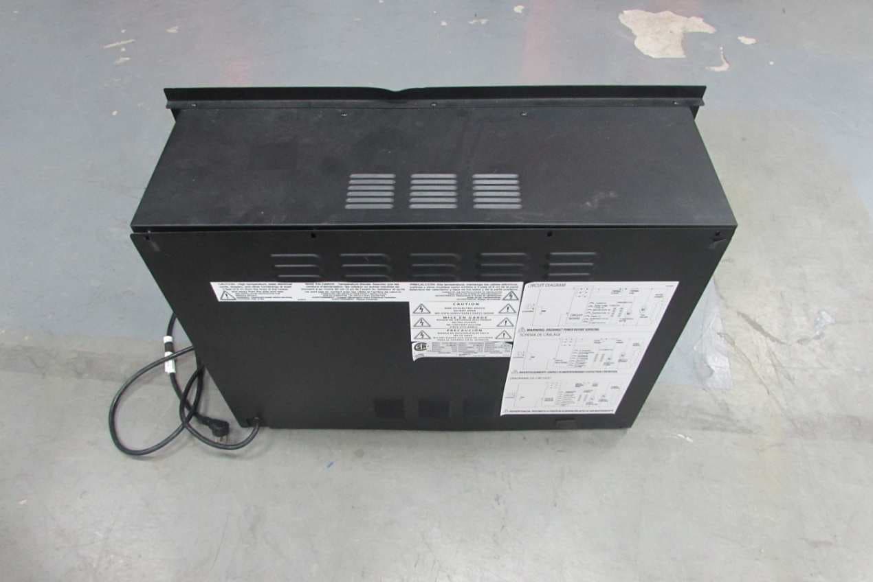
Click to zoom
Application Details
- Equipment Class
- DXX - Part 15 Low Power Communication Device Transmitter
- Date of Grant
- Aug 05, 2015
- Application Purpose
- Original Equipment
- Date of Application
- Aug 05, 2015
- Equipment Note
- LED Electric firebox with heater
- Frequency Range
- 2402.00000000 - 2480.00000000
- Company
- GHP Group, Inc.
- Country
- United States
Documents & Files
Document Text
Text extracted from the exhibit documents filed with the FCC. Open a document above to read the original.
Users Manual
PLEASE READ THIS MANUAL BEFORE INSTALLING AND USING APPLIANCE WARNING! IF THE INFORMATION IN THIS MANUAL IS NOT FOLLOWED EXACTLY, AN ELECTRICAL SHOCK OR FIRE MAY RESULT CAUSING PROPERTY DAMAGE, PERSONAL INJURY OR LOSS OF LIFE. Retain this manual for future use. VEUILLEZ LIRE CE MANUEL AVANT L’INSTALLATION ET L’UTILISATION DE VOTRE FOYER AVERTISSEMENT! SI LES RENSEIGNEMENTS DE CE MANUEL NE SONT PAS EXACTEMENT SUIVIS, UN CHOC ÉLECTRIQUE OU UN INCENDIE PEUT SURVENIR, ET CAUSER DES DOMMAGES, DES BLESSURES OU LA PERTE DE VIE Conserver ce manuel pour une utilisation ultérieure. Français p. 18 | Español p. 3420-10-245 POR FAVOR LEA LAS INSTRUCCIONES DE INSTALACIÓN Y DE OPERACIÓN ANTES DE USAR ESTE CAJA DE FUEGO ¡ADVERTENCIA! SI NO SIGUE EXACTAMENTE LA INFORMACIÓN EN ESTE MANUAL, PODRÍA RESULTAR EN CHOQUES ELÉCTRICOS O INCENDIO QUE PUEDEN CAUSAR DAÑOS A LA PROPIEDAD, LESIONES PERSONALES O LA PÉRDIDA DE LA VIDA. Guarde este manual para futuras referencias. 25-1000-001 / GLF-2505 / GLF-2507 USE AND CARE GUIDE | GUIDE D’UTILISATION ET D’ENTRETIEN | GUÍA DE USO Y CUIDADO ELECTRIC FIREBOXFOYER ÉLECTRIQUEHOGAR ELÉCTRICO IMPORTANT: SAVE THESE INSTRUCTIONS. IMPORTANT : CONSERVER CES INSTRUCTIONS. IMPORTANTE: GUARDE ESTAS INSTRUCCIONES. 2 Table of Contents Safety Information 1. Read all instructions before using this heater. 2. This heater is hot when in use. To avoid burns, do not let bare skin touch hot surfaces. If provided, use handles when moving this heater. Keep combustible materials, such as furniture, pillows, bedding, papers, clothes, and curtains at least 3 feet (0.9 meters) from the front of the heater and keep them away from the sides and rear. 3. Extreme caution is necessary when any heater is used by or near children or invalids and whenever the heater is left operating and unattended. 4. Always unplug heater when not in use. 5. Do not operate any heater with a damaged cord or plug or after the heater malfunctions, has been dropped or damaged in any manner. Return heater to authorized service facility for examination, electrical or mechanical adjustment, or repair. 6. Do not use outdoors. 7. This heater is not intended for use in bathrooms, laundry areas and similar indoor locations. Never locate heater where it may fall into a bathtub or other water container. 8. Do not run power cord under carpeting. Do not cover power cord with throw rugs, runners, or the like. Arrange power cord away from traffic area and where it will not be tripped over. 9. To disconnect heater, turn controls to off, then remove plug from outlet. 10. Connect to properly grounded outlets only. 11. Do not insert or allow foreign objects to enter any ventilation or exhaust openings as this may cause an electric shock or fire, or damage the heater. 12. To prevent a possible fire, do not block firebox air intakes or exhaust in any manner. Do not operate firebox on soft surfaces, like a bed, where openings may become blocked. 13. A heater has hot and arching or sparking parts inside. Do not use in areas where gasoline, paint, or flammable liquids are used or stored. 14. Use this heater only as described in this manual. Any other use not recommended by the manufacturer may cause fire, electrical shock, or injury to persons. 15. Avoid the use of an extension cord because of the risk of overheating the cord and the risk of fire. Extension cords are for temporary use only. If an extension cord must be used, it must be UL/CSA certified, rated at 15A (1875W), 125V maximum with 14 AWG minimum and constructed of two current carrying conductors with ground. A heavy duty extension cord with the shortest length possible for the connection is recommended and must not be longer than 50 ft. (15.2 m). Do not coil or cover the extension cord. 16. This electric fireplace is not designed for “zero” clearance wall and/or cabinet/millwork installations. Accessibility for servicing and maintenance must be possible without disturbing building structures and/or cabinet/millwork finishes. 17. SAVE THESE INSTRUCTIONS Table of Contents ...........................2 Safety Information ...........................2 User Instructions ............................3 Grounding Instructions ......................3 Locating Your Fireplace .....................3 Firebox Specifications .......................3 Electrical Connection .......................3 Remote Control ............................4 Warranty ...................................5 Pre-Installation ..............................6 Planning Installation ........................6 Tools Required. . . . . . . . . . . . . . . . . . . . . . . . . . . . . 6 Hardware Included ........................6 Package Contents .........................6 Installation .................................7 Mantel Installation ..........................7 Operation. . . . . . . . . . . . . . . . . . . . . . . . . . . . . . . . . . 8 Maintenance ..............................15 Glass information .........................15 Maintenance of Motors ....................15 Battery Replacement ......................15 Care and Cleaning. . . . . . . . . . . . . . . . . . . . . . . . . 15 Circuit Diagram ............................16 Troubleshooting ............................16 Service Parts ...............................17 3 Safety Information (continued) USER INSTRUCTIONS 1. Any repairs to this appliance should be carried out by qualified/authorized service personnel only. 2. Under no circumstances should this appliance be modified. Parts having to be removed for servicing must be replaced with original “OEM” (original equipment manufacturers) parts only. 3. This firebox is to be cleaned with a damp cloth (water) only. IMPORTANT: Always unplug the power cord before cleaning the unit. Do not use any abrasive cleaners on the unit. 4. Unplug this firebox when not in use. 5. Remove cardboard support from log set before activating firebox. To remove glass panel see “Installing the ember beds”. GROUNDING INSTRUCTIONS This heater is …
Text truncated - open the document above for the full version.
Block Diagram
Block Diagram Bluetooth Module Block Diagram Controlpanel LOGO Display board Bluetooth PCB MCU:CC2541 Oscillate: 32MHz; 32.768KHZ LOGSET LED Board Flame LED Board Main PCB MCU: SH79F0819M Oscillate 11.0596MHz AC POWER :120V/60Hz
ID Label/Location Info
FCC ID Label
Internal Photos
Internal view (Remove back cover) Internal view (Remove back cover) Power circuit view Control part circuit view LED Light circuit view Bluetooth circuit Bluetooth Circuit remove module Bluetooth Module view Bluetooth Module view
Operational Description
CC2541 www.ti.comSWRS110D– JANUARY2012– REVISEDJUNE2013 2.4-GHzBluetooth™lowenergyandProprietarySystem-on-Chip CheckforSamples:CC2541 1 FEATURES 23 •RF –High-PerformanceandLow-Power8051 MicrocontrollerCoreWithCodePrefetch –2.4-GHzBluetoothlowenergyCompliant andProprietaryRFSystem-on-Chip–In-System-ProgrammableFlash,128-or 256-KB –Supports250-kbps,500-kbps,1-Mbps,2- MbpsDataRates–8-KBRAMWithRetentioninAllPower Modes –ExcellentLinkBudget,EnablingLong- RangeApplicationsWithoutExternalFront–HardwareDebugSupport End –ExtensiveBasebandAutomation,Including –ProgrammableOutputPowerupto0 dBmAuto-AcknowledgmentandAddress Decoding –ExcellentReceiverSensitivity(–94dBmat 1 Mbps),Selectivity,andBlocking–RetentionofAllRelevantRegistersinAll PerformancePowerModes –SuitableforSystemsTargetingCompliance•Peripherals WithWorldwideRadioFrequency –PowerfulFive-ChannelDMA Regulations:ETSIEN300328andEN300 –General-PurposeTimers(One16-Bit,Two 440Class2 (Europe),FCCCFR47Part15 8-Bit) (US),andARIBSTD-T66(Japan) –IRGenerationCircuitry •Layout –32-kHzSleepTimerWithCapture –FewExternalComponents –AccurateDigitalRSSISupport –ReferenceDesignProvided –BatteryMonitorandTemperatureSensor –6-mm× 6-mmQFN-40Package –12-BitADCWithEightChannelsand –Pin-CompatibleWithCC2540(WhenNot ConfigurableResolution UsingUSBorI 2 C) –AESSecurityCoprocessor •LowPower –TwoPowerfulUSARTsWithSupportfor –Active-ModeRXDownto:17.9mA SeveralSerialProtocols –Active-ModeTX(0dBm):18.2mA –23General-PurposeI/OPins –PowerMode1 (4-μs Wake-Up):270μA (21× 4 mA,2 × 20mA) –PowerMode2 (SleepTimerOn):1 μA –I 2 C interface –PowerMode3 (ExternalInterrupts):0.5μA –2 I/OPinsHaveLEDDrivingCapabilities –WideSupply-VoltageRange(2V–3.6V) –WatchdogTimer •TPS62730CompatibleLowPowerinActive –IntegratedHigh-PerformanceComparator Mode •DevelopmentTools –RXDownto:14.7mA(3-Vsupply) –CC2541EvaluationModuleKit –TX(0dBm):14.3mA(3-Vsupply) (CC2541EMK) Whitespace –CC2541MiniDevelopmentKit(CC2541DK- Whitespace MINI) Whitespace –SmartRF™Software Whitespace –IAREmbeddedWorkbench™Available Whitespace Whitespace •Microcontroller 1 Pleasebeawarethatanimportantnoticeconcerningavailability,standardwarranty,andusein criticalapplicationsof TexasInstrumentssemiconductorproductsanddisclaimerstheretoappearsattheendofthisdatasheet. 2Bluetoothis a trademarkofBluetoothSIG,Inc.. 3ZigBeeis a registeredtrademarkofZigBeeAlliance. PRODUCTIONDATAinformationis currentasofpublicationdate. Copyright© 2012–2013,TexasInstrumentsIncorporated ProductsconformtospecificationsperthetermsoftheTexas Instrumentsstandardwarranty.Productionprocessingdoesnot necessarilyincludetestingofallparameters. CC2541 SWRS110D– JANUARY2012– REVISEDJUNE2013www.ti.com SOFTWAREFEATURESCC2541WITHTPS62730 •Bluetoothv4.0CompliantProtocolStackfor•TPS62730isa 2-MHzStep-DownConverter Single-ModeBLESolutionWithBypassMode –CompletePower-OptimizedStack,•ExtendsBatteryLifetimebyupto20% IncludingControllerandHost •ReducedCurrentinAllActiveModes –GAP– Central,Peripheral,Observer,or •30-nABypassModeCurrenttoSupportLow- Broadcaster(IncludingCombination PowerModes Roles) •RFPerformanceUnchanged –ATT/ GATT– ClientandServer •SmallPackageAllowsforSmallSolutionSize –SMP– AES-128Encryptionand •CC2541Controllable Decryption –L2CAP DESCRIPTION –SampleApplicationsandProfiles TheCC2541isa power-optimizedtruesystem-on- chip(SoC)solutionforbothBluetoothlowenergyand –GenericApplicationsforGAPCentral proprietary2.4-GHzapplications.Itenablesrobust andPeripheralRoles networknodestobebuiltwithlowtotalbill-of-material –Proximity,Accelerometer,SimpleKeys, costs.TheCC2541combinestheexcellent andBatteryGATTServices performanceofaleadingRFtransceiverwithan –MoreApplicationsSupportedinBLE industry-standardenhanced8051MCU,in-system programmableflashmemory,8-KBRAM,andmany SoftwareStack otherpowerfulsupportingfeaturesandperipherals. –MultipleConfigurationOptions TheCC2541ishighlysuitedforsystemswhere –Single-ChipConfiguration,Allowing ultralowpowerconsumptionisrequired.Thisis ApplicationstoRunonCC2541 specifiedbyvariousoperatingmodes.Shorttransition timesbetweenoperatingmodesfurtherenablelow –NetworkProcessorInterfacefor powerconsumption. ApplicationsRunningonanExternal Microcontroller TheCC2541ispin-compatiblewiththeCC2540in the6-mm× 6-mmQFN40package,if theUSBis not –BTool– WindowsPCApplicationfor usedontheCC2540andtheI 2 C/extraI/Ois notused Evaluation,Development,andTest ontheCC2541.ComparedtotheCC2540,the CC2541provideslowerRFcurrentconsumption.The APPLICATIONS CC2541doesnothavetheUSBinterfaceofthe •2.4-GHzBluetoothlowenergySystems CC2540,andprovideslowermaximumoutputpower inTXmode.TheCC2541alsoaddsaHWI 2 C •Proprietary2.4-GHzSystems interface. •Human-InterfaceDevices(Keyboard,Mouse, RemoteControl) TheCC2541ispin-compatiblewiththeCC2533 RF4CE-optimizedIEEE802.15.4SoC. •SportsandLeisureEquipment TheCC2541comesintwodifferentversions: •MobilePhoneAccessories CC2541F128/F256,with128KBand256KBofflash •ConsumerElectronics memory,respectively. FortheCC2541blockdiagram,seeFigure1. 2SubmitDocumentationFeedbackCopyright© 2012–2013,TexasInstrumentsIncorporated ProductFolderLinks:CC2541 SFR bus SFR bus MEMORY ARBITRATOR 8051 CPU CORE DMA FLASH SRAM FLASH CTRL DEBUG INTERFACE RESET RESET_N P2_4 P2_3 P2_2 P2_1 P2_0 P1_4 P1_3 P1_2 P1_1 P1_0 P1_7 P1_6 P1_5 P0_4 P0_3 P0_2 P0_1 P0_0 P0_7 P0_6 P0_5 32.768-kHz CRYSTAL OSC 32-MHZ CRYSTAL OSC HIGH SPEED RC-OSC 32-kHz RC-OSC CLOCK MUX and CALIBRATION RAM USART 0 USART 1 TIMER 1 (16-Bit) TIMER 3 (8-bit) TIMER 2 (BLE LL TIMER) TIMER 4 (8-bit) AES ENCRYPTION and DECRYPTION WATCHDOG TIMER IRQ CTRL FLASH UNIFIED RF_PRF_N SYNTH MODULATOR POWER-ON RESET BROWN OUT RADIO REGISTERS POWER MGT. CONTROLLER SLEEP TIMER PDATA XRAM IRAM SFR XOSC_Q2 XOSC_Q1 DSADC AUDIO / DC DIGITAL ANALOG MIXED VDD (2 V–3.6 V) DCOUPL ON-CHIP VOLTAGE REGULATOR Link Layer Engine FREQUENCY SYNTHESIZER I 2 C DEMODULATOR RECEIVETRANSMIT OP- ANALOG COMPARATOR I/O CONTROLLER 1-KB SRAM Radio Arbiter FIFOCTRL SDA SCL CC2541 www.ti.comSWRS110D– JANUARY2012– REVISEDJUNE2013 Thisinteg…
Text truncated - open the document above for the full version.
Operational Description
Technical Description -1: :: : Part1:电源供电部分,采用120V/60Hz输入两组12V/0.5A输出变压器做电压转换,通过三端稳压器7810做10V转换 输出;通过三端稳压器78L05做5V转换; Power supply,use 120V/60Hz input,two 12V/0.5A output transformer as voltage converter,three terminal regulator 7810 as 10V transform output,three terminal regulator 78L05 as 5V transform output. Part2:T-FUSE检测电路,采用PC817光耦检测信号,当T-FUSE断开则进行切断加热保护并显示故障; T-FUSE detection circuit,use PC817 optocoupler detection signal,cut off the heat protection and display failure. Part3:加热、电机及led驱动电路,采用驱动IC ULN2003和三极管驱动; Heat/motor/LED drive circuit,use drive IC ULN2003 and triode drive. Part4:蓝牙模块通讯驱动电路,三极管实现5V和3.3V电平转换,实现5V供电的MCU与3.3V供电的蓝牙模块之间的 通讯; Bluetooth module communication drive circuit,use triode as 5V and 3.3V level conversion,achive the communication between 5V power supply MCU and 3.3V power supply bluetooth module. Part5:通过MCU:SH79F0819M检测和驱动各部分电路; SH79F0819M detection and drive each circuit through MCU. Part6:NTC传感器检测电路,检测环境温度,转换为电平信号给MCU; NTC sensor detecioncircuit,detectenviromenttemperature,convert to level signal to MCU. Part7:按键显示接口,连接电源板和按键显示板接口; Key display interface,connect power panel and key display interface. Technical Description -2: :: : Part8:蓝牙模块电路,蓝牙模块接收到手机的命令后,通过UART串口把数据发给MCU,MCU做相应的指令动作,并 反馈状态给模块,模块收到状态后转给手机; Bluetooth module circuit,when bluetooth module receives the command of mobilephone,it will send the data to MCU by UART serial port,MCU acts accordingly and response to module,module pass info to mobilephone. Part9:商标LOGO显示电路,; Logo display circuit. Part10:按键显示板,通过驱动IC1642进行对数码管显示驱动和按键扫描;接收头接收到遥控器发出的红外指令后转给 MCU; Button display board,start nixie tube display driver and key scan through driver IC1642;after the receiver receives infrared command from remote control,then pass to MCU. Part11:火焰灯LED显示电路; The flame lamp LED display circuit. Part12:碳床灯LED显示电路; Log set lamp LED display circui
Operational Description
Add:Lierda Building,425 Dengyun Rd,Hangzhou, China Tel:0571-88800000 Fax:0571-89908519 LIERDA SCIENCE & TECHNOLOGY CO., LTD. Product Specification Product Name:P-series BLE Module Document version:V1.03 Add:Lierda Building,425 Dengyun Rd,Hangzhou, China Tel:0571-88800000 Fax:0571-89908519 Contents Chapter 1 Feature ........................................................................................................................................... 1 Chapter 2 Parameters ..................................................................................................................................... 2 Chapter 3 Product Specification .................................................................................................................... 3 3.1 boundary dimension ............................................................................................................................ 3 3.2 Pin Definition ...................................................................................................................................... 3 3.3 real product show ................................................................................................................................ 4 Chapter 4 Typical Circuit ............................................................................................................................... 5 Chapter 5 Pakge ............................................................................................................................................. 6 Appendix One BLE Profile brief introduction ............................................................................................. 8 Notes to users ................................................................................................................................................... 11 Add:Lierda Building,425 Dengyun Rd,Hangzhou, China Tel:0571-88800000 Fax:0571-89908519 Page 1 Chapter 1 Feature Lierda P-Series Low Power Consumption High performance Bluetooth transceiver Module is designed based on TI CC2541 chip. The Module has ceramic integrate antenna, and adopts SMT attachment interface. It has a complete open port which reduces hardware design difficulties and also provide high structural and software flexibility for users. The module has low power consumption, a compact size and have high resistance to disturbance. Based on different kinds of application firmware, Product Model offered as sheet 1-1. Sheet 1-1 Product Model Product Name Model number Remark P-series BLE Module-hardware only LSD4BT-P74MSTD1 No software, user development by themselves。 P-series BLE Module-unvarnished transmission master LSD4BT-P74MMST2 Lierda BLE application in unvarnished transmission,the master device P-series BLE Module-unvarnished transmission slave LSD4BT-P74MLSP2 Lierda BLE application in unvarnished transmission,the slave device P-series BLE Module-unvarnished transmission for ShengZheng H&T LSD4BT0478-01D0 Lierda BLE application in unvarnished transmission,ShnegZheng H&T Specific Lierda P-series Module can be applicable to many occasions: 2.4GHz low power consumption Bluetooth system PC, Tablet and other BLE Handheld devices (HID device, Remote Control) Consumers electronics such as physical, medical and so on Wireless network system such as Smart meters and data collection Add:Lierda Building,425 Dengyun Rd,Hangzhou, China Tel:0571-88800000 Fax:0571-89908519 Page 2 Chapter 2 Parameters Sheet 2-1 Module Parameters Item Parameters Remarks Supply voltage 2.0 ~ 3.6 V(classic 3.3V) Low power may cause failure. Over power may damage device frequency 2402 ~ 2480 MHz Power consumption Emitting ≤ 25 mA @0dBm , MCU-32MHz Receiving ≤ 25 mA @MCU-32MHz Sleep ≤ 1 uA Sleep Mode Emission power (-23dBm ~0dBm) ±1dBm Programmable Operating ambient temperature range -20°C ~ 70 °C Storage temperature range -40°C ~ 85 °C channel 40 3 broadcast channel and 37 data transmission channel modulation format GFSK Aaptive frequency hopping Communication BLE standrd I/O Control 0 ~ VCC Air baud rate 1Mbps Transmission distance 20m Open and visual environment 60% RH、25°C 10m Barrier Free in Cross space Port type 1.27 mm Single row* 3 SMT gain of Antenna 2 dBi (Typical) Application Refer the appendix one Operating Humidity range 30%~70% All the parameters are tested at the environment of 25°C±3°C Transmission distance is affected by the temperature and humidity and is only for reference Add:Lierda Building,425 Dengyun Rd,Hangzhou, China Tel:0571-88800000 Fax:0571-89908519 Page 3 Chapter 3 Product Specification 3.1 outline dimensional drawing Figure 3-1 Module dimension and interface *Size tolerance which not be marked according to GB/T1804-m standards 3.2 Pin Definition Sheet 3-1 Pin Definition Number Name 功能 备注 1 ANT Be used for the external antenna Selected through capacitance 2 VCC Power IN 3 GND Ground All Grounding needed 4 P0.0-P0.7 I/O port 5 P1.0-P1.7 I/O port Add:Lierda Building,425 Dengyun Rd,Hangzhou, China Tel:0571-88800000 Fax:0571-89908519 Page 4 Number Name 功能 备注 6 P2.1-P2.2 I/O port 7 SCL_UP I2C port SCL 8 SDA_UN I2C port SDA 10 REST_N Reset Active Low More detail for the IO type and load capacity could be found in “CC2540/41 System-on-Chip Solution for 2.4-GHz Bluetooth® low energy Applications”, this module lead them directly. P – Series Module did not set Reset-cicuit for the REST_N pin. please refer to the chapter 4 when you design. 3.3 real product show 图3-1 real product *Pictures are for reference only, there may be differences according to different versions Add:Lierda Building,425 Dengyun Rd,Hangzhou, China Tel:0571-88800000 Fax:0571-89908519 Page 5 Chapter 4 Typical Circuit ANT 1 GND 2 P2.2 3 P2.1 4 GND 5 P1.7 6 P1.6 7 SCL_UP 8 SDA_UN 9 GND 10 VUSB_NC 11 P1.5 12 P1.4 13 P1.3 14 P1.2 15 P1.1 16 GND 17 VCC 18 P1.0 19 P0.7 20 P0.6 21 P0.5 22 P0.4 23 P0.3 24 GND 25 P0.2 26 P0.1 27 P0.0 28 RESET_N 29 * P 系列 BLE 模块 VCC GND GND GND GND 47K 1nF 2.7K GND VCC Figure 4-1 Ty…
Text truncated - open the document above for the full version.
Schematics
12345678 A B C D 87654321 D C B A Title NumberRevisionSize A3 Date:21-Jul-2015Sheet of File:C:\Documents and Settings\Administrator\桌面\工作\项目\K系列\K2\FD30.40K2\ MyDesi gnDrawn By: C15 104 RY ZN1 10K271 RLY2 10A RLY3 10A 12V FUSE C21 102 C9 104 MOTO-P HEAT2-P FAN-PHEAT1-P GND 5V KCOM CLK DATA R40 1K HEAT2 MOTO HEAT1 ACN NTC-P C20 102 R38 10K 1% 5V R39 1K MOTO-P HEAT1-P 13V HEAT1 ACL 输入:120VAC/60Hz 5V RLY1 10A 1 1 2 2 NTC2 水滴型NTC 1 1 2 2 3 3 4 4 5 5 6 6 CN2 CN5A ACN ACL CX1 0 . 1uF - K - 275 VAC NTC 显示部分 LED灯接线模块 1B 1 2B 2 3B 3 4B 4 5B 5 6B 6 7B 7 E 8 COM 9 7C 10 6C 11 5C 12 4C 13 3C 14 2C 15 1C 16 IC3 ULN2003 继电器驱动部分 RLY4 10A HEAT2 HEATER1 HEATER2 HTER1 HTER2 MOTO FAN MCU TXS/SEG10/P2.1 1 FLT/SEG14/P2.5 2 PWM/SEG19/P0.2 3 XTALX2/INT2/P0.6 4 XTALX1/INT3/P0.7 5 GND 6 XTAL1/P5.0 7 XTAL2/P5.1 8 VDD 9 AN1/INT43/P4.3 10 AN2/INT42/P4.2 11 AN1/INT41/P4.1 12 AN0/INT40/P4.0 13 AN7/P3.7 14 P3.5/AN5 15 P3.3/COM4/LED_C4 16 P3.2/COM3/LED_C3 17 P3.1/COM2/LED_C2 18 P3.0/COM1/LED_C1 19 P1.0/SEG1/LED_S1/TDO 20 P1.1/SEG2/LED_S2/TMS 21 P1.2/SEG3/LED_S3/TDI 22 P1.3/SEG4/LED_S4/TCK 23 P1.4/SEG5/LED_S5 24 P1.5/SEG6/LED_S6 25 P1.6/SEG7/LED_S7 26 P1.7/SEG8/LED_S8 27 P20/SEG9/RXD 28 IC5 SH79F0819 B1 B2 Y1 B1-P B2-P Y1-P HEAT2-P ACN WK2 REC R37 150R 1 1 2 2 BGY1 XHB-2A BGY2-P BGY2 BGY1-P BGY2-P NTC NTC-P KCOM CLK DATA C12 104 R2 47R-1206 B2 Y2 B1 Y1 12V 3V3 RXD_3V TXD_3V GND R32 4K7 3V3 C16 101 TXD_5V RXD_3V Q3 s8050 R31 4K7 TXD_5VRXD_5V FAN D9 4148 12V FAN-P Q2 S8050 R28 4K7 R27 4K7 Y2Y2-P B1-P B2-P Y1-P Y2-P IO-C SW1-P SW2-P REC-P REC-P ZERO BUZ XTLA1 11.0592M C13 20P C14 20P 1 2 3 CN4 XH-3A 1 2 3 CN3 XHB-3A红色 连接到前灯板 连接到后灯板 R41 4.7k R42 4.7k C22 101 Q5 8050 3V35V TXD_3V RXD_5V 5V R46 4.7k R43 4.7k Q7 8050 3V35V CONN CONN-IN R44 4.7k R45 4.7k C24 101 Q6 8050 3V35V MODE MODE-IN MODE-IN 1 2 3 4 5 6 BLUE XHB-6A红色 CONN MODE 1 1 2 2 MOTO1 CN2 MAX 1 1 2 2 FAN1 CN2 MAX ACN ACN 1 1 3 3 4 4 5 5 6 6 7 7 8 8 9 9 BYQ D5 IN4007 D10 IN4007 D6 IN4007 D7 IN4007 D1 IN4007 D4 IN4007 D3 IN4007 D2 IN4007 EC1 25V/1000UF INOUT GND U3 IC7810 EC2 25V/1000UF R4 1K INOUT GND IC4 IC7805 EC3 16V/220UF R15 10K GND 5V 3 2 1 IN OUT GND U2 LM1117-3.3V 3V3 C11 104 EC8 220u/16V R25 10K R5 47R R6 47R 10V ACN1 R3 47R-1206 连接到蓝牙小板 连接到背光源小板 CONN-IN EC4 25V/1000UF 13V R1 4K7 1 3 45 67 D8 T-FUSE R16 1 T-FUSE1 C1 R18 5V R19 ZERO A 1 K 2 C 4 E 3 IC2 ACL 过零检测部分 R16 2 Power circuit 12345678 A B C D 87654321 D C B A Title NumberRevisionSize A3 Date:21-Jul-2015Sheet of File:C:\Documents and Settings\Administrator\桌面\工作\项目\K系列\K2\FD30.40K2\ MyDesi gnDrawn By: Q0 1 Q1 2 Q2 3 Q3 4 Q4 5 Q5 6 Q6 7 Q7 8 C1 9 C2 10 C3 11 C4 12 CLK 13 DATA 14 VDD 15 GND 16 IC1 1642 DP C G B A E D F R1 150R R2 150R R7 150R R8 150R R9 150R R10 150R R11 150R R12 150R A B C D E F G DP LA LB LC LD LE LF LG LDP CO M1 LG CO M2 CO M3 LCLELDP LFLA -1 LD COM1 COM2 COM3 COM4 C1 104 C5 10uF/16V 5V DATA CLK 1 2 3 4 5 6 CN1 连接 电源板 GND 5V CLK DATA R4 4K7 R3 4K7 C4 101 C3 101 5V 显示板 A A K K KEY4 KEY6 LC LD KEY7 A A K K KEY1 KEY3 LE LF LG A A K K KEY5 POWER1 LDP LBCOM4 Y1 5mm黄发金黄 Y2 5mm黄发金黄 Y3 5mm黄发金黄 RY1 1R-1/4W 10V Y1 后灯板,插件 1 2 3 CN1 连接 电源板 B 10V KEY2 LA REC REC C2 1045V KEY2 KEY3 KEY4 KEY6 KEY7 KEY1 KEY5 R16 1K R5 1K R14 1K R6 1K R13 1K R17 1K R15 1K KCOM R18 4K7 KA KG KC KD KE KF KDP A G C D E F DP KCOM LB REC Y B1 5mm蓝色 B2 5mm蓝色 B3 5mm蓝色 RB1 1R-1/4W 10V B LED1 背光源 2 1 CN1 JC2.5-2P 背光源小板 EDDPCGGE B SH BA F A QI 88:88 127 612345 891011 SEG 三位数码管 R19 150R LA-1 COM4 Y4 5mm黄发金黄 Y5 5mm黄发金黄 Y6 5mm黄发金黄 RY2 1R-1/4W Y1 Y7 5mm黄发金黄 Y8 5mm黄发金黄 Y9 5mm黄发金黄 RY3 1R-1/4W Y1 Y10 5mm黄发金黄 Y11 5mm黄发金黄 Y12 5mm黄发金黄 RY4 1R-1/4W Y1 B1 5mm蓝色 B2 5mm蓝色 B3 5mm蓝色 RB1 1R-1/4W B B1 5mm蓝色 B2 5mm蓝色 B3 5mm蓝色 RB1 1R-1/4W B B1 5mm蓝色 B2 5mm蓝色 B3 5mm蓝色 RB1 1R-1/4W B Y1 5050橙灯 Y2 5050橙灯 Y3 5050橙灯 RY1 150R 10V Y1 Y4 5050橙灯 Y5 5050橙灯 Y6 5050橙灯 RY3 150R Y1 Y7 5050橙灯 Y8 5050橙灯 Y9 5050橙灯 RY5 150R Y1 Y10 5050橙灯 Y11 5050橙灯 Y12 5050橙灯 RY7 150R Y1 Y13 5050橙灯 Y14 5050橙灯 Y15 5050橙灯 RY10 150R Y1 Y16 5050橙灯 Y17 5050橙灯 RY11 300R-1/4W Y1 RY2 150R RY12 300R-1/4W RY4 150R RY6 150R RY8 150R RY9 150R B1 5050蓝灯 B2 5050蓝灯 B3 5050蓝灯 RB1 100R 10V B1 B4 5050蓝灯 B5 5050蓝灯 B6 5050蓝灯 RB2 100R B1 B7 5050蓝灯 B8 5050蓝灯 B9 5050蓝灯 RB3 100R B1 B10 5050蓝灯 B11 5050蓝灯 B12 5050蓝灯 RB4 100R B1 B13 5050蓝灯 B14 5050蓝灯 B15 5050蓝灯 RB5 100R B1 B16 5050蓝灯 B17 5050蓝灯 RB02 220R B1 后灯板,插件 1 2 3 CN3 ZH-3AW[连接电源板] B1 10V Y1 1234 SW ZH-4AW [连接电源板] 5V S W2 S W1 123 CN1 ZH-3AW[连接霍尔开关] 123 CN2 ZH-3AW[连接霍尔开关] 5V GNDS W1 5V GNDS W2 霍尔开关预留 1 2 3 4 5 6 7 8 9 10 111213141516171819 20 21 22 23 24 25 26 27 28 29 BLE 1 2 3 4 5 6 CN1 3.3V C1 104 GND RXD TXD CONN MODE R2 4k7 C2 102 蓝牙模块小板 8 9 10 11 12 Peripheral circuit of bluetooth Module uses 3.3V power ,before into the module must pass the filter capacitor.uses two kinds of crystal 32.768k and 32M.RF signal transmitted by the external filter ceramic antenna or an external antenna out;The Module has SMT attachment interface. Bluetooth Module Circuit: The component value of circuit diagram of the Bluetooth module refer to module FCC ID: N8NLSD4BTP74MSTD1
Test Report
Report No.: 150526030GZU-001 Issued: 2015-7-27 FCC ID: 2AEZS-25-1000-001 Page 2 of 29 CONTENT TEST REPORT ........................................................................................................................................................... 1 CONTENT ................................................................................................................................................................... 2 1.0 Summary of Test............................................................................................................................................ 3 2.0 General Description ....................................................................................................................................... 4 2.1 Product Description ........................................................................................................................ 4 2.2 Related Submittal(s) Grants ........................................................................................................... 5 2.3 Test Methodology .......................................................................................................................... 5 2.4 Test Facility .................................................................................................................................... 5 3.0 System Test Configuration ............................................................................................................................ 6 3.1 Justification .................................................................................................................................... 6 3.2 EUT Exercising Software ............................................................................................................... 7 3.3 Special Accessories ........................................................................................................................ 7 3.4 Measurement Uncertainty .............................................................................................................. 7 3.5 Equipment Modification ................................................................................................................. 7 3.6 Support Equipment List and Description ....................................................................................... 7 4.0 Measurement Results ..................................................................................................................................... 8 4.1 Antenna Requirement: .................................................................................................................... 8 4.2 Occupied Bandwidth: ..................................................................................................................... 9 4.7 Radiated Emission ........................................................................................................................ 13 4.8 Band Edges Requirement ............................................................................................................. 23 4.9 Conducted Emissions at Mains Terminals ................................................................................... 26 10.0 Test Equipment List ..................................................................................................................................... 29 Report No.: 150526030GZU-001 Issued: 2015-7-27 FCC ID: 2AEZS-25-1000-001 Page 3 of 29 1.0 Summary of Test TEST TEST REQUIREMENT TEST METHOD RESULT Antenna Requirement FCC PART 15 C Section 15.203 FCC PART 15 C Section 15.203 PASS Occupied Bandwidth FCC PART 15 C section 15.215(c) ANSI C63.10: Clause 6.9 PASS Radiated Emission FCC PART 15 C section 15.249 (a), (d) ANSI C63.10: Clause 6.4, 6.5 & 6.6 PASS Band Edges Measurement FCC PART 15 C section 15.249 (d) ANSI C63.10: Clause 6.10 PASS Conducted Emissions at Mains Terminals FCC PART 15 C section 15.207 ANSI C63.10: Clause 6.2 PASS Remark: N/A: not applicable. Refer to the relative section for the details. EUT: In this whole report EUT means Equipment Under Test. Tx: In this whole report Tx (or tx) means Transmitter. Rx: In this whole report Rx (or rx) means Receiver. RF: In this whole report RF means Radio Frequency. ANSI C63.10: the detail version is ANSI C63.10:2013 in the whole report. Report No.: 150526030GZU-001 Issued: 2015-7-27 FCC ID: 2AEZS-25-1000-001 Page 4 of 29 2.0 General Description 2.1 Product Description Operating Frequency 2402 MHz to 2480 MHz Type of Modulation: GFSK Number of Channels 40 Channels Channel Separation: 2 MHz Antenna Type Integral Antenna gain: 2 dBi Speciality: Bluetooth 4.0 with BLE (Bluetooth Low Ener…
Text truncated - open the document above for the full version.
Contact Information
Applicant
Mary Flynn(Vice President Product Development)
Technical Contact
Intertek Testing Services Shenzhen Ltd. GuangzhouSky Zhu
[email protected]86-20-82139691
Block E, No 7-2 Guang Dong Software Science Park · Guangzhou, Guangdong Provice · China
Test Firm
Intertek Testing Services Shenzhen Ltd.strong yao
[email protected]8628219940
Technical Specifications
| # | Rule Parts | Frequency Range | Power Output |
|---|---|---|---|
| 1 | 15C | 2.40 GHz - 2.48 GHz | - |