2AF6C-CS-1900PACTIVE BLUETOOTH CEILING SPEAKERS
Azlan Logistics Limited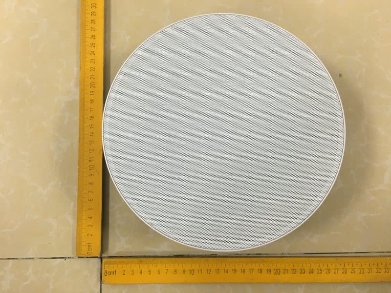
Click to zoom
Application Details
- Equipment Class
- DTS - Digital Transmission System
- Date of Grant
- Jul 24, 2020
- Application Purpose
- Original Equipment
- Date of Application
- Jul 24, 2020
- Equipment Note
- ACTIVE BLUETOOTH CEILING SPEAKERS
- Frequency Range
- 2402.00000000 - 2480.00000000
- Company
- Azlan Logistics Limited
- Country
- United Kingdom
Documents & Files
Document Text
Text extracted from the exhibit documents filed with the FCC. Open a document above to read the original.
Users Manual
1 CS-1900P_manual_en.doc CS-1900P POWERED SPEAKERS OWNERS MANUAL www.visionaudiovisual.com/cs-1900p 2 CS-1900P_manual_en.doc DECLARATION OF CONFORMITY Where applicable Vision products are certified and comply with all known local regulations to a ‘CB Certification’ standard. Vision commits to ensure all products are fully compliant with all applicable certification standards for sale in the EU and other participating countries. The product described in this owner manual is in compliance with RoHS (EU directive 2002/95/EC), and WEEE (EU directive 2002/96/EC) standards. This product should be returned to the place of purchase at the end of its useful life for recycling. WARNINGS CAUTION: TO REDUCE THE RISK OF ELECTRIC SHOCK DO NOT REMOVE COVER (OR BACK). NO USER-SERVICEABLE PARTS INSIDE. REFER SERVICING TO QUALIFIED SERVICE PERSONNEL. The lightning flash with arrowhead symbol, within an equilateral triangle, is intended to alert the user to the presence of uninsulated “dangerous voltage” within the product’s enclosure that may be of sufficient magnitude to constitute a risk of electric shock to persons. The exclamation point within an equilateral triangle, is intended to alert the user to the presence of important operating and maintenance (servicing) instructions in the literature accompanying the appliance. WARNING: TO REDUCE THE RISK OF FIRE OR ELECTRIC SHOCK, DO NOT EXPOSE THIS APPLIANCE TO RAIN OR MOISTURE. All products are designed and imported into the EU by ‘Vision’ who is wholly owned by ‘Azlan Logistics Ltd.’, Registered in England Nr. 04625566 at Lion House, 4 Pioneer Business Park, Clifton Moor, York, YO30 4GH. WEEE Registration: GD0046SY DECLARATION OF ORIGIN Vision products are made in the People’s Republic of China (PRC). 3 CS-1900P_manual_en.doc USE ONLY DOMESTIC AC OUTLETS Connecting the unit to an outlet supplying a higher voltage may create a fire hazard. HANDLE THE POWER CORD WITH CARE Do not disconnect the plug from the AC outlet by pulling the cord; always pull the plug itself. Pulling the cord may damage it. If you do not intend to use your unit for any considerable length of time, unplug the unit. Do not place furniture or other heavy objects on the cord, and try to avoid dropping heavy objects on it. Do not tie a knot in the power cord. Not only could the cord be damaged, but a short circuit could also be caused with a consequent fire hazard. PLACE OF INSTALLATION Avoid installing this product under the following conditions: • Moist or humid places • Places exposed to direct sunlight or close to heating equipment • Extremely cold locations • Places subject to excessive vibration or dust • Poorly ventilated places Do not expose this product to dripping or splashing. DO NOT PLACE OBJECTS FILLED WITH LIQUIDS ON OR NEAR THIS PRODUCT! MOVING THE UNIT Before moving the unit, be sure to pull out the power cord from the AC outlet and disconnect the interconnection cords with other units. WARNING SIGNS If you detect an abnormal smell or smoke, turn this product off immediately and unplug the power cord. Contact your reseller or Vision. PACKAGING Save all packing material. It is essential for shippi ng in the event the unit ever needs repair. IF ORIGINAL PACKAGING IS NOT USED TO RETURN THE UNIT TO THE SERVICE CENTRE, DAMAGE IN TRANSIT WILL NOT BE COVERED BY WARRANTY. WATTS The most consistent standards for measuring watts are “Program Power” and “RMS” because these measure average sustained levels. Where loudspeakers have integrated amplifiers, then load (resistance, measured in ohms) is known so the wattage rating is fixed. HUMIDITY These loudspeakers are not waterproof and are not designed to work in high humidity areas. 4 CS-1900P_manual_en.doc CONNECTIVITY Master Loudspeaker Power Input Line-level Input 2-phono and Minijack summed IR Receiver Switch Speaker Output Daisy-chain IN 3.5mm minijack Daisy-chain OUT 3.5mm minijack RS-232 9-pin d-sub SW2 Button For BT setup Mini USB for BT Setup 5 CS-1900P_manual_en.doc SPEAKER CABLE Speaker cable is included to connect master to slave. You can use other speaker cable; it must be unshielded with a gauge of no less than 0.75mm. WARRANTY VOID IF YOU USE UNSUITABLE SHIELDED CABLE E.G. PHONO OR MINIJACK CABLE. IR RECEIVER SWITCH FRONT - IR receiver on front active. Remote control can be used normally REAR –IR receiver on rear active. Front IR receiver disabled. Suitable for control system integration. OFF – both front and rear receivers, and line-le vel inputs are disabled. Use in permanent daisy- chain mode. DAISY-CHAIN Connect multiple sets together in larger rooms – no limit to number of sets. The first set in chain is “master set” which switches inputs and adjusts volume. Do not connect a laptop or phone directly to the daisy-chain input. BLUETOOTH AUTO-SWITCHING Use BT PRIORITY on remote control to enable auto-switching from line-level input to Bluetooth input when a Bluetooth device is paired. With BT PRIORITY on , When a BT device is unpaired the speakers will switch back to line-level input. 6 CS-1900P_manual_en.doc AUTO STANDBY The loudspeakers go into standby after 10 minutes of inactivity. • Bluetooth device NOT PAIRED when it goes into standby: o wake up when you pair a device or play audio though the line-level input. • Bluetooth device PAIRED when it goes into standby: o if BT input was selected: only Bluetooth source will wake them up. o If line-level input was selected: only line-le vel input will wake them up. STATUS INDICATORS BLUE – Bluetooth input Flashing slowly: Bluetooth is in pairing mode On: Device paired YELLOW – Line-level input On: cable input selected RED LED –Standby Flashing slowly: mute activated Flashing quickly: IR from remote control being received On: in standby 7 CS-1900P_manual_en.doc REMOTE CONTROL 1. POWER On / Off 2. INPUT SELECT Bluetooth / Line-level (cabled) input 3. RESET tone factory reset 4. BLUETOOTH PRIORITY auto-switches when BT device paired 5. AUTO STANDBY activate or deactivate 6.…
Text truncated - open the document above for the full version.
External Photos
FCC ID: 2AF6C-CS-1900P
ID Label/Location Info
Label Location On EUT Label Product Name: ACTIVE BLUETOOTH CEILING SPEAKERS Model No.: CS-1900P FCC ID: 2AF6C-CS-1900P This device complies with Part 15 of the FCC Rules. Operation is subject to the following two conditions: (1) This device may not cause harmful interference, and (2) This device must accept any interference received, including interference that may cause undesired operation.
Internal Photos
FCC ID: 2AF6C-CS-1900P ANT
Operational Description
version01 Azlan Logistics Limited Declaration concerning Antenna Specification It is hereby declared that the product Model No.: CS-1900P FCC ID : 2AF6C-CS-1900P fulfills the requirement in FCC test relating to the antenna type. The device specified above confirms to the FCC recommendations for internal antenna type(s) described below: Model No. of antenna: N/A Type of antenna: PCB Antenna BDR&EDR+BLE Gain of the antenna: 0 dBi Frequency range: 2402-2480MHz The mounting of the antenna is fixed to the radio module and no other antenna should be used. Company name: Azlan Logistics Limited Address: Redwood 2, Chineham Business Park, Crockford Lane, Basingstoke, Hampshire, RG24 8WQ United Kingdom City:Basingstoke, Hampshire ZIP / Postal code: RG24 Country:United Kingdom Place:United KingdomDate: 2020-07-23 Signature:
Test Report
Report No.: 18220WC00021202FCC ID: 2AF6C-CS-1900PPage 1 of 40 Code:AB-RF-05-a FCC TEST REPORT Client Name: Azlan Logistics Limited Address: Redwood 2, Chineham Business Park, Crockford Lane, Basingstoke, Hampshire,RG24 8WQ United Kingdom Product Name: ACTIVE BLUETOOTH CEILING SPEAKERS Date: Jul. 23, 2020 Shenzhen Anbotek Compliance Laboratory Limited Report No.: 18220WC00021202FCC ID: 2AF6C-CS-1900PPage 2 of 40 Code:AB-RF-05-a Contents 1. General Information ............................................................................................................................................... 5 1.1. Client Information ....................................................................................................................................... 5 1.2. Description of Device (EUT) ..................................................................................................................... 5 1.3. Auxiliary Equipment Used During Test ................................................................................................... 6 1.4. Description of Test Modes ........................................................................................................................ 6 1.5. List of channels ........................................................................................................................................... 6 1.6. Description Of Test Setup ......................................................................................................................... 7 1.7. Test Equipment List .................................................................................................................................... 8 1.8. Measurement Uncertainty ......................................................................................................................... 9 1.9. Description of Test Facility ........................................................................................................................ 9 2. Summary of Test Results ................................................................................................................................... 10 3. Conducted Emission Test ................................................................................................................................... 11 3.1. Test Standard and Limit .......................................................................................................................... 11 3.2. Test Setup .................................................................................................................................................. 11 3.3. Test Procedure .......................................................................................................................................... 11 3.4. Test Data .................................................................................................................................................... 11 4. Radiation Spurious Emission and Band Edge ................................................................................................ 16 4.1. Test Standard and Limit .......................................................................................................................... 16 4.2. Test Setup .................................................................................................................................................. 16 4.3. Test Procedure .......................................................................................................................................... 17 4.4. Test Data .................................................................................................................................................... 18 5. Maximum Peak Output Power Test .................................................................................................................. 26 5.1. Test Standard and Limit .......................................................................................................................... 26 5.2. Test Setup .................................................................................................................................................. 26 5.3. Test Procedure .......................................................................................................................................... 26 5.4. Test Data .................................................................................................................................................... 26 6. 6DB Occupy Bandwidth Test ............................................................................................................................. 29 6.1. Test Standard and Limit .......................................................................................................................... 29 6.2. Test Setup ............................................................................................................................... ................... 29 6.3. Test Procedure .......................................................................................................................................... 29 6.4. Test Data .................................................................................................................................................... 29 7. Power Spectral Density Test .............................................................................................................................. 32 7.1. Test Standard and Limit .......................................................................................................................... 32 7.2. Test Setup .................................................................................................................................................. 32 7.3. Test Procedure ...........................................................................................................…
Text truncated - open the document above for the full version.
Test Setup Photos
FCC ID: 2AF6C-CS-1900P Photo of Conducted Emission Measurement Photo of Radiation Emission Test
Contact Information
Applicant
Stuart Lockhart(General Manager)
Test Firm
Shenzhen Anbotek Compliance Laboratory LimitedJeff Zhu
Technical Specifications
| # | Rule Parts | Frequency Range | Power Output |
|---|---|---|---|
| 1 | 15C | 2.40 GHz - 2.48 GHz | 1.10 mW |
Other Applications from Azlan Logistics Limited
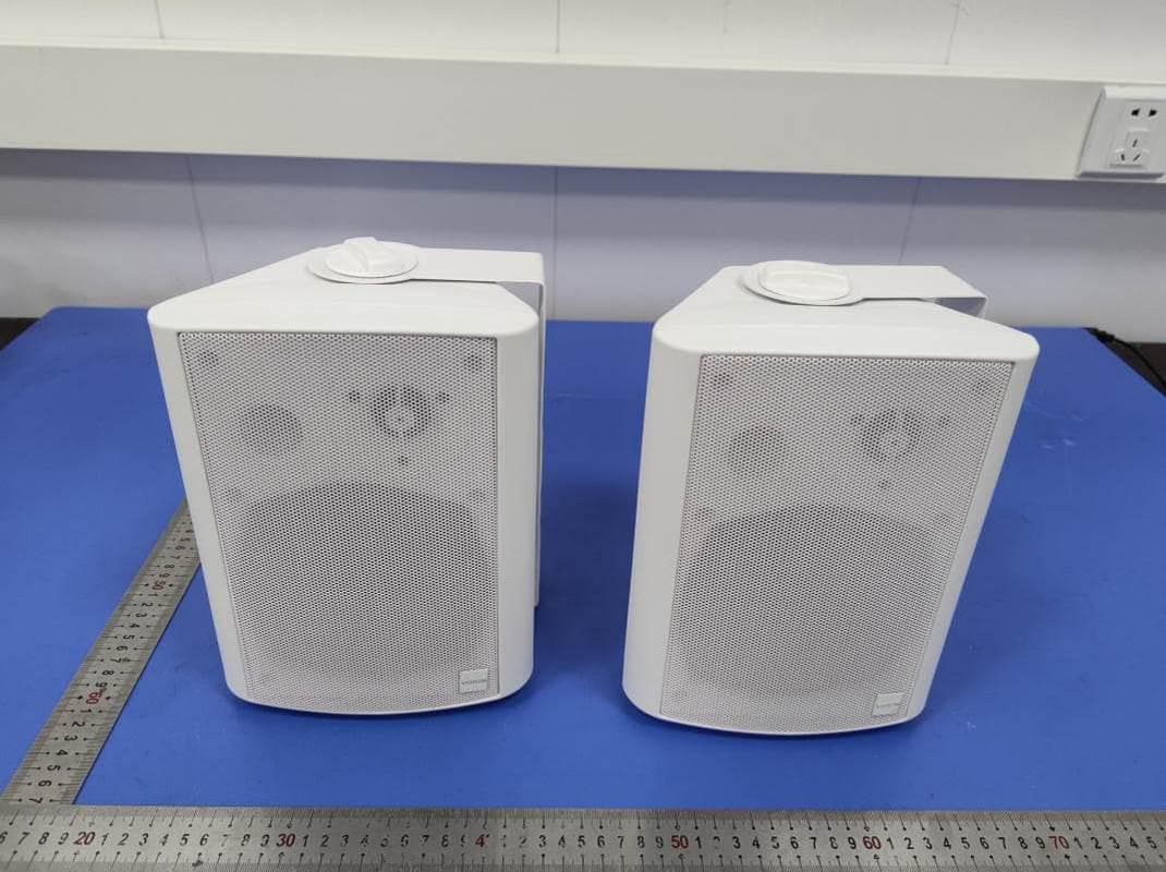
2AF6C-SP-1900P
Sep 23, 2020Active Loudspeakers
Equipment Class
DSS - Part 15 Spread Spectrum Transmitter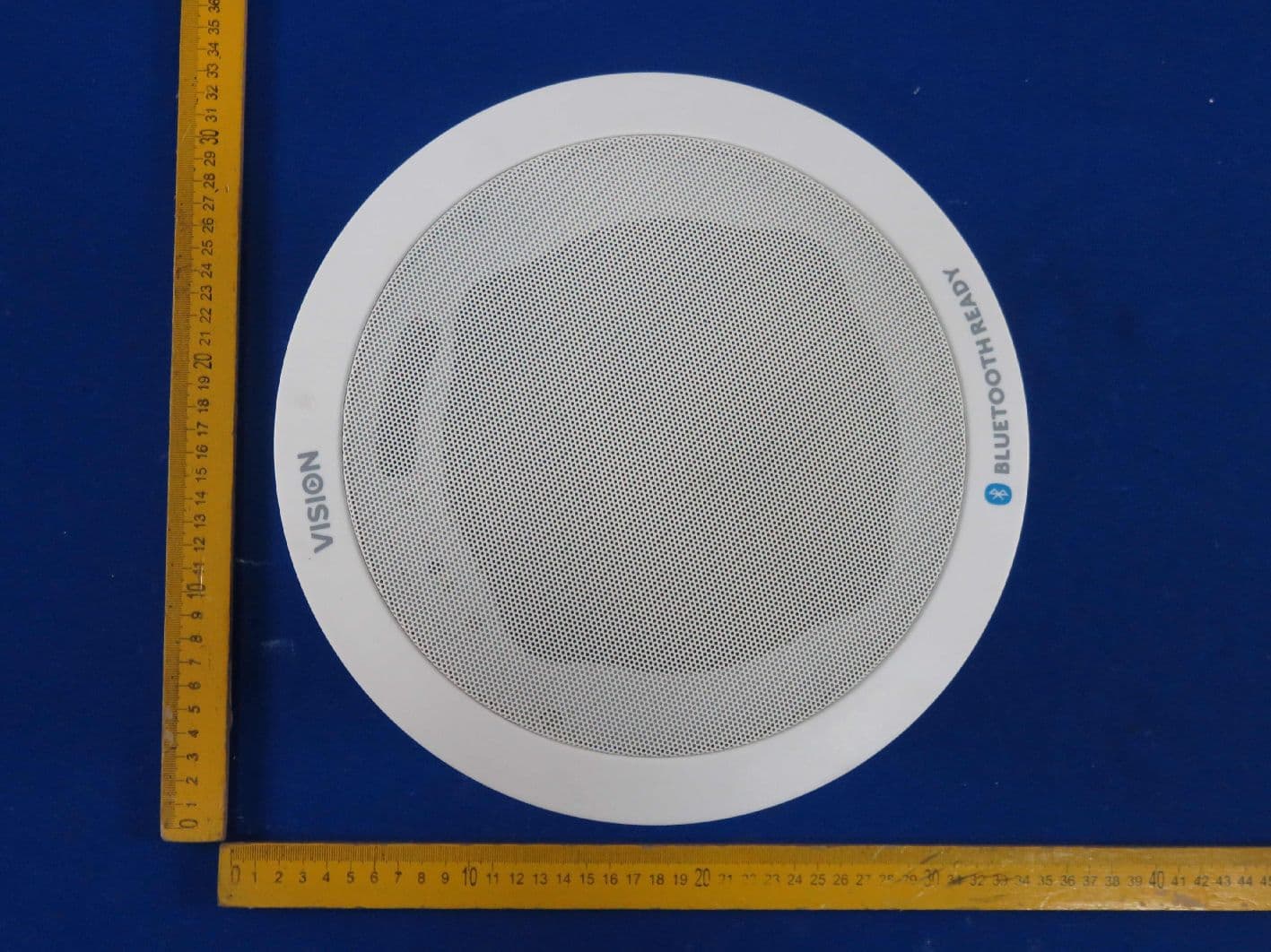
2AF6C-CS1600P
Nov 05, 2015Pair 60W Active Ceiling Loud Speaker
Equipment Class
DTS - Digital Transmission System