2AF6KBST1Vehicle Short Wave Radio - FM Transmitter
Expert Technology Studios, LLC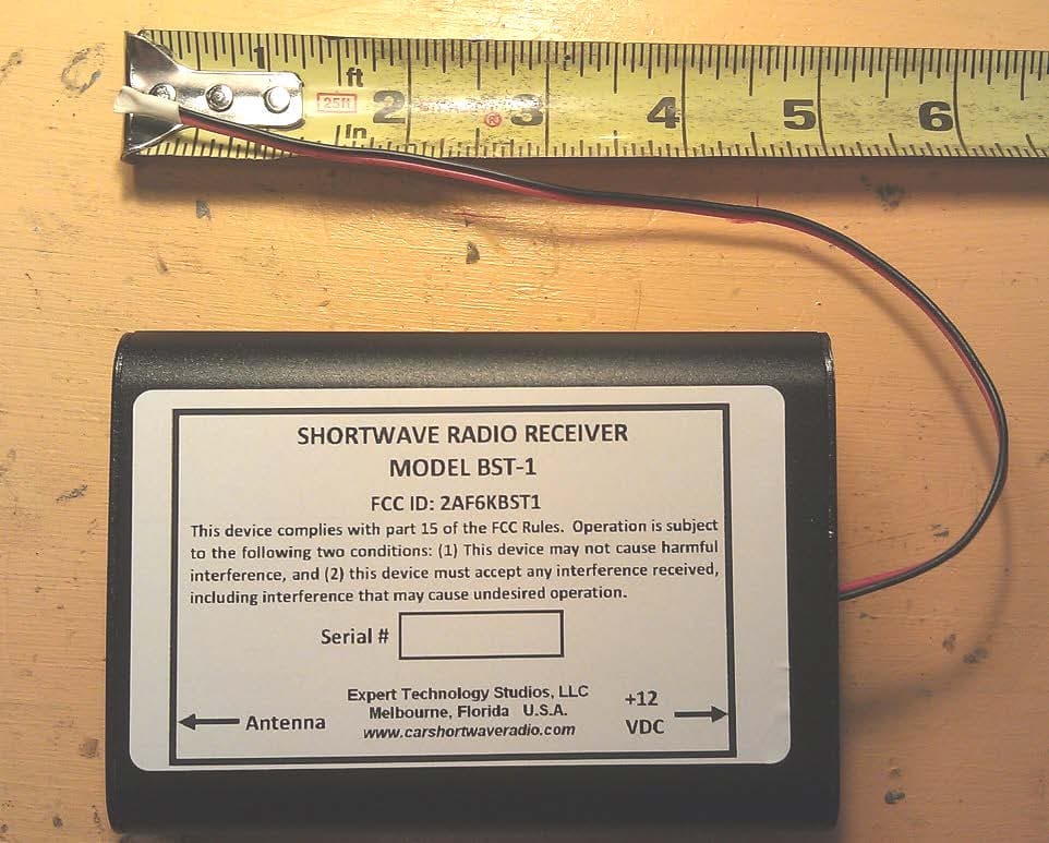
Click to zoom
Application Details
- Equipment Class
- DXX - Part 15 Low Power Communication Device Transmitter
- Date of Grant
- Dec 10, 2015
- Application Purpose
- Original Equipment
- Date of Application
- Dec 10, 2015
- Equipment Note
- Vehicle Short Wave Radio - FM Transmitter
- Frequency Range
- 88.30000000 - 88.90000000
- Country
- United States
Documents & Files
Document Text
Text extracted from the exhibit documents filed with the FCC. Open a document above to read the original.
Users Manual
BST-1 CAR SHORTWAVE RADIO FCC Part 15 ID: 2AF6KBST1 USERS MANUAL Expert Technology Studios, LLC Melbourne, FL 32901 Ver 16.0 2 CONTENTS 1 INTRODUCTION 4 1.1 WARNINGS, CAUTIONS, AND NOTES 4 1.2 DESCRIPTION OF EQUIPMENT 5 2 QUICK START INSTRUCTIONS 6 3 INSTALLATION 7 3.1 ANTENNA 7 3.2 COMPONENTS FOR I N S TA L L AT ION 8 3.3 INSTALLATION 8 3.4 INSTALLATION OF ANTENNA 8 4 ADVANCED OPERATING INSTRUCTIONS 9 4.1 KEY FOB FUNCTIONS 9 4.2 SUMMARY OF KEY FOB ACTION 10 4.2.1 TOP BUTTON 10 4.2.2 BOTTOM BUTTON 10 4.3 PRESET MODE 10 4.4 CHANGING TUNING DIRECTION 11 4.5 CHANGING MODES - TOGGLING BETWEEN TUNE AND PRESET MODES 11 4.6 TUNE MODE 11 4.7 SENSITIVITY CONTROL 12 4.8 RECEIVER BANDWIDTH 12 4.9 CHANGING FM TRANSMIT FREQUENCY 12 4.10 MORSE CODE ANNUNCIATION 12 4.11 QUICK TUNE TO WWV 12 4.12 STORING NEW PRESET CHANNELS 13 4.13 DELETING PRESET CHANNELS 13 4.14 S-METER 13 4.15 SLEEP MODE 14 4.16 TUNING RANGE 14 4.17 EMI REDUCTION 14 4.18 KEY FOB RANGE 14 5 TROUBLESHOOTING 16 6 SPECIFICATIONS 17 7 WARRANTY AND SERVICE INFORMATION 18 7.1 WARRANTY CONDITIONS 18 3 7.2 SHIPPING 19 7.3 WARRANTY EXCLUSIONS 19 7.4 SERVICE INFORMATION 20 8 APPENDIX A 21 4 1 INTRODUCTION 1.1 WARNINGS, CAUTIONS, AND NOTES Thank you for purchasing this product. To ensure safety, keep the following warnings and cautions in mind at all times when using this product. Observe all notes. Warning Inattention to proper operation of transport equipment (motor vehicle, ships, etc.) due to distractions while using this product may result in accidents resulting in death, serious injury, or significant property damage. Warning This is a consumer entertainment product and is not designed or manufactured for use in any situation in which malfunctions would threaten human life or result in injury. Nor is it designed or manufactured for use in other devices or systems requiring mission- critical quality and reliability. Warning This Device complies with Part 15 of the FCC rules. Operation is subject to the following two conditions: (1) This device may not cause harmful interference, and (2) this device must accept any interference received, including interference that may cause undesired operation. Warning Note: The Grantee is not responsible for any changes or modifications not expressly approved by the party responsible for compliance. Such modifications could void the user’s authority to operate the equipment. Caution Use only the automotive power cord that is supplied so that fuse protection is provided. Caution If left connected to an unswitched vehicle power source, the unit will enter a low current (20ma) standby mode after 2 hours. If used in this manner, insure that such standby current drain will not result in discharge of vehicle battery over long periods of inactivity. If in doubt, switch off power to the product by using the switch on the power plug. Note This product is not intended for repair by anyone other than the manufacturer. Note Reception of any specific shortwave station and general shortwave reception cannot be guaranteed due to uncertainties in ionospheric, atmospheric, and propagation conditions, internal and external 5 interference sources, antenna performance, and other parameters which can affect the overall signal to noise ratio of the desired received signal. Note The contents of this document and the specifications of the product are subject to change without notice due to product improvements. Note We have made every effort to confirm that all information provided in this document is correct and reliable. However, we take no responsibility for losses or damages incurred or infringements of patents or other rights resulting from use of the information. Note This document neither warrants nor authorizes the right to exercise intellectual property rights or any other rights belonging to Expert Technology Studios, LLC or third parties. Note No part of this document may be duplicated or reproduced in any form without prior consent from Expert Technology Studios, LLC. 1.2 DESCRIPTION OF EQUIPMENT The BST-1 is a shortwave receiver intended for vehicular use. It operates from a standard 11-14 V DC automotive electrical system. It has a 2-25 MHz AM shortwave receiver that tunes in 5 KHz channels and a built-in FCC Part 15 compliant FM transmitter. The FM transmitter allows the shortwave audio to be received by the vehicle’s FM radio and audio system. The tuned shortwave frequency and signal level will also be displayed on vehicle FM radios that have RDS capability. The BST-1 is tuned by wireless remote control using a FCC Part 15 compliant 433 MHz key fob (Produced by other suppliers) that communicates with a 433 MHz data receiver in the BST-1. 6 2 QUICK START INSTRUCTIONS Note: These instructions assume the BST-1 has been installed in accordance with the installation instructions in Section 3. 1. Make sure the car FM radio is operational and radio volume is set by first tuning in an FM station receivable in your area. 2. Tune your car FM radio to 88.5 MHz - this is the transmit frequency for the BST-1, as shipped. 3. If 88.5 MHz is not a strong local station in use in your area, you should hear noise or shortwave signals from the BST-1 and see a frequency displayed (if your FM radio has RDS capability). If you hear noise and see a SW frequency displayed, it is working. Note : Each time power is applied to the BST-1, your FM radio will display VER 0XXX where XXX is the current SW version. If you don't hear noise or shortwave signals from the BST-1 and don't see the BST-1 frequency information, go to step 5. 4. To operate the BST-1, momentarily press the bottom button and release. This starts the scanning of the 50 preset channels that are programmed as shipped from the factory (See Appendix A). The BST-1 will search and stop on an active channel. Momentarily pressing and releasing the bottom button will re-start the preset scanning to the next active station. For more advanced key fob functions, read the ADVANCED OPERATI…
Text truncated - open the document above for the full version.
Block Diagram
Block Diagram BST-1 SHORTWAVE RADIO FCC ID 2AF6LBST1 Expert Technology Studios, LLC Melbourne, FL 32901 November 4, 2015 2 INTRODUCTION The BST-1 is a shortwave receiver intended for vehicle use. It has a 2-25 MHz tunable AM shortwave receiver and a built-in FCC Part 15 compliant FM transmitter that provides the demodulated shortwave audio to the vehicle’s FM radio. The BST-1 is tuned by wireless remote control using an FCC Part 15 compliant 433.92 MHz key fob and a 433.92 MHz receiver contained within in the BST-1. BLOCK DIAGRAM Figure 1 shows the block diagram of the complete BST-1. More details on the 88.3 to 88.9 MHz FM transmitter portion are shown in Figure 2. Figure 1 – Block Diagram of BST-1 serial tuning data Audio serial tuning data Permanently attached 9” wire antenna Coax Antenna Input Permanently attached 9” wire antenna Super-regenerative Data receiver tuned to 433.92 MHz. Internal oscillator at 433.92 MHz. 2-25 MHz receiver. Internal 32.768 KHz crystal oscillator. This receiver is not subject to authorization FM Transmitter 88.3-88.9 MHz 32.798 KHz internal crystal reference See Figure 2 for details Transient power conditioning and +5 V regulator 8051 Microprocessor And Memory 2400 bit/sec data 11-14 VDC Vehicle power input 3 Figure 2 – Block Diagram of FM Transmitter
External Photos
Photographs BST-1 SHORTWAVE RADIO FCC ID 2AF6LBST1 Expert Technology Studios, LLC Melbourne, FL 32901 November 5, 2015 2 TOP VIEW 3 TOP VIEW BUILT IN ANTENNA FULLY EXTENDED 4 FRONT VIEW SHOWING ANTENNA CONNECTOR FOR 2-25 MHZ RECEIVER INPUT 5 REAR VIEW SHOWING DC POWER CONNECTOR AND PERMANENTLY ATTACHED ANTENNAS FOR FM TRANSMITTER AND 433 MHZ DATA RECEIVER 6 BOTTOM VIEW 7 LEFT SIDE VIEW 8 RIGHT SIDE VIEW
ID Label/Location Info
PREPRESS DIGITAL PROOF Processed and Reviewed by Trim line placed on top of your design will not show up on the final print-out. We strongly recommend that you read the comments made by prepress regarding issues found or fix-ups made on your file(if any). TRIM LINE SAFE ZONE FRONT SIDE ; PRODUCT SIZE: 4 in. X 2.5 in.
ID Label/Location Info
2 TOP VIEW
Internal Photos
9 TOP VIEW OF PWB ASSEMBLY 10 BOTTOM VIEW OF PWB ASSEMBLY 11 RIGHT END VIEW OF PWB ASSEMBLY ALSO SHOWS FRONT OF SUB-BOARD CONTAINING 433 MHZ RECEIVER 12 LEFT END VIEW OF PWB ASSEMBLY ALSO SHOWS REAR VIEW OF SUB-BOARD CONTAINING 433 MHZ RECEIVER 13 LEFT SIDE VIEW OF PWB ASSEMBLY RIGHT SIDE VIEW OF PWB ASSEMBLY 14 FRONT VIEW OF SUB-BOARD WITH 433 MHZ RECEIVER BACK VIEW OF SUB-BOARD OF 433 MHZ RECEIVER
Operational Description
Circuit Description BST-1 SHORTWAVE RADIO FCC ID 2AF6LBST1 Expert Technology Studios, LLC Melbourne, FL 32901 November 4, 2015 2 INTRODUCTION The BST-1 is a shortwave receiver intended for vehicular use. It operates from a standard 11-14 VDC automotive electrical system. It has a 2-25 MHz AM shortwave receiver that tunes in 5 KHz channels and a built-in FCC Part 15 compliant FM transmitter. The FM transmitter allows the shortwave audio to be received by the vehicle’s FM radio and audio system. The tuned shortwave frequency and signal level will also be displayed on vehicle FM radios that have RDS capability. The BST-1 is tuned by wireless remote control using a FCC Part 15 compliant 433 MHz key fob (not part of this certification) that communicates with a 433 MHz data receiver in the BST-1. The circuitry is contained on one main printed circuit board with one sub-board that contains the 433 MHz data receiver. The main PWB may be constructed with either wire leaded or surface mounted devices (SMD). An extruded aluminum case houses the circuit board. The external connections are one RCA type jack for the shortwave receiver input and a 2.1 mm DC power plug for external DC power input. A permanently attached antenna is used for the FM transmitter and the 433 MHz data receiver. THEORY OF OPERATION OF FM TRANSMITTER Referring to the schematic of the BST-1, IC3 provides the complete FM transmitter function. The frequency of operation is restricted to 88.3, 88.5, 88.7 or 88.9 MHz as determined by a serial data command from IC2, the microprocessor. Y2, C36 and C15 form a 32.768 KHz crystal controlled oscillator which determines the FM transmitter frequency with an accuracy of 200 PPM. L6, L8 and C13 filter the output of the FM transmitter. Audio from the internal shortwave receiver is coupled in to the FM transmitter via C36 and C36. Morse code audio to aid in tuning is coupled into the FM transmitter by C6. FM transmitter deviation and transmitter power is set by internal software within the microprocessor and IC3 and can’t be modified by the user. 433 MHz DATA RECEIVER The data receiver receives data transmitted by an external 433 MHz key fob transmitter. Any FCC Part 15 certified key fob with suitable data format may be 3 used. One such item is manufactured by Linx with FCC ID OJMOTX400HHKF. T2 and associated components provide the RF amplifier function at 433.92 MHz to set overall receiver sensitivity. T1 and associated components are a superregenerative receiver to provide the demodulation of incoming 433.92 MHz data signals. IC4 amplifies the low level demodulated data signal and increases the level to 5V logic for use by the microprocessor. Because the 433 MHz receiver is part of a transceiver is it subject only to FCC Part 15 verification. SHORTWAVE RECEIVER The shortwave receiver is not subject to any separate FCC Part 15 requirements since all internal frequencies and the operating range are below 30 MHz. For reference, the circuit is described. IC1 provides a complete 2-25 MHz receiver using Y1, C25, and C9 for frequency control with a 32.768 KHz oscillator. Shortwave signals are amplified and filtered by Q1 and Q2 and the RF filter located between these two stages. The receiver is tuned by the microprocessor and demodulated audio applied to the FM transmitter, IC3. The receiver normally operates with a 20” external whip type antenna. MICROPROCESSOR IC2 is a self contained type 8051 microprocessor with an internal 12 MHz clock. It controls the entire operation of the BST-1. It has 16K of memory and is programmed during production test by a serial programming connection. No user modification of the program is possible and the software code is locked to prohibit viewing or modification. POWER SUPPLY 11-14 VDC from vehicle power is applied through CR1 to prevent damage from reverse polarity. L3, C38 and C34 provide filtering from any external interference. The vehicle power is regulated to +5 V by T5, CR2, CR5, R31, R32, and R19. D5 and LED provides indication when external power is applied.
Schematics
32.768 KHz GND GND GNDGND GND GND GND 0.1u0.1u22p22p 32768 Crystal 330n 330n 22p SI-4711 0.1u .01u GND 1u AD822R GND GND GND GND GND GNDGND 1K 220 150K 10K 200K 4.7M 51K 6.3K 620 200K 2_TURNS 22K GND 100K 470p 10p470p 12p 8p GND .01u GND 6.2K 2_TURNS 10p 0.47u 0.1u 10K .01u GND 220 51K BFS-17A BFS-17A 2200 pF GND AD822R AD822R AD822R FM C3C36C15C14 Y2 P$1 P$1 P$2 P$2 L6 L8 C13 IC3 NC P$101 NC2 P$120 RFGND P$103 TXO P$104 RSTB P$105 SENB P$106 SCLK P$107 SDIO P$108 RCLK P$109 VIO P$110 GND P$112 DIN P$113 DFS P$114 RIN P$115 NC1 P$102 GPO1 P$119 GPO2/INT P$118 GP03/DCLK P$117 LIN P$116 VDD P$111 C12 C26 L20 IC4P 8 4 VCC DATA_1 DATA1 R27 R33 R34 R35 R36 R37 R38 R39 R40 R41 L5 R42 R43 C8 C37C39 C40 C41 C42 R44 L13 C43 C44 C45 R45 C46 GND1 R46 R47 T2 T1 C47 IC5B 5 6 7 IC6P 8 4 IC7A 3 2 1 DATA Si4711 1 2 3 4 5 678910 1 1 1 2 13 14 15 161718 1 920 sup 0 sup 0 sup 0sup 0 sup 0 sup 0 sup 0 pas 0 pas 1 pas 0 pas 1 pas 0 pas 1 pas 0 pas 1 pas 0 io 0io 0 pas 1 pas 1 pas 1pas 1 pas 1 pas 0 nc 1 io 2 io 3 io 4 io 5 io 6io 7io 8io 9 io 10 io 12 io 13 io 14 io 15 io 20io 19io 18io 17io 16 io 11 pas 1 pas 0 pas 1pas 0 sup 0 pas 1 pas 1 pwr 0 pwr 0 sup 0 sup 0 sup 0 sup 0 sup 0 sup 0sup 0 pas 0pas 0pas 0 pas 1 pas 1 pas 1 pas 1 pas 1 pas 1 pas 1 pas 1 pas 1pas 1 pas 1pas 1 pas 1 pas 1 pas 1pas 1 pas 1pas 1 pas 1pas 1 pas 1pas 1 pas 1 pas 1 sup 0 pas 1pas 1 pas 1pas 1 pas 1pas 1pas 1pas 1 pas 1 pas 1 pas 1pas 1 sup 0 pas 1 pas 1 sup 0 pas 1 pas 1 pas 1 pas 1 pas 1 pas 1 pas 1pas 1 pas 1pas 1 pas 1 pas 1 pas 1 pas 1 pas 0 sup 0 pas 1 pas 1 pas 1 pas 1 pas 1 pas 3 pas 2 pas 1 pas 3 pas 2 pas 1 pas 1 sup 0 in 0 in 0 out 0 pwr 0 pwr 0 in 0 in 0 out 0 pas 0 SI-4711-B30-GM PERMANENT FM WIRE ANTENNA PERMANENT DATA RX ANTENNA 3T airwound 433.92 RECEIVER Serial Tuning input from Microprocessor Audio from Shortwave receiver 3.3VDC from Power Supply +5V FROM POWER SUPPLY DATA TO MICROPROCESSOR
Test Report
TEST REPORT 47 CFR Part 15.239 Vehicular FM Transmitter Applicant EXPERT TECHNOLOGY STUDIOS, LLC Address 548 LAKE ASHLEY CIRCLE MELBOURNE FL 32904 FCC ID 2AF6KBST1 Product Description Shortwave AM receiver with FM Transmitter for Vehicle Date Sample Received 10/29/2015 Date Tested 11/16/2015 Tested By Christian Pawlak Approved By Cory Leverett Test Results PASS FAIL Report Number Version Number Description Issue Date 2278AUT15TestReport Rev.1 Initial Issue 11/16/2015 2278AUT15TestReport Rev.2 Typographical updates 12/11/2015 THE ATTACHED REPORT SHALL NOT BE REPRODUCED EXCEPT IN FULL WITHOUT THE WRITTEN APPROVAL OF TIMCO ENGINEERING, INC. APPLICANT: EXPERT TECHNOLOGY STUDIOS, LLC FCC ID: 2AF6KBST1 REPORT #: E\EXPERT\2278AUT15\2278AUT15TestReport.docx Page 2 of 13 TABLE OF CONTENTS GENERAL REMARKS ................................................................................ 3 EUT SPECIFICATION ................................................................................ 4 RESULTS SUMMARY ................................................................................ 5 RF POWER OUTPUT ................................................................................. 6 TEST DATA: Output Power Measurement Table ........................................ 6 OCCUPIED BANDWIDTH ........................................................................... 7 TEST DATA: Occupied Bandwidth Measurement Table .............................. 7 TEST DATA: Occupied Bandwidth Plot..................................................... 8 RADIATED SPURIOUS EMISSIONS ............................................................ 9 TEST DATA: Field Strength Table ......................................................... 12 TEST EQUIPMENT LIST .......................................................................... 13 APPLICANT: EXPERT TECHNOLOGY STUDIOS, LLC FCC ID: 2AF6KBST1 REPORT #: E\EXPERT\2278AUT15\2278AUT15TestReport.docx Page 3 of 13 GENERAL REMARKS The attached report shall not be reproduced except in full without the written permission of Timco Engineering Inc. The test results only relate to the item tested. Summary The device under test does: Fulfill the general approval requirements as identified in this test report Not fulfill the general approval requirements as identified in this test report Attestations This equipment has been tested in accordance with the standards identified in this test report. To the best of my knowledge and belief, these tests were performed using the measurement procedures described in this report. All instrumentation and accessories used to test products for compliance to the indicated standards are calibrated regularly in accordance with the ISO 17025:2005 requirements. I attest that the necessary measurements were made, under my supervision, at: Timco Engineering Inc. 849 NW State Road 45 Newberry, FL 32669 Authorized Signatory Name: Christian Pawlak Engineering Project Manager Date: 11/17/2015 TABLE OF CONTENTS APPLICANT: EXPERT TECHNOLOGY STUDIOS, LLC FCC ID: 2AF6KBST1 REPORT #: E\EXPERT\2278AUT15\2278AUT15TestReport.docx Page 4 of 13 EUT SPECIFICATION Regulatory Standards FCC Title 47 CFR Part 15.239 FCC ID 2AF6KBST1 Model BST-1 EUT Description Shortwave AM receiver with FM Transmitter for Vehicle Modulation Type FM Operating Frequency TX: 88.3 – 88.9 MHz RX: 2 – 25 MHz EUT Power Source 110–120Vac/50– 60Hz 12 VDC Power Battery Operated Exclusively Test Item Prototype Pre- Production Production Type of Equipment Fixed Mobile Portable Antenna Connector Fixed Antenna Copper Wire Antenna Test Facility Timco Engineering Inc. located at 849 NW State Road 45 Newberry, FL 32669 USA. Test Conditions Temperature: 24-26ºC Relative humidity: 50-65% Measurement Standard ANSI C63.10-2013 (Measurement Procedures) ANSI C63.4-2009 (Radiated Site Validation) Test Exercise Continuously transmitting fully modulated carrier The EUT is a 2-25 MHz AM shortwave receiver and an 88.3-88.9 MHz FM transmitter intended for vehicular use. The FM transmitter allows the shortwave radio signals to be retransmitted onto receivable FM radio frequencies inside a vehicle. The EUT also has a 433 MHz data receiver to allow tuning by matching remote control key fob. This test report is only for the FM transmitter portion of the EUT. APPLICANT: EXPERT TECHNOLOGY STUDIOS, LLC FCC ID: 2AF6KBST1 REPORT #: E\EXPERT\2278AUT15\2278AUT15TestReport.docx Page 5 of 13 RESULTS SUMMARY Requirement FCC Rule Part No. Test Item Limit Result Pass/Fail RF Output Power 15.239(b) Fundamental Field Strength 48 dBuV/M @ 3M 38.5 dBuV/M @ 3M Pass Occupied Bandwidth 15.239(a) 15.215(c) 20 dB Emission Bandwidth 200 KHz 179 KHz Pass Unwanted Emissions 15.239(c) 15.209(a) Radiated Spurious Emissions See 15.209(a) Pass Notes: Table of Contents APPLICANT: EXPERT TECHNOLOGY STUDIOS, LLC FCC ID: 2AF6KBST1 REPORT #: E\EXPERT\2278AUT15\2278AUT15TestReport.docx Page 6 of 13 RF POWER OUTPUT RULES PART NO.: 15.239(b) REQUIREMENTS: The field strength of any emissions within the permitted 200 kHz band shall not exceed 250 microvolts/meter (48 dBμV/m) at 3 meters. MEASUREMENT PROCEDURES: ANSI C63.4 § 5.1 General Test Facilities Requirements ANSI C63.4 § 5.3- 5.7 Radiated Emission Test Facilities Requirements ANSI C63.10 § 4 Measurement Instrumentation ANSI C63.10 § 5 General Measurement and Setup considerations ANSI C63.10 § 6 Standard Test Methods ANSI C63.10 § 8.1 General FM Transmitter Emissions Procedure ANSI C63.10 § 8.2 Wireless Transmission between FM source and vehicle antenna NOTES: The antenna was placed in both the horizontal and vertical planes and the worst case fundamental emission level were reported. The EUT was tested in 3 orthogonal planes and the wire antenna was manipulated (as necessary). See Also the Radiated Spurious Emission Section of this Test Report for Radiated Setup Information SETUP: TEST DATA: Output Power Measurement Table Emisison Frequency MHz Meter Reading dBuV Antenna Polarity Loss dB Correction Factor dB/m F…
Text truncated - open the document above for the full version.
Test Setup Photos
APPLICANT: EXPERT TECHNOLOGY STUDIOS, LLC FCC ID: 2AF5KBST1 TEST SET UP PHOTO
Contact Information
Applicant
Fred J. Studenberg(Manager)
Technical Contact
Timco Engineering, Inc.Christian Pawlak
[email protected]8884272424
849 NW State Road 45 · NEWBERRY, Florida · United States
Non-Technical Contact
Timco Engineering, Inc.Sharon Hoffman
[email protected]8884272424
Test Firm
Timco Engineering, Inc.Bruno Clavier
Technical Specifications
| # | Rule Parts | Frequency Range | Power Output |
|---|---|---|---|
| 1 | 15C | 88.3 MHz - 88.9 MHz | - |