FCCID.CO- FCC ID Database
HomeCompaniesEquipment ClassesSearch

© 2026 FCC ID Database. All rights reserved.

AboutContactData sourced from FCC public records
  1. Home/
  2. Grid Connect Inc./
  3. 2AFC3-PW240

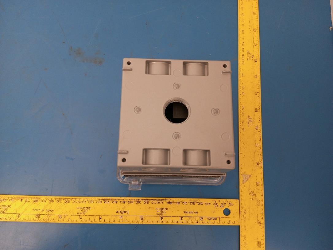
2AFC3-PW24030 amp switch

Grid Connect Inc.
30 amp switch - FCC ID 2AFC3-PW240 - Grid Connect Inc.
Click to zoom

Application Details

Equipment Class
DTS - Digital Transmission System
Date of Grant
Dec 21, 2022
Application Purpose
Original Equipment
Date of Application
Dec 21, 2022
Equipment Note
30 amp switch
Frequency Range
2412.00000000 - 2462.00000000
Company
Grid Connect Inc.
Country
United States

Documents & Files

Select a file to view

Users Manual

↗

Attestation Statements

↗

Cover Letter(s)

↗
↗

External Photos

↗

ID Label/Location Info

↗

Internal Photos

↗

RF Exposure Info

↗

Test Report

↗
↗

Test Setup Photos

↗

Document Text

Text extracted from the exhibit documents filed with the FCC. Open a document above to read the original.

Users Manual

Input Load POWDER WATTS INSTALLATION INSTRUCTIONS PowderWatts.com WARNING: This switch should only be installed by a qualified electrician. This product requires handling of high voltage wiring. Please turn off your circuit breaker and follow instructions carefully. Turn off your circuit breakers and follow safety precautions in order to avoid fire, personal injury, or death. REQUIREMENTS: The PW240 communicates with the Powder Watts Smart Hub and this Hub is required for the smart switching operation of the PW240. WHAT'S IN THE BOX: PW240, Mounting lugs (2), Mounting screws (2), closure plugs (4) WHAT YOU'LL NEED: Phillips head #2 screwdriver, flat head screwdriver, voltmeter, non-contact voltage sensor, and pliers (optional). COMPATIBILITY: PW240 requires a 30 amp circuit with a minimum of 10 gauge wire and can support up to 8 gauge wire. Requires an upstream GFEP circuit breaker. RATING: TURN OFF YOUR BREAKERS: Turn off the circuit breaker. If breakers aren't labeled, turn off the master breaker. Before proceeding - confirm wires are not hot with both a voltmeter and a non-contact voltage sensor. PREPARE INSTALLATION LOCATION: Remove old device (such as a thermostat, timer, or switch, if applicable). Carefully disconnect wires attached to the existing switch or run wire to the installation location. DISASSEMBLE THE PW240: Open the clear cover and set the plastic bag aside. Remove the four screws from the black housing. Gently disconnect the ribbon cable that holds two assemblies together - the gang box (containing the high power electronic board) and top cover (containing the low power electronic board). ATTACH MOUNTING LUGS: Open the plastic bag that was set aside on the previous step. The plastic bag has lugs, screws, and closure plugs. Screw in the contacts to the rear of the closure housing. Gently mount the closure to your preferred location using the lug holes. To avoid damage to the metal or possible stripping, be sure not to over torque these screws. IDENTIFY & STRIP WIRES: You should see 3 types of wires in your wall: Line (Black) • Neutral (White) • Ground (Green or Bare Copper). Be sure your wires have a ½ inch stripped at the end of each wire. If using stranded wire, ensure that all strands are properly fastened to the connector. FEED INPUT CABLES THROUGH BOX: Route the input wire to the input terminals. Attach the supply (input) ground wire to the ground screw. Here is what the connection should look like: Ground INSERT WIRE AND TIGHTEN SCREWS: Insert wires into terminals. Tighten the screws to a proper torque value of 3IN/LB. Tighten the contact screws so that the wire stays in place. Be sure to also connect the ground wire by using the ground screw closest to the input contacts. Use a flathead screwdriver to tighten the terminal screws. INSERT HEAT CABLE WIRES: Insert stripped wire into terminal (recommended 0.32 in. or 8 mm). Use a #2 screwdriver to tighten to 16Ibg-in (1.8Nm). Tighten the contact screws so that the wire stays in place. To make feeding the heat cable wires into the box and controller easier, we recommend temporally twisting them all together, then folding them over back onto themselves fully about 4 inches up - this will result in a hook-like shape that you can then insert, twist and they will pop up though the channel. Please carefully wind all of the strands together using your fingers in a twisting motion. It is important to be sure that no strands of wire are hanging free and not secured by the screw/ lugs. Free strands of wire not secure can lead to shorts and are dangerous. Be sure to also connect the ground wire by using the ground screw closest to the load contacts. Use a proper• screwdriver to tighten the terminal screws. RECONNECT RIBBON CABLE AND REASSEMBLE: Reconnect the ribbon cable and screw the assembly back together using the (4) 2-inch screws that were removed during disassembly. SAFETY CHECK: Double check all wires, look for loose strands, and make sure all screws are tightened. POWER ON SYSTEM: Return to circuit breaker and turn on power. TEST YOUR PW240: Test PW240 by firmly pressing the power button. Green LED indicates the relay has been turned on. INSTALLATION COMPLETE! Download the Powder Watts app and login to your installer account to register the device as part of a Powder Watts Smart Roof system. PW240 SWITCH Cat. No. ANSI/NEMA Config and Electrical Rating PW240 5-30 R 30A, 240V Power Button Relay On/Off - Soft Press Identify - Hold for 10 seconds Power Indicator Reset Button Factory Reset - Hold for 15 seconds Wi-Fi Reset - Hold for 10 seconds Reset Indicator Switch Purple - Default LED Brightness Black - Dimmed LED Brightness RESET LED POWER LED LED State Description LED State Description Yellow - Slow Blink Device ready to add to hub Solid Green Relay State is On Yellow - Fast Blink Connecting to hub Off Relay State if Off Green - Slow Blink Connected to hub Blue - Slow Flash Identify Green - Solid On, then Off Setup complete Red - Fast Blink Failed connection can't connect to hub FCC Statement Red - Slow Blink Setup process failed Blue - Slow Flash Identifies the device TROUBLESHOOTING: To factory reset your PW240, hold the reset button for 15 seconds. For commonly asked questions about the PW240, visit PowderWatts.com/PW240FAQ For patent information, visit powderwatts.com/patent For support, please reach out to [email protected] We are here to help! PowderWatts.com Don't forget to scan the QR code in the Powder Watts app as part of setting up the Powder Watts system before leaving the site of this switch. ISED Statement

Attestation Statements

Real Humans. Expert Support. 1630 W. Diehl Road, Naperville, IL 60563 n Phone: (630) 917-1445 gridconnect.com Attestation Letter FEDERAL COMMUNICATIONS COMMISSIONS Authorization and Evaluation Division 7435 Oakland Mills Road Columbia, MD 21046 Innovation, Science and Economic Development Canada Certification and Engineering Bureau P.O. Box 11490, Station ‘H’ 3701 Carling Ave., Building 94 Ottawa, Ontario K2H 8S2 Canada To Whom Maybe Concern, The RF chip, model: ESP32-WROVER-E, which installed in our product: 30 Amp Switch, model: PW240 (HVIN: GC-PW-IWO-30), FCC ID: 2AFC3-PW240, IC: 22503-PW240, supports 2.4G Wi-Fi and Bluetooth BR/EDR/LE. For use in America and Canada, this chip will only support/enable 2.4G Wi-Fi and Bluetooth LE. Bluetooth BR/EDR function have been disabled by the manufacturer through firmware. Sincerely, Anthony Linder VP Operations

Cover Letter(s)

Authorization Letter Anthony Linder, VP of Operations at Grid Connect is fully authorized to sign FCC & IC submission documents on behalf of Grid Connect. Adam Justice CEO

Cover Letter(s)

Real Humans. Expert Support. 1630 W. Diehl Road, Naperville, IL 60563 n Phone: (630) 917-1445 gridconnect.com FCC Confidential Authorization 2022/09/06 FEDERAL COMMUNICATIONS COMMISSIONS Authorization and Evaluation Division 7435 Oakland Mills Road Columbia, MD 21046 Subject: Confidentiality Request regarding application for certification of FCC ID: 2AFC3-PW240 In accordance with Sections 0.457 and 0.459 of the Commission’s Rules, Grid Connect Inc. hereby requests long-term confidential treatment of information accompanying this application as outlined below: • Block Diagram • Schematics • Operation Description As well as short-term (180 days) confidential treatment of information accompanying this application as outlined below: • Internal Photos • User’s Manual • External Photos • Test Set-up Photos The above materials contain proprietary and confidential information not customarily released to the public. The public disclosure of these materials provides unjustified benefits to its competitors in the market. Sincerely, Anthony Linder, VP Operations [email protected] (630) 245-1445 1630 W. Diehl Rd. Naperville, IL 60563 USA

External Photos

Grid Connect Inc FCC ID: 2AFC3-PW240, IC: 22503-PW240 EUT External Photographs 1.1 EUT Top View 1.2 EUT Bottom View Grid Connect Inc FCC ID: 2AFC3-PW240, IC: 22503-PW240 1.3 EUT Front View 1.4 EUT Left Side View Grid Connect Inc FCC ID: 2AFC3-PW240, IC: 22503-PW240 1.5 EUT Rear View 1.6 EUT Right Side View

ID Label/Location Info

Label and Label Location EUT Bottom View

Internal Photos

Grid Connect Inc FCC ID: 2AFC3-PW240, IC: 22503-PW240 Internal Photographs 1.1 Top-level PCB Top View 1.2 Top-level PCB Bottom View Grid Connect Inc FCC ID: 2AFC3-PW240, IC: 22503-PW240 1.3 Module with Removed Shielding View 1.4 Bottom-level PCB Top View Grid Connect Inc FCC ID: 2AFC3-PW240, IC: 22503-PW240 1.5 Bottom-level PCB Bottom View 1.6 Antenna View

RF Exposure Info

Grid Connect Inc. FCC ID: 2AFC3-PW240, IC: 22503-PW240 Report Number: R2208033-DTS Page 17 of 98 FCC Part 15C/ISEDC RSS-247 Report FCC §15.247(i) §2.1091 & ISED RSS-102 - RF Exposure Applicable Standards According to FCC KDB 447498 D04 Interim General RF Exposure Guidance v01, Section 2.1 RF Exposure Test Exemptions for Single Source, 2.1.1 General RF Exposure Test Exemption Considerations RF exposure test exemptions provide means to obtain certification without the need of showing data (measurements, or analytical/numerical modeling) to demonstrate compliance. Hereafter, in this context, an RF source is referred to as “exempt RF device” in the sense that it is not required to show data demonstrating compliance to RF exposure limits. Test exemptions apply for devices used in general population/uncontrolled exposure environments, according to the SAR-based, or MPE-based exemption thresholds. 8 However, it is always possible, especially when the potential for exposure cannot be easily determined, that an RF exposure evaluation may become required according §§ 1.1307(c) and (d). As detailed in Section 2.1.2, the 1 mW and SAR-based test exemption conditions are in terms of source-based available maximum time-averaged (matched conducted) output power for all operating configurations, adjusted for tune-up tolerance, and at the minimum test separation distance required for the particular RF exposure scenario under consideration. This minimum test separation distance is determined by the smallest distance from the antenna and radiating structures or outer surface of the device, according to the host form factor, exposure conditions and platform requirements, to any part of the body or extremity of a user or bystander. To qualify for SAR test exemption, the test separation distances applied must be fully explained and justified (typically in the SAR measurement, or SAR analysis report, according to KDB Pub. 865664) by showing the actual operating configurations and exposure conditions of the transmitter, and applicable host platform requirements (e.g., KDB Pubs. 648474, 616217, 941225) When no other RF exposure testing or reporting is required, a statement of justification and compliance must be included in the equipment approval, in lieu of the SAR report, to qualify for SAR test exemption. If RF exposure testing requirements for a specific device are covered in a KDB Publication, those requirements must be satisfied before applying any SAR test exemption provisions. For example, this is the case for handheld PTT two-way radios, handsets, laptops, and tablets, etc. 9 Finally, when 10-g extremity SAR applies, SAR test exemption may be considered by applying a factor of 2.5 to the SAR-based exemption thresholds. 2.1.2 1-mW Test Exemption Per §1.1307(b)(3)(i)(A), a single RF source is exempt RF device (from the requirement to show data demonstrating compliance to RF exposure limits, as previously mentioned) if the available maximum time- averaged power is no more than 1 mW, regardless of separation distance. This exemption applies to all operating configurations and exposure conditions, for the frequency range 100 kHz to 100 GHz, regardless of fixed, mobile, or portable device exposure conditions. This is a standalone exemption, and it cannot be applied in conjunction with any other test exemption. 2.1.3 SAR-Based Exemption Grid Connect Inc. FCC ID: 2AFC3-PW240, IC: 22503-PW240 Report Number: R2208033-DTS Page 18 of 98 FCC Part 15C/ISEDC RSS-247 Report A more comprehensive exemption, considering a variable power threshold that depends on both the separation distance and power, is provided in §1.1307(b)(3)(ii)(B). This exemption is applicable to the frequency range between 300 MHz and 6 GHz, with test separation distances between 0.5 cm and 40 cm, and for all RF sources in fixed, mobile, and portable device exposure conditions. Accordingly, a RF source is considered an RF exempt device if its available maximum time-averaged (matched conducted) power or its effective radiated power (ERP), whichever is greater, are below a specified threshold. This exemption threshold was derived based on general population 1-g SAR requirements and is detailed in Appendix C. 2.1.4 MPE-Based Exemption An alternative to the SAR-based exemption is provided in §1.1307(b)(3)(ii)(C), for a much wider frequency range, from 300 kHz to 100 GHz, applicable for separation distances greater or equal to λ/2π, where λ is the free-space operating wavelength in meters. The MPE-based test exemption condition is in terms of ERP, defined as the 8 Specific test exemption thresholds for operations under occupational/controlled limits are not established. 9 When SAR evaluation is required by the hotspot mode or UMPC mini-tablet procedures, that is, where an antenna is ≤ 2.5 cm from a surface or edge, the test separation distance from the phantom to the antenna or device enclosure, as appropriate, should be applied to determine SAR test exemption for such configurations, according to the criteria in this document. For that case, the test separation distance cannot be determined from the distance of the antenna to the device surface or edge. According to ISED RSS-102 Issue 5 Section 2.5.1 Exemption Limits for Routine Evaluation-SAR Evaluation: SAR evaluation is required if the separation distance between the user and/or bystander and the antenna and/or radiating element of the device is less than or equal to 20 cm, except when the device operates at or below the applicable output power level (adjusted for tune-up tolerance) for the specified separation distance defined in table below, Frequency (MHz) Exemption Limits (mW) At separation distance of ≤5 mm At separation distance of 10 mm At separation distance of 15 mm At separation distance of 20 mm At separation distance of 25 mm ≤300 71 101 132 162 193 450 52 70 88 106 123 835 17 30 42 55 67 1900 7 10 18 34 60 2450 4 7 15 30 52 3500 2 6 16 32 55 5800 1 6 15 27 41 Grid Connect Inc. FCC ID: 2A…

Text truncated - open the document above for the full version.

Test Report

Note: This test report was prepared for the customer shown above and for the device described herein. It may not be duplicated or used in part without prior written consent from Bay Area Compliance Laboratories Corp. This test report shall not be used by the customer to claim product certification, approval, or endorsement by A2LA or any agency of the United States Government or any foreign government. * This test report may contain data and test methods that are not covered by BACL’s scope of accreditation as of the test report date shown above. These items are marked within the test report text with an asterisk “*” \ FCC PART 15, SUBPART C ISEDC RSS-247, ISSUE 2, FEBRUARY 2017 TEST REPORT For Grid Connect Inc. 1630 W Diehl Rd, Naperville, IL, 60563 FCC ID: 2AFC3-PW240 IC: 22503-PW240 R e p o r t T y p e : O r i gi n a l R e p o r t P r o d u c t T y p e : 3 0 A m p S w i t c h Prepared By: Tao Jin Test Engineer Report Number: R2208033-DTS Report Date: 2022-10-12 Reviewed By: Christian McCaig RF Lead Engineer Bay Area Compliance Laboratories Corp. 1274 Anvilwood Avenue, Sunnyvale, CA 94089, USA Tel: (408) 732-9162 Fax: (408) 732-9164 Grid Connect Inc. FCC ID: 2AFC3-PW240, IC: 22503-PW240 Report Number: R2208033-DTS Page 2 of 98 FCC Part 15C/ISEDC RSS-247 Report TABLE OF CONTENTS General Description ..................................................................................................................................................... 5 Product Description for Equipment Under Test (EUT) ...................................................................................... 5 Mechanical Description ...................................................................................................................................... 5 Objective ............................................................................................................................................................. 5 Related Submittal(s)/Grant(s) ............................................................................................................................. 5 Test Methodology ............................................................................................................................................... 6 Measurement Uncertainty ................................................................................................................................... 6 Test Facility Registrations .................................................................................................................................. 6 Test Facility Accreditations ................................................................................................................................ 7 System Test Configuration.......................................................................................................................................... 9 Justification ......................................................................................................................................................... 9 EUT Exercise Software..................................................................................................................................... 10 Duty Cycle Correction Factor ........................................................................................................................... 11 Equipment Modifications.................................................................................................................................. 14 Local Support Equipment ................................................................................................................................. 14 Remote Support Equipment .............................................................................................................................. 14 Interface Ports and Cabling ............................................................................................................................... 14 Summary of Test Results ............................................................................................................................................ 15 FCC §15.203 & ISEDC RSS-Gen §6.8 - Antenna Requirements ............................................................................ 16 Applicable Standards ........................................................................................................................................ 16 Antenna Description ......................................................................................................................................... 16 FCC §15.247(i) §2.1091 & ISED RSS-102 - RF Exposure ....................................................................................... 17 Applicable Standards ........................................................................................................................................ 17 FCC RF Exposure Exemption Evaluation Procedures ...................................................................................... 19 RF exposure evaluation exemption for FCC ..................................................................................................... 23 RF exposure evaluation exemption for IC ........................................................................................................ 23 FCC §15.207 & ISEDC RSS-Gen §8.8 - AC Line Conducted Emissions ................................................................ 24 Applicable Standards ........................................................................................................................................ 24 Test Setup ......................................................................................................................................................... 24 Test Procedure ..............................................................................................................................................…

Text truncated - open the document above for the full version.

Test Report

Confidential Inventek Systems, LLC. DOC-DS-20075-1.0 Page 1 of 8 Inventek Systems OEM Wi-Fi Antennas P/N: W24P-U Confidential Inventek Systems, LLC. DOC-DS-20075-1.0 Page 2 of 8 Table of Contents 1 GENERAL DESCRIPTION ....................................................................................... 3 2 PART NUMBER DETAIL DESCRIPTION .............................................................. 3 Ordering Information................................................................................................. 3 3 GENERAL FEATURES ............................................................................................. 3 3.1 Environmental Specifications ............................................................................. 3 4 Features ....................................................................................................................... 4 5 Applications ................................................................................................................ 4 6 Electrical Specifications.............................................................................................. 4 6.1 Return Loss(S¹¹) .................................................................................................. 4 6.2 Smith Chart(S¹¹) .................................................................................................. 5 7 Antenna Dimensions (unit: mm) ................................................................................. 5 8 Radiation Pattern ......................................................................................................... 6 8.1 3D Gain Pattern (Radiation Pattern at 2442 MHz) ............................................. 6 8.2 9-2 Efficiency Table ........................................................................................... 7 8.3 9-3 Efficiency vs. Frequency .............................................................................. 7 9 Electrical Specifications.............................................................................................. 7 10 REVISION CONTROL .............................................................................................. 8 11 CONTACT INFORMATION ..................................................................................... 8 Confidential Inventek Systems, LLC. DOC-DS-20075-1.0 Page 3 of 8 1 GENERAL DESCRIPTION The Inventek 2400-2500 Mhz Wi-Fi PCB (30 x 5 mm) antennas let you integrate Wi-Fi functionality into your product quickly and easily. It’s suitable for a wide range of applications and recommended for use with Inventek eS-Wi-Fi modules. 2 PART NUMBER DETAIL DESCRIPTION Ordering Information Device Description Ordering Number W24P-U 2400-2500 Mhz Wi-Fi PCB antenna with U.Fl connector and 90 mm cable length W24P-U 3 GENERAL FEATURES Characteristics Specifications Unit Outline Dimensions 30 x 5.0 x .05 mm Center Frequency 2442 MHz Bandwith 100 min. MHz VSWR 2 max. Impedance 50 Ω Polarization Linear Polarization Gain Peak 3.2 (typical) dBi Efficiency 79 (typical) % 3.1 Environmental Specifications Item Description Operating temperature rang -40 deg. C to +80 deg. C Storage temperature range -55 deg. C to +100 deg. C Humidity 95% max non-condensing Confidential Inventek Systems, LLC. DOC-DS-20075-1.0 Page 4 of 8 4 Features  Stable and reliable in performances  PCB antenna has excellent sensitivity to consistently provide high signal reception efficiency  Compact size  RoHS compliance 5 Applications *IEEE802.11 (b/g/n). *Hand-held devices when WiFi (802.11 b/g/n) functions are needed. 6 Electrical Specifications 6.1 Return Loss(S¹¹) Confidential Inventek Systems, LLC. DOC-DS-20075-1.0 Page 5 of 8 6.2 Smith Chart(S¹¹) 7 Antenna Dimensions (unit: mm) Our standard cable length is 90mm long. Minimum order custom cable lengths can be special order by request. Confidential Inventek Systems, LLC. DOC-DS-20075-1.0 Page 6 of 8 8 Radiation Pattern 8.1 3D Gain Pattern (Radiation Pattern at 2442 MHz) 2.4 Confidential Inventek Systems, LLC. DOC-DS-20075-1.0 Page 7 of 8 8.2 9-2 Efficiency Table 8.3 9-3 Efficiency vs. Frequency 9 Electrical Specifications Frequency(GHz) 2.400 2.412 2.417 2.422 2.427 2.432 2.437 2.442 2.447 2.452 2.457 2.462 2.467 2.472 2.484 Efficiency(dB) -1.51 -1.26 -1.21 -1.13 -1.09 -0.99 -0.90 -1.01 -1.06 -1.04 -0.87 -0.79 -0.82 -0.86 -0.98 Efficiency (%) 70.63 74.82 75.68 77.09 77.80 79.62 81.28 79.25 78.34 78.70 81.85 83.37 82.79 82.04 79.80 Gain(dBi) 2.76 2.96 3.02 3.05 3.15 3.24 3.32 3.26 3.23 3.26 3.42 3.55 3.56 3.58 3.48 Confidential Inventek Systems, LLC. DOC-DS-20075-1.0 Page 8 of 8 RoHS: Restriction of Hazardous Substances (RoHS) directive has come into force since 1st July 2006 all electronic products sold in the EU must be free of hazardous materials, such as lead. 10 REVISION CONTROL Document : W24P-U 2.4 Ghz PCB antenna Internal Release DOC-DS-20075 Date Author Revision Comment 10/1/2013 FMT 1.0 Preliminary 11 CONTACT INFORMATION Inventek Systems 2 Republic Road Billerica Ma, 01862 Tel: 978-667-1962 [email protected] www.inventeksys.com Inventek Systems reserves the right to make changes without further notice to any products or data herein to improve reliability, function, or design. The information contained within is believed to be accurate and reliable. However Inventek Systems does not assume any liability arising out of the application or use of this information, nor the application or use of any product or circuit described herein, neither does it convey any license under its patent rights nor the rights of others.

Test Setup Photos

Grid Connect Inc FCC ID: 2AFC3-PW240, IC: 22503-PW240 EUT Test Setup Photographs 1.1 30 MHz – 1 GHz at 3 Meters Front View 1.2 30 MHz – 1 GHz at 3 Meters Rear View Grid Connect Inc FCC ID: 2AFC3-PW240, IC: 22503-PW240 1.3 1 – 18 GHz at 1 Meter Front View 1.4 1 – 18 GHz at 1 Meter Rear View Grid Connect Inc FCC ID: 2AFC3-PW240, IC: 22503-PW240 1.5 1 – 18 GHz at 3 Meter Front View 1.6 1 – 18 GHz at 3 Meter Rear View Grid Connect Inc FCC ID: 2AFC3-PW240, IC: 22503-PW240 1.7 18 – 26.5 GHz at 1 Meter Front View 1.8 18 – 26.5 GHz at 1 Meter Rear View Grid Connect Inc FCC ID: 2AFC3-PW240, IC: 22503-PW240 1.9 AC Power-Line Setup Front View 1.10 AC Power-Line Setup Side View

Contact Information

Applicant

Adam Justice(VP)
[email protected]6302451445Fax: 6302451717

Test Firm

Bay Area Compliance Laboratories Corp.Lisa Tang
[email protected]408-732-9162Fax: 408 732 9164

Technical Specifications

#Rule PartsFrequency RangePower Output
215C2.41 GHz - 2.46 GHz51.00 mW
Confidentiality
Long Term
Grant Notes
Output power listed is conducted. The antenna(s) used for this transmitter must be installed to provide a separation distance of at least 20 cm from all persons and must not be co-located or operating in conjunction with any other antenna or transmitter. Users and installers must be provided with antenna installation instructions and transmitter operating conditions for satisfying RF exposure compliance. The device supports 20 MHz and 40 MHz bandwidth modes.

Other Applications from Grid Connect Inc.

Smart Outlet - FCC ID 2AFC3GCCSSO - Grid Connect Inc.
2AFC3GCCSSO

Smart Outlet

Aug 29, 2015

Equipment Class

DTS - Digital Transmission System